说明书.doc

汽车零件加工自动线上的多功能机械手的设计【优秀毕业设计】【word+4张CAD图纸全套】

收藏

压缩包内文档预览:(预览前20页/共32页)
预览图 预览图 预览图 预览图 预览图 预览图 预览图 预览图 预览图 预览图 预览图 预览图 预览图 预览图 预览图 预览图 预览图 预览图 预览图 预览图
编号:295457    类型:共享资源    大小:2.54MB    格式:RAR    上传时间:2014-07-08 上传人:QQ14****9609 IP属地:陕西
50
积分
关 键 词:
汽车零件 加工 自动 线上 多功能机械手 设计 优秀 优良 毕业设计 word cad 图纸 全套
资源描述:

汽车零件加工自动线上的多功能机械手的设计【优秀毕业设计】【word+4张CAD图纸全套】

【带任务书+开题报告+答辩资格审查表+答辩及最终成绩评定表+工作中期检查表+指导教师评阅表+实习日记+外文翻译】【30页@正文11300字】【详情如下】【全套设计需要咨询请加QQ1459919609】

任务书.doc

外文文献 2.doc

外文文献原文.pdf

工作进度检查表.doc

开题报告.doc

手臂和腕部结构A0.dwg

手部结构图A1.dwg

指导教师评阅表.doc

液压系统原理图.A1dwg1.dwg

答辩及最终成绩评定表.doc

答辩资格审查表.doc

表格.doc

装配图A0.dwg

评阅教师评阅表.doc

说明书.doc

任务书

课题名称汽车零件加工自动线上的多功能机械手的设计

内容及任务

本课题为汽车零件加工自动线的辅助装置之一,机械手在零件加工自动线上完成上料、转位和翻转等多种功能。

2、设计内容

(1)机械手的总装图,

(2)部件装配图及零件图,

(3)机械手液压系统工作原理图;

(4)设计计算说明书:1份

(所有图纸折合不得少于3张A0图)

拟达到的要求或技术指标1、设计(论文)基本要求

(1)材料牌号,形位公差,粗糙度,图纸的标题栏及明细表都宜采用新图标。

(2)设计应以独立完成为主,图纸表达要正确清晰,计算正确,能借助各种工具书和技术资料获得所需的正确数据。

(3)说明书应内容完整,字迹工整,语言简练,文字通顺。说明书中应重点包括设计方案的分析与论证,考虑问题的出发点和最后选择的依据,必要的计算过程,其他说明等

2、主要技术指标:

(1)最大抓取重量:15Kg;

(2)工件最大尺寸(长×宽×高)250×170×140mm

(3)最大操作范围:提升高度1.5m;回转半径1m;行走范围≤30m;

(4)机械手的自由度:4~5个;

(5)定位精度:0.5~1mm;

(6)装料高度:1050mm;输送轨道宽度:350mm;输送速度:20m/min

(7)生产纲领:10万件/年;生产节拍:3min/件;

(8)性能要求:抓取灵活,送放平稳,安全可靠,寿命不低于15年。

进度安排起止日期工作内容备注

第2~5周毕业调研及实习、搜集设计的相关资料,写出开题报告

第6~8周设计方案的确定

第9~11周完成部件装配图及零件图的绘制

第12~15周编写设计计算说明书, 通过指导老师验收,准备答辩

第16周毕业答辩

主要参考资料[1] 刘心治主编.冷冲压工艺及模具设计[M].重庆:重庆大学出版社,2006.5~10

[2] 模具制造手册 编写组.模具制造手册[J].北京:机械工业出版社,1990.2

[3] 工程材料及机械制造基础 系列教材编写委员会.机械工程材料基础[M].湖南:中南大学出版社,1995,13~47

[4] 刘守勇主编.机械制造工艺与机床夹具[M].北京:机械工业出版社,1995.55~56

[5] 章跃主编.机械制造工程专业英语[M].北京:机械工业出版社,2005.77~78

[6] 甘永立主编.几何量公差与检测[M].上海:科学技术出版社,2005.12~13

[7] 吴宗泽主编.机械设计手册[J](上册 下册).北京:机械工业出版社,1998.99~105

[8] 杨恢先,黄辉先等编著.单片机原理及应用[M].长沙:国防科技大学出版社,2003

[9] 何永然,唐增宝,刘安俊主编.机械设计课程设计(第二版)[M].武汉:

华中科技大学出版社,2002. 58~88

[10] 周良德,朱泗芳等编著.现在工程图学[M].长沙:湖南科学技术出版社,2000

[11] 华中理工大学等院校编,画法几何及机械制图[M].北京:高等教育出版社,2003

[12] 冯炳尧,韩泰荣,殷振海,蒋文森编.模具设计与制造简明手册[J].上海:

上海科学技术出版社,1992. 108~120

[13] 冲模设计手册 编写组.冲模设计手册[J].北京:机械工业出版社,1988.14~15

[14] 王卫卫主编.材料成形设备[M].北京:机械工业出版社,2004.49~50

摘  要

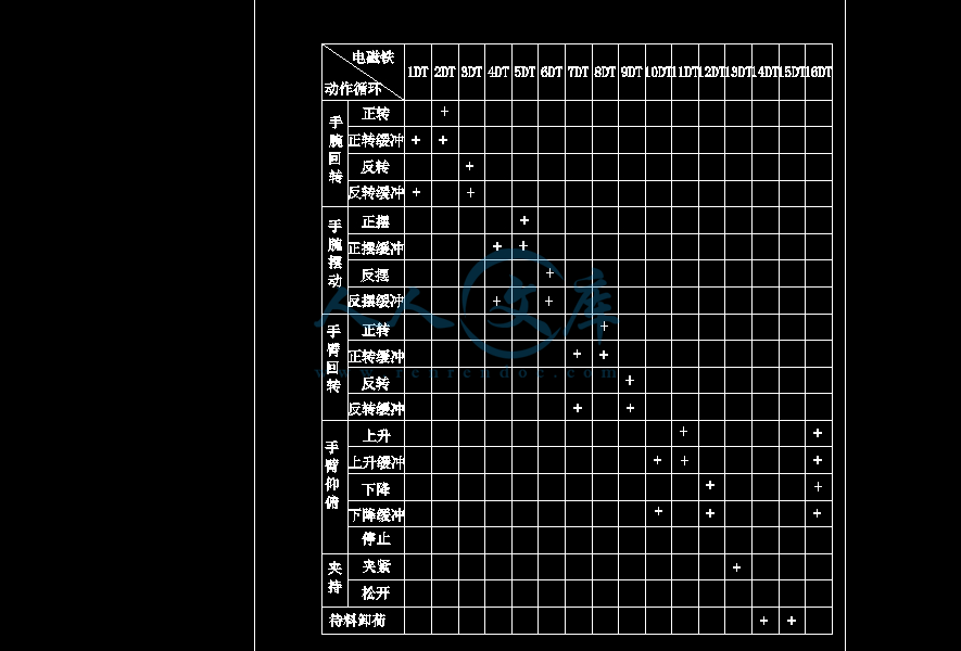
本次设计的多功能机械手用于汽车零件加工自动线上的设计,主要由手爪、手腕、手臂、机身、机座等组成,具备上料、翻转和转位等多种功能,并按该自动线的统一生产节拍和生产纲领完成以上动作。本机械手机身采用机座式,自动线围绕机座布置,其坐标形式为球坐标式,具有立柱旋转、手臂伸缩、手臂俯仰、腕部转动和腕部摆动4个自由度。驱动方式为液压驱动,选用双泵,共有整机回转油缸、手臂俯仰油缸、手臂伸缩油缸、手腕摆动油缸、手腕回转油缸、手爪夹紧油缸6个液压缸。送放机构的液压驱动系统是由液压基本回路组成,包括调压回路,缓冲回路,调速回路,换向回路.锁紧回路,保压回路。定位采用机械挡块定位,定位精度为0.5~1mm,采用行程控制系统实现点位控制。

关键词:  机械手,自动线,液压,设计 ,点位控制

ABSTRACT

The current design of multifunctional mechanical hand used for R175-type diesel organisms automatic processing line, mainly consist of claw, wrists, arms, body, base and so on. With moving the materials, turnover and transfer spaces, and many other functions, the automatic line with the unified production rhythms and production program completed more moves. With the automatic production line rhythms and the production of complete reunification of the above movements, automatic line is around the machine arrange, the coordinates of the ball coordinates of the form, with huge rotary, extendable arm, arm pitch, hitting and hitting back five moves freedom; Driven approach to hydraulic-driven, and the choice of double leaves pumps, the system pressure to 2.5MPa, 5.5KW electrical power for a total of whole sets of rotation tank, arm tilt cylinders, fuel tanks extendable arm, wrist swing tank, wrist rotation tank, claw clip tank six hydraulic oil tank; positioning a piece of machinery turned positioning, positioning accuracy for 0.5~1mm, using control systems to achieve their point spaces control.

Key words: Mechanical hand, the ball coordinates, hydraulic, mechanical turned pieces, control point spaces

目  录

1绪论1

1.1机械手的概述1

1.2机械手的组成与分类1

1.2.1机械手的组成1

1.3机械手的分类2

1.3 机械手的组成3

2总体方案分析4

2.1总体方案分析4

2.2方案的确定4

2.3动作原理4

2.4 主要技术指标5

3手部的设计6

3.1手部结构6

3.2手爪的计算与分析6

3.2.1手爪执行液压缸工作压力计算6

3.2.2  手爪的夹持误差分析与计算7

4腕部的设计8

4.1腕部结构8

4.2 腕部回转力矩的计算8

5手臂的设计11

5.1手臂伸缩液压缸的设计计算11

5.1.1手臂作水平伸缩直线运动驱动力的计算11

5.1.2手臂垂直升降运动驱动力的计算11

5.1.3确定液压缸的结构尺寸12

5.1.4液压缸壁厚计算12

5.1.5活塞杆的计算13

5.1.6液压缸端盖的联接方式与强度计算13

5.1.6缸盖螺钉计算13

5.1.7缸体螺纹计算14

5.2手臂俯仰运动的设计计算15

5.2.1手臂俯仰时所需的驱动力矩15

5.2.2缸盖联接螺钉计算和动片联接螺钉计算16

5.2.3动片联接螺钉的计算16

6.机身设计18

6.1机身结构的计算18

6.2机身设计时应注意的事项19

7机械手液压系统的工作原理20

7.1液压系统的组成20

7.2液压传动系统机械手的特点20

7.3油缸泄漏问题与密封装置20

7.3.1活塞式油缸的泄漏与密封21

7.3.2回转油缸的泄漏与密封21

7.4液压系统传动方案的确定22

7.4.1各液压缸的换向回路22

7.4.2调整方案22

7.4.3减速缓冲回路22

7.4.4系统安全可靠性23

参考文献25

致  谢26

1绪论

1.1机械手的概述

工业机械手(以下简称机械手)是近代自动控制领域中出现的一项新技术,作为多学科融合的边沿学科,它是当今高技能发展速度最快的领域之一,并已经成为现代机械制造生产系统中的一个重要组成部分。

所谓工业枢机手就是一种能按给定的程序或要求自动完成物件(如材料、工件、零件或工具等)传送或操作作业的机械装置,它能部分地代替人的手工劳作。较高级型式的机械手,还能模拟人的手臂动作,完成较复杂的作业。

1.2机械手的组成与分类

1.2.1机械手的组成

工业机械手是由执行机构、驱动系统和控制系统所组成,各部关系如图1所示:

                   图1  工业机械手组成图框

机械手大致可分为手部、传送机构、驱动部分、控制部分以及其他部分。

手部(或称抓取机构)包括手指、传力机构等.主要起抓取和放置物件的作用;

传送机构(或称臂部)包括手腕、手臂等.主要起改变物件方向和位置的作用;

驱动部分 它是驱动前两部分的动力.因此也称动力源,常用的有液压、气压、电力和机械式驱动等四种形式;

控制部分 它是机械手动作的指挥系统.它来控制动作的顺序(程序)、位置和时间(甚至速度与加速度)等;

其它部分 如机体、行走机构、行程检测装置和传感装置等。

1.3机械手的分类

机械手从使用范围、运动坐标形式、驱动方式以及臂力大小四个方面的分类分别为:

(1)按机械手的使用范围分类:

   1)专用机械手

一般只有固定的程序,而无单独的控制系统。它从属于某种机器或生产线用以自动传送物件或操作某一工具,例如“毛胚上下料机械手”、“曲拐自动车床机械手”、“油泵凸轮轴自动线机械手”等等。这种机械手结构较简单,成本较低,适用于动作比较简单的大批量生产的场合。

 2) 通用机械手(也称工业机器人)

指具有可变程序和单独驱动的控制系统,不从属于某种机器,而且能自动生成传送物件或操作某些工具的机械装置。通用机械手按其定位和控制方式的不同,可以分为简易型和伺服型两种。简易型只是点位控制,故属于程序控制类型,伺服型可以是点位控制,也可以是连续轨迹控制,一般属于数字控制类型。这种机械手由于手指可以更换(或可调节),程序可变,故适用于中、小批生产。但因其运动较多,结构复杂,技术条件要求较高,故制造成本一般也较高。

按机械手臂部的运动坐标型式分类:

1)直角坐标式机械手

臂部可以沿直角坐标系X、Y、Z三个方向移动,亦即臂部可以前后伸缩(定为沿X方向移动)、左右移动(定为沿Y方向移动)和上下升降(定为沿Z方向的移动);

参考文献

[1]李允文.工业机械手设计[M].北京.机械工业出版社,1994.

[2]徐灏.机械设计手册第五卷[M].北京.机械工业出版社,1992.

[3]沈鸿.机械设计手册第十卷[M].北京.机械出版社,1982.

[4]孟宪源.现代机构手册下册[M].北京.机械工业出版社,1994.

[5]吴振彪.工业机器人.武汉[M].华中科技大学出版社,2000.

[6]左健民.液压与气压传动[M].武汉华中科技大学出版社,1992.

[7]陈启松.液压传动与控制手册[M].上海.上海科技大学出版社,2006.

[8]刘军营.液压与气压传动.西安[M].西安电子科技大学出版社,2007.

[9]吴卫荣.液压技术[M].北京中国轻工业出版社,2006

[10]张世亮.液压与气压传动[M].北京.机械工业出版社,2006.

[11]雷天觉.液压工程手册[M].北京.机械工业出版社,1990.

[12]廖常初.可编程序控制器的编程方法与工程应用[M].重庆大学出,2000.

[13]王守城、段俊勇.液压元件及选用[M].北京.化学工业出版社,2007

[14]黄继昌,徐巧鱼.现代机构图册[M].北京.机械工业出版社,2008

[15]李天元.简明机械工程手册[M].云南.云南科技出版社,1998.

[16]何国金.机械电气自动控制[M].重庆.重庆大学出版社,2002.

[17]谢忠安.自动控制系统[M].重庆.重庆大学出版社,2003.

[18]纪名刚.机械设计[M].北京.高等教育出版社,2000.

[19]袁子荣.液压与气压控制技术基础[M].重庆.重庆大学出版社,2005

[20]唐仲文.机电一体化技术应用实例[M].北京.机械工业出版社,1994.

内容简介:
任务书院(系):机械工程学院 专业:机械设计制造及其自动化指导教师刘吉兆学生姓名刘世平课题名称汽车零件加工自动线上的多功能机械手的设计内容及任务本课题为汽车零件加工自动线的辅助装置之一,机械手在零件加工自动线上完成上料、转位和翻转等多种功能。2、设计内容(1)机械手的总装图,(2)部件装配图及零件图, (3)机械手液压系统工作原理图;(4)设计计算说明书:份(所有图纸折合不得少于3张A0图)拟达到的要求或技术指标1、设计(论文)基本要求(1)材料牌号,形位公差,粗糙度,图纸的标题栏及明细表都宜采用新图标。(2)设计应以独立完成为主,图纸表达要正确清晰,计算正确,能借助各种工具书和技术资料获得所需的正确数据。(3)说明书应内容完整,字迹工整,语言简练,文字通顺。说明书中应重点包括设计方案的分析与论证,考虑问题的出发点和最后选择的依据,必要的计算过程,其他说明等2、主要技术指标:(1)最大抓取重量:15Kg;(2)工件最大尺寸(长宽高)250170140mm(3)最大操作范围:提升高度1.5m;回转半径1m;行走范围30m;(4)机械手的自由度:45个;(5)定位精度:0.51mm;(6)装料高度:1050mm;输送轨道宽度:350mm;输送速度:20m/min(7)生产纲领:10万件/年;生产节拍:3min/件;(8)性能要求:抓取灵活,送放平稳,安全可靠,寿命不低于15年。进度安排起止日期工作内容备注第25周毕业调研及实习、搜集设计的相关资料,写出开题报告第68周设计方案的确定第911周完成部件装配图及零件图的绘制第1215周编写设计计算说明书, 通过指导老师验收,准备答辩第16周毕业答辩主要参考资料1 刘心治主编.冷冲压工艺及模具设计M.重庆:重庆大学出版社,2006.5102 模具制造手册 编写组.模具制造手册J.北京:机械工业出版社,1990.23 工程材料及机械制造基础 系列教材编写委员会.机械工程材料基础M.湖南:中南大学出版社,1995,13474 刘守勇主编.机械制造工艺与机床夹具M.北京:机械工业出版社,1995.55565 章跃主编.机械制造工程专业英语M.北京:机械工业出版社,2005.77786 甘永立主编.几何量公差与检测M.上海:科学技术出版社,2005.12137 吴宗泽主编.机械设计手册J(上册 下册).北京:机械工业出版社,1998.991058 杨恢先,黄辉先等编著.单片机原理及应用M.长沙:国防科技大学出版社,20039 何永然,唐增宝,刘安俊主编.机械设计课程设计(第二版)M.武汉:华中科技大学出版社,2002. 588810 周良德,朱泗芳等编著.现在工程图学M.长沙:湖南科学技术出版社,200011 华中理工大学等院校编,画法几何及机械制图M.北京:高等教育出版社,200312 冯炳尧,韩泰荣,殷振海,蒋文森编.模具设计与制造简明手册J.上海:上海科学技术出版社,1992. 10812013 冲模设计手册 编写组.冲模设计手册J.北京:机械工业出版社,1988.141514 王卫卫主编.材料成形设备M.北京:机械工业出版社,2004.4950教研室意见年 月 日主管领导意见年 月 日 外文翻译Design and Development of a Competitive Low-Cost Robot Arm with Four Degrees of Freedom一个具有竞争力的低成本的四自由度机械人手臂的设计与开发 院 、 部: 机械工程学院 专业名称:机械设计制造及其自动化 学生姓名: 刘世平 学 号: 10201420716 指导老师: 刘吉兆 职称: 教授 完成日期 2014年 5月摘 要这项工作的主要重点是设计,开发和实施具有竞争力的机器人手臂具有增强控制和粗短的成本。机器人手臂的设计采用四自由度和才华来完成精确简单的任务,如光材料处理,这将被整合到了作为一个助理为工业劳动力的移动平台。机器人手臂上配有数个伺服电机的臂之间做链接和执行的手臂动作。伺服电机编码器包括使没有控制器实施。控制我们使用LabVIEW ,它执行逆运动学计算和串行通信的适当的角度,以一个微控制器,驱动伺服电机,修改的位置,速度和加速度的能力的机器人。机器人手臂的测试和验证,进行和结果表明,正常工作。关键词:机器人手臂,低成本,设计,验证,四自由度,伺服电机, Arduino的的机器人控制, Labview的机器人控制目 录1引言12机械设计13机械手逆运动64最终选择效应65机械手的控制75.1逆运动学控制85.2 手动96测试和验证107结果与讨论117.1伺服电机运动范围117.2 电流消耗127.3 最大负载127.4 最终位置128 结论13参考文献141引言机器人实际上是定义为研究,设计和使用机器人系统的制造1。机器人通常用于执行不安全的,危险的,高度重复的,和单调的任务。它们具有许多不同的功能,如材料处理,组装,电弧焊接,电阻焊接,机床的装载和卸载功能,刷涂,喷涂等。主要有两种不同类型的机器人:一个服务机器人以及工业机器人。服务机器人是机器人,工作半或完全自主地去履行服务,有用的福祉人类和设备,但不包括生产操作2 。工业用机器人,在另一方面,被正式通过ISO定义的自动控制和多用途可编程操纵器在三个或更多个轴3。工业机器人是移动的材料,零件,工具,或通过可变的程式动作的专门设备来执行各种任务。工业机器人系统不仅包括工业机器人,但也能够执行其任务以及测序或监视通信接口需要对机器人的任何设备和/或传感器。2007年全球市场增长了3,约114,000新安装的工业机器人。截至2007年底,全国共有大约一万个工业机器人的使用,估计有50,000服务机器人用于工业用途比较3 。由于增加使用工业机器人手臂,演变到该主题开始试图模仿人类动作的细节模式。例如一组学生在韩国做创新的设计,为舞蹈的手,举重,中国书法和颜色分类机械臂考虑4 。另一组工程师在美国开发八个自由度机械臂。该机器人是能够把握多个对象与很多从笔形状的一球,也模拟人类的手5。在空间上,航天飞机遥控器系统,被称为SSRMS或Canadarm ,其继任者是例子多度已经用来执行各种使用专门部署热潮的任务,例如航天飞机的检查自由机械臂有摄像头和连接在末端执行器和卫星的部署和检索演习从货舱航天飞机传感器6 。在墨西哥,科学家们已经上了轨道设计和发展许多机器人的手臂,墨西哥政府估计,在墨西哥有在不同的工业应用中使用了大约11,000机械臂。不过,专家认为,机器人手臂的最高点,不仅质量更高,而且准确,可重复性和粗短的成本。 大多数机器人都设置了一个操作的示教和重复技术。在这种模式下,一个训练有素的操作者(编程器)通常使用的便携式控制装置(示教)手动教机器人的任务。在这些编程会话机器人的速度很慢。 目前的工作是一个两阶段的项目,这需要一个移动机器人能够运送工具从存储室到工业单元的一部分。在这个阶段中的项目,该项目开展了在科技,墨西哥蒙特雷大学,主要的重点是设计, 制定和实施了工业机器人手臂粗短的成本,准确和优越的控制。这个机器人手臂的设计采用四自由度和才华来完成简单的任务,如光队友里亚尔处理,这将被整合到移动平台的形式,作为一个助理为工业劳动力。2机械设计 机器人手臂的机械设计是基于一个机器人操作器具有类似功能的一个人的手臂6-8。这样的操纵器的链接是由关节,允许旋转运动和操纵器的链接被认为形成一个运动链连接。机械手的运动链的业务最终被称为末端效应器或臂端的 - 工具,它是类似于人的手。图1显示了自由体图的机器人手臂的机械设计。图1 机械手的自由体图 如图所示,端部执行器不包括在设计,因为市售的夹持器被使用。这是因为端部执行器是系统中最复杂的部分之一,并且,反过来,这是很容易和经济地使用商业化生产它。 图2示出了机器人手臂的工作区域。图2 机械手工作区域图这是一个机器人臂具有四个自由度(DOF 4)的典型的工作空间。机械设计仅限于4自由度,主要是因为,这样的设计允许大部分必要的运动,并保持 成本和机器人竞争的复杂性。因此,关节的旋转运动被限制,其中旋转的肩完成围绕两个轴和周围只有一个在肘和手腕上,参见图1。 机器人手臂的关节通常是由驱动的电气马达。伺服电动机被选择,因为它们包括编码器,它可以自动提供反馈给电动机并相应地调整位置。但是, 这些电动机的缺点是转动范围小于180跨度,从而大大减小了臂和可能的位置到达该区域的9。的基础上,选定了伺服电机的资格 由结构和可能的负载所需的最大扭矩。在目前的研究中,用于构造的材料是丙烯酸树脂。 图3示出用于负载计算的力的图。的计算均只对具有最大负荷关节,由于其他关节将具有相同的电机,即电机可以移动的链接没有问题。计算考虑了权重 的电动机,约50克,除电机在关节B的重量,因为它是通过链接的BA。图4示出了力示意图上链路CB,它包含接头(B和C)具有最高的负载(携带了该书的DC和ED)和计算如下进行。图3 机械手负载分布图图4 CB段负载分布图用于扭矩计算的值: WD= 0.011千克(体重链接的DE) WC= 0.030千克(体重链接的CD) WB= 0.030千克(体重链路的CB) L = 1千克(负载) CM = Dm为0.050公斤(重电机) LBC为0.14米(公元前链路的长度) 液晶显示屏为0.14米(链接的CD长度) 斯= 0.05米(LINK DE的长度) 执行力之和在Y轴,用负载,如图4中,并求解CY和CB,见方程(1) - (4)。同样,执行的时刻周围的点C的总和,式(5),和点B,方程 化(6),以获得在C和B,等式(7)和(8),分别在转矩。 (6) (7) (8)该被选择的基础上,计算在伺服马达,是Hextronik HX12K ,其具有280盎司/英寸的扭矩。该电动机被推荐,因为它比任何其他电机与同样规格便宜得多。由于我们需要更大的扭矩在关节B,见公式(8) ,我们使用两个电动机在点B处,以符合扭矩要求;然而,一个马达是不够的其它关节。采用两台电机的合资B比使用一个大电机560盎司/英寸便宜得多。图 5 伺服电机可以在图5中示出,其他有关的特征是,它们可以转动60度,在130毫秒和它们有各自47.9克的重量。一旦被定义为机器人手臂和电机的初始尺寸,设计进行了使用SolidWorks平台;设计应仔细考虑丙烯酸类片材的厚度和该块将被彼此连接的方式。用于使机器人的聚丙烯酸酯片材是1/8厚度和该薄片的选择,因为它更容易加工和更轻的重量以良好的抗性。在设计过程中,我们面临着由于强烈的加盟薄亚克力部分的方式有些困难。它是需要工具来烧,并加入丙烯酸零件和未提供的和球队认为机械结基于螺钉和螺母会比其他的替代品,如胶如多强。为了做到这一点,一个小的特征,设计这允许紧固用螺母,螺栓,而不必在薄的丙烯酸层的螺丝。这个过程的结果是在图6所示立体设计。 图 6 机械手3D模型按照设计的结束,每个部分被印在满刻度的硬纸板,然后我们核实了所有尺寸和组件的接口。反过来,我们建立了机器人手臂的第一个原型。接着,上述机器人手臂的部件从使用圆锯和皮肤的工具的聚丙烯酸酯片材进行机械加工。的详细说明在各部分被做在一个专业工场因为机器人手臂的部分太小,这并不是一件容易的实现这种小而准确的切割。在组装机器人部件的电机,几个问题弹出。有报道说,没有抵抗所述紧固,并且,反过来,可能会破裂的临界点;因此,在这些点援军进行了审议。机器人手臂的最终结果示于图7。 图 7 机械手总体装配图3机械手逆运动为了验证机械臂的定位准确,逆运动学计算进行。这样的计算来获得每个电机从通过使用直角坐标系,图 8 坐标系如图8所示的位置上的角度各电动机将具有特定功能:位于A结合的位置的马达,在y的最终元件轴,马达B和C的位置在x和z轴的最后一个元件。该问题已经通过使用xz平面简化,如图9在其下面的已知值被定义在9 :LAB :前臂长度。LBC :臂长。Z:在z轴上的位置。X:在x轴的位置。Y:在y轴的位置。利用三角关系,如图9所示, 2和1可以得到,如在方程(9)可见,(10)的马达角度。图9 XZ平面马达B将使用1和马达C被打算用2。的角度为马达A的计算公式为EEN在等式(11)。通过这些计算,伺服电机的角度得到,从而他们采取的行动,整个结构移动到特定位置。4最终选择效应 端部执行器可能是该系统的最重要和最复杂的部分之一。明显的,它是非常容易和经济地使用商业人比构建它。端部执行器主要是根据应用和机器人臂完成的任务而变化;它可以是气动,电动或液压。由于我们的机器人手臂是基于在电力系统中,我们可以选择末端效应器的电基础。此外,本系统的主要应用是处理,因此,我们的末端执行器的推荐类型是一个夹持器,如图10。 图 10 夹持器与伺服5机械手的控制该机器人手臂能自动或手动控制。在手动模式下,训练有素的操作人员(程序员)通常使用的便携式控制装置(示教)教一个机器人做手工任务。在机器人的速度这些编程会话是缓慢的。在目前的工作中,我们所包围的两种模式。一个微控制器,一个驱动器和一个台电脑化用户界面:三个层次的呈现机器人手臂的控制基本上由。该系统具有独特的特点,允许灵活的编程和控制方法,它是利用逆实施运动学;此外它也可以在全手动模式下实现。控制的电子设计示于图11。 图11 控制器的电子方案用微控制器是一个的Atmega 368 ,它有一个名为“ Arduino的”发展规划板,如图12 。图12 Arduino的微控制器板 图13 伺服控制器驱动器编程语言非常类似于C ,但包括几个库,帮助在I / O端口,定时器的控制和串行通信。该微控制器被选中因为它具有低的价格,这是很容易重新编程,该编程语言是简单的,并且中断可用于这个特定的芯片。所使用的驱动程序是一个六通道微大师伺服控制器板。它支持三种控制方式: USB直接连接到一台计算机, TTL串口与嵌入式系统,如Arduino的微控制器和内部脚本中使用自包含和主机无需控制器的应用。这个控制器,如图13所示,包括位置和内置的速度和加速度控器0.25微秒分辨率用户界面取决于所使用的控制方法,即,逆运动学或全手动模式。在下文中,每个接口描述:5.1逆运动学控制在这种控制方法中,用户输入的坐标系统中的位置,其中夹爪应。至于后果,接口与LabVIEW通过一个可视化的用户生成的,如图14图14 Labview的用户界面程序将自动执行逆运动学的计算,以得到每个电机应具有的角度,然后发送一个命令要么到微控制器,或直接将机器人移动到指定的位置的驱动器。通信是通过RS- 232协议进行。在下文中,您可能会看到Labview的用户界面的输入和输出。LabVIEW的用户界面输入:X轴位置。y轴的位置。Z轴位置。夹持器打开。叼纸牙攻角。串行端口。LabVIEW的用户界面输出是:电机A角。电机B1角度。电机B2角度。电机角。攻角。姿势角度这样的输出变量进行处理,并通过适当的方式发送的,这样的信息可以在一个正确的方式来解释。该输出是通过其连通于控制器串行端口发送。当按钮“移动”被点击时,一个过程将发生,如图15 图15 程序流程 在图15中,随着这个动作,所述机器人臂将根据所输入的值改变其位置。此外,它有一个待机按钮,停止该通信控制器。这种方法的主要优点是,它使用移动的有效方法,并提供进一步的功能,可以实现,比如位置和顺序学习。的缺点,另一方面,是使 具有有效的角度逆运动学计算之后可能的位置是非常有限的,因为伺服电机有180一个约束。5.2 手动 这种类型的控制是我们的系统,在特定的位置有用多了一种选择。在强制的情况下持仓逆运动学模式不能计算其有效的角度,我们可以用手动控制来代替。基本上,手动控制包括一系列模拟输入,诸如电位器,一种是与这将解释该值并发送一个命令到伺服驱动器的微控制器相连。为了实现这一点,一个控制板,如图16图16 电位器板应该被构建为一个接口与用户的工作。可能实现包括教学功能,使微控制器存储在内存中,并通过键盘或系列交换机,我们可能还记得这些职位的职位。6测试和验证若干测试是验证该机器人臂和它的组件。测验涉及的特定元件和整个系统的,如图17所示。图17 机械手测试微控制器测试是由软件发送不同的命令给单片机,检查这是连接到开启或关闭取决于命令伺服电机的输出发生变化。伺服电动机分别通过发送不同的直接脉冲到每个伺服电动机和验证移动到合适的位置的响应之后进行测试。我们使用的标记知道在哪里的初始位置是和最终电机的位置是通过与微控制器发送信号,并且,反过来,它是由伺服解释和比较,由编码器提供的信号,从而在旋转到所需的位置来确定。在测试过程中,伺服电动机是因为不正确的极化的不一致性与机器人臂系统。 伺服电机驱动器中使用LabVIEW软件发送命令到发送的特定命令其中有一台电机连接根据称道改变位置的驱动微控制器也测试。要注意到,在这一点很重要开始一个项目的不同的伺服电机驱动器被选中,但与他们和微控制器之间的通信几个问题都存在。所以,我们选择一个驱动器,允许数据被直接从计算机发送到它与只有一个USB线,所以,微控制器将仅在箱子的使用实现手动控制。其他测试,以验证整个系统的功能, 图 18 机器人手臂的动作如显示在图18中通过引入在LabVIEW界面中的特定位置和测量,以验证一个参考点和最后点之间的距离发生了那些测试:该从逆正确变换到正运动学,指定的角度和马达的转动之间的关系。机器人手臂的测试和验证是需要细长时间,因为需要几次迭代的任务之一。在我们的测试中,很多问题出现的:错误的角度计算,电机的错误校正,问题与物理角度和位置测量,因为这是没有预料过载烧毁伺服电机之一。7结果与讨论7.1伺服电机运动范围伺服电机的极限得到规范,因为这种类型的电机都包含有小于180度的跨度。实际范围为所有电机被发现是在范围125 - 142度,如表1所示的这清楚地表明,机器人手臂的实际操作是从机架的情况下不同。表1 电机角的范围 电动机 角度范围电机A 130电机B1 135 电机B2 140电机 142 电机攻击角度 125 7.2 电流消耗 消耗电流取决于负载和机器人臂的运动的类型。在目前的研究中,有4个级别的电流消耗为: 低(从0到200 mA)。这种消费发生时,机器人处于静止状态(不运动的情况下)。 正常(从200到500 mA)。这件事发生时,机器人手臂移动与能力去目标没有很大的扭矩需求。 高(500 mA到900毫安)。达到按账面负载的开头这个范围。通过克服的惯性载荷的初始瞬间,在正常范围内发生的地方。过电流(超过900 MA)。负荷太重,电机不能动弹。为在此条件下被用于多于一分钟,将马达烧毁,也就是说,它是不可能使用的任何多7.3 最大负载这些结果是用不同的权重得到的;一袋玉米被用于与规模来决定包的体重。结果进行了使用机器人手臂拿起袋子,并将其移动到特定位置。表2presents的电流消耗袋玉米的不同权重。从表2中可以看出,该机器人可在负载没有问题的移动超过50克以下。在负载60克,机器人手臂开始有困难,并通过80克后发生严重的情况,其中愤怒可逆的损害可发生在马达。7.4 最终位置结果表明,该机器人臂的精度移动至不同的重量(50克),结果列于表3 ,如图所示,在机器人手臂能够执行移动到指定的位置。然而,这种移动不平滑,有时马达没有足够的力,尤其是当负载很重。此外,一些问题可能会由于同步两个底部的电机。两个电机的步骤是不重合而引起的丙烯酸部位张力,这在箱子被过多会破坏的部分。 表2 负载与电流消耗 空载 电流损耗 20克 低40克 正常50克 正常60克 高80克 过流100克 过流 表3 精度上的所有轴轴 精度( + / - ) 1厘米 2厘米 1厘米8 结论本文介绍了机器人手臂,具有天赋太一,plish简单的任务,如光材料处理的设计,开发和实施。机器人手臂的设计和建造从那里伺服电机被用来进行武器之间的联系和执行的手臂动作亚克力材质。伺服电机编码器包括使没有控制器实施;然而,电机的转动范围小于180范围,从而大大减小了臂和可能的位置到达该区域。机器人手臂的设计,因为这是有限的四个自由度设计允许大多数必要的运动和保持成本和机器人竞争的复杂性。末端执行器是不包括在设计,因为市售的夹持器使用,因为它是更容易和经济地使用商业1比生成它。在设计过程中,我们面临着由于强烈的加盟薄亚克力部分的方式有些困难。根据螺钉和螺母的机械连接点被使用,并且,为了实现这一点,一个小的特征,设计这使与紧固螺母螺栓,而无需在薄亚克力层螺旋。到控制的机器人手臂,三种方法被执行:一个微控制器,一个驱动器,和一个基于计算机的用户界面。该系统具有独特的特点,允许在编程和控制方法的灵活性,它利用逆运动学实施;是 - 两侧也有可能是在全手动模式下实现。这个机器人手臂是与他人的对比作为多比现有机器人手臂更便宜,还可以控制所有从一台计算机的动作,使用Labview的接口。数进行测试,以验证上述机器人手臂其中睾丸不但涉及特定元素和整个系统;在不同的操作条件下的结果显示信任的机器人手臂呈现的。 参考文献 1 操作型工业机器人 - 词汇,国际标准化组织标准8373 ,1994 . 2 工业和服务机器人,机器人的IFR国际联合会,2010. 3 案例研究和投资的机器人,机器人协会统计部, 2008年盈利能力。 4 RJ王, JW Zhang等人,“多重功能的智能机械臂,” FUZZ - IEEE杂志,韩国,2009年8月20-24日,1995-2000页。 5 LB德,米Syaifuddin 等人,“设计8自由度人型机器人手臂,”国际智能与先进系统,吉隆坡,2007年11月25-28页1069-1074 。 6 CR佳丽酿,GG Gefke和BJ 罗伯茨,“介绍到航天飞行设计:太空机器人”太空机器人,马里兰大学巴尔的摩,2002年3月26日的研讨会。 7 职业安全与健康管理局技术手册,OSHA 3167 ,劳动,1970年美国国防部。 8 B.利亚诺, L. Sciavicco ,L.Villani和G Oriolo ,“机器人,建模,规划与控制”,施普林格,伦敦,2009 。 9 M. P. Groover and M.Weiss,“工业机器人,可编程的技术应用“MC-格劳山,墨西哥D.F.,198914Modern Mechanical Engineering, 2011, 1, 47-55 doi:10.4236/mme.2011.12007 Published Online November 2011 (http:/www.SciRP.org/journal/mme) Copyright 2011 SciRes. MME Design and Development of a Competitive Low-Cost Robot Arm with Four Degrees of Freedom Ashraf Elfasakhany1,2, Eduardo Yanez2, Karen Baylon2, Ricardo Salgado2 1Department of Mechanical Engineering, Faculty of Engineering, Taif University, Al-Haweiah, Saudi Arabia 2Tecnolgico de Monterrey, Campus Ciudad Jurez, Ciudad Juarez, Mexico E-mail: ashr12000 Received October 19, 2011; revised November 7, 2011; accepted November 15, 2011 Abstract The main focus of this work was to design, develop and implementation of competitively robot arm with en- hanced control and stumpy cost. The robot arm was designed with four degrees of freedom and talented to accomplish accurately simple tasks, such as light material handling, which will be integrated into a mobile platform that serves as an assistant for industrial workforce. The robot arm is equipped with several servo motors which do links between arms and perform arm movements. The servo motors include encoder so that no controller was implemented. To control the robot we used Labview, which performs inverse kinematic calculations and communicates the proper angles serially to a microcontroller that drives the servo motors with the capability of modifying position, speed and acceleration. Testing and validation of the robot arm was carried out and results shows that it work properly. Keywords: Robot Arm, Low-Cost, Design, Validation, Four Degrees of Freedom, Servo Motors, Arduino Robot Control, Labview Robot Control 1. Introduction The term robotics is practically defined as the study, design and use of robot systems for manufacturing 1. Robots are generally used to perform unsafe, hazardous, highly repetitive, and unpleasant tasks. They have many different functions such as material handling, assembly, arc welding, resistance welding, machine tool load and unload functions, painting, spraying, etc. There are mainly two different kinds of robots: a ser- vice robot and an industrial robotic. Service robot is a ro- bot that operates semi or fully autonomously to perform services useful to the well-being of humans and equipment, excluding manufacturing operations 2. Industrial robot, on the other hand, is officially defined by ISO as an auto- matically controlled and multipurpose manipulator pro- grammable in three or more axis 1. Industrial robots are designed to move material, parts, tools, or specialized de- vices through variable programmed motions to perform a variety of tasks. An industrial robot system includes not only industrial robots but also any devices and/or sensors required for the robot to perform its tasks as well as se- quencing or monitoring communication interfaces. In 2007 the world market grew by 3% with approxi- mately 114,000 new installed industrial robots. At the end of 2007 there were around one million industrial ro- bots in use, compared with an estimated 50,000 service robots for industrial use 3. Due to increase using of industrial robot arms, an evo- lution to that topic began trying to imitate human move- ments in a detail mode. For example a group of students in Korea made a design of innovations that robotic arm take account of dancing hand, weight lifting, Chinese cal- ligraphy writing and color classification 4. Another group of engineers at USA develop eight degrees of freedom robot arm. This robot is able to grasp many objects with a lot of shapes from a pen to a ball and simulating also the hand of human being 5. In space, the Space Shuttle Remote Manipulator System, known as SSRMS or Cana- darm, and its successor is example of multi degree of freedom robot arms that have been used to perform a va- riety of tasks such as inspections of the space shuttle using a specially deployed boom with cameras and sen- sors attached at the end effector and satellite deployment and retrieval manoeuvres from the cargo bay of the space shuttle 6. In Mexico, Scientists are on track to design and de- velop many robot arms, and the Mexican government A. ELFASAKHANY ET AL. 48 estimates that in Mexico there are about 11,000 robotic arms used in different industrial applications. However, the experts think that the apogee of the robot arms is not only of higher quality, but also accurately, repeatability, and stumpy cost. Most robots are set up for an operation by the teach- and-repeat technique. In this mode, a trained operator (pro- grammer) typically uses a portable control device (a teach pendant) to teach a robot its task manually. Robot speeds during these programming sessions are slow. The present work is part of a two-phase project, which requires a mobile robot to be able to transport the tools from the storage room to the industrial cell. In this phase in the project, which carried out at Monterrey University of Technology, Mexico, the main focus was to design, development and implementation of an industrial robotic arm with stumpy cost, accurate and superior control. This robot arm was designed with four degrees of freedom and talented to accomplish simple tasks, such as light mate- rial handling, which will be integrated into a mobile plat- form that serves as an assistant for industrial workforce. 2. Mechanical Design The mechanical design of the robot arm is based on a robot manipulator with similar functions to a human arm 6-8. The links of such a manipulator are connected by joints allowing rotational motion and the links of the ma- nipulator is considered to form a kinematic chain. The business end of the kinematic chain of the manipulator is called the end effector or end-of-arm-tooling and it is analogous to the human hand. Figure 1 shows the Free Body Diagram for mechanical design of the robotic arm. As shown, the end effector is not included in the design because a commercially available gripper is used. This is because that the end effector is one of the most complex Figure 1. Free body diagram of the robot arm. parts of the system and, in turn, it is much easier and economical to use a commercial one than build it. Figure 2 shows the work region of the robotic arm. This is the typical workspace of a robot arm with four degree of freedom (4 DOF). The mechanical design was limited to 4 DOF mainly because that such a design al- lows most of the necessary movements and keeps the costs and the complexity of the robot competitively. Ac- cordingly, rotational motion of the joints is restricted where rotation is done around two axis in the shoulder and around only one in the elbow and the wrist, see Figure 1. The robot arm joints are typically actuated by electri- cal motors. The servo motors were chosen, since they in- clude encoders which automatically provide feedback to the motors and adjust the position accordingly. However, the disadvantage of these motors is that rotation range is less than 180 span, which greatly decreases the region reached by the arm and the possible positions 9. The qualifications of servo motors were selected based on the maximum torque required by the structure and possible loads. In the current study, the material used for the struc- ture was acrylic. Figure 3 shows the force diagram used for load calcu- lations. The calculations were carried out only for the joints that have the largest loads, since the other joints would have the same motor, i.e. the motor can move the links without problems. The calculations considered the weight of the motors, about 50 grams, except for the weight of motor at joint B, since it is carried out by link BA. Fig-ure 4 shows the force diagram on link CB, which con-tains the joints (B and C) with the highest load (carry the links DC and ED) and the calculations are carried out as follows. Figure 2. Work region of the robotic arm. Copyright 2011 SciRes. MME 49A. ELFASAKHANY ET AL. Figure 3. Force diagram of robot arm. Figure 4. Force diagram of link CB. The values used for the torque calculations: Wd = 0.011 kg (weight of link DE) Wc = 0.030 kg (weight of link CD) Wb = 0.030 kg (weight of link CB) L = 1 kg (load) Cm = Dm = 0.050 kg (weight of motor) LBC = 0.14 m (length of link BC) LCD = 0.14 m (length of link CD) LDE = 0.05 m (length of link DE) Performing the sum of forces in the Y axis, using the loads as shown in Figure 4, and solving for CY and CB, see Equations (1)-(4). Similarly, performing the sum of moments around point C, Equation (5), and point B, Equa- tion (6), to obtain the torque in C and B, Equations (7) and (8), respectively. gydmcmYFLWDWCC0 (1) 21.141kg 9.8m s11.18 NYC (2) 0ydmcmBBFLWDWCWgC (3) 21.171kg 9.8m s11.4758 NBC (4) 220cCDDEcDCDCDDEmCDcW LLMWLL LLDLM (5) 2202DEBBCCDDEDBCCDCDmBCCDcBCBCmBCBBLML LLLWLLLDLLWLLCLWM (6) 1.968 Nm278.6oz incM (7) 3.554 Nm503.38oz inBM (8) The servo motor that was selected, based on the cal- culations, is the Hextronik HX12K, which has a torque of 280 oz/in. This motor was recommended because it is much cheaper than any other motor with same specifica- tions. Since we need more torque at joint B, see Equation (8), we used two motors at point B to comply with the torque requirements; however, one motor is enough for the other joints. Using two motors at joint B is much cheaper than using one big motor with 560 oz/in. Other relevant characteristics of the motors, which can be shown in Figure 5, are that they can turn 60 degrees in 130 mil-liseconds and they have a weight of 47.9 grams each. Once the initial dimensions for the robot arm and the motor were defined, the design were carried out using the SolidWorks platform; design should carefully take into account the thickness of the acrylic sheet and the way that the pieces would be attached to each other. The acrylic sheet used to make the robot is 1/8 thickness and Figure 5. Servo motor. Copyright 2011 SciRes. MME A. ELFASAKHANY ET AL. 50 that thin sheet was chosen because it easier for machining and less weight with a good resistance. During design, we faced some difficulties due to the way of joining thin acrylic parts strongly. It was needed tools to burn and join the acrylic parts and that werent avail- able and the team considered that a mechanical junction based on screws and nuts would be much strong than other alternatives, such as glue for example. In order to accom- plish this, a small feature was designed which allowed to fasten the bolts with the nuts without having to screw in the thin acrylic layer. The result of this process was the tridimensional design shown in Figure 6. By end of design, each part was printed in full scale in cardboard paper and then we verified all the dimensions and the interfaces of the assembly. In turn, we built the first prototype of the robot arm. Next, parts of the robot arm were machined from the acrylic sheet using a circu- lar saw and Dermal tools. The detailing on the parts was done in a professional workshop since the parts of robot arm were too small and it is not an easy for accomplish- ing such small and accurate cuts. During assembling the robot parts with the motors, few problems pop up. There were critical points that did not resist the fastening and, in turn, may break down; hence, reinforcements in these points were considered. The final result of the robot arm is shown in Figure 7. 3. Robot Arm Inverse Kinematics To validate the right positioning of the robotic arm, in- verse kinematics calculations are carried out. Such cal- culations are used to obtain the angle of each motor from Figure 6. Robot arm 3D model. Figure 7. Robot arm complete assembly. a position given by using the Cartesian coordinate sys- tem, as shown in Figure 8. Each motor will have a spe- cific function: the motor located in the A union positions the final element in the y axis, the motors B and C posi- tions the final element in the x and z axis. The problem was simplified by using the xz plane, as shown in Figure 9. In which the following known values were defined 9: LAB: the forearm length. LBC: the arm length. z: the position in the z axis. x: the position in the x axis. y: the position in the y axis. Using trigonometry relations, as shown in Figure 9, the motor angles 2 and 1 are obtained, as seen in Equa- tions (9) and (10). 2222180arcCos2LABLBCxzLABLBC2 (9) 222122arcTanarcCos2zLABLBCxxLABxz2z(10) 0arcTanyx (11) The motor B is going to use 1 and the motor C is go- ing to use 2. The angle for the motor A is calculated as Copyright 2011 SciRes. MME 51A. ELFASAKHANY ET AL. Figure 8. Coordinate system. Figure 9. xz Plane. seen in Equation (11). With these calculations, the angles of servomotors are obtained and in turn they take the ac- tion to move the whole structure to the specific position. 4. End-Effector Selection The end effector is probably one of the most important and most complex parts of the system. Wisely, it is much ea- sier and economical to use a commercial one than build it. The end effector varies mainly according to the appli- cation and the task that the robot arm accomplishes for; it can be pneumatic, electric or hydraulic. Since our robot arm is based in an electric system, we may choose electric ba- sis of end effector. Besides, the main application of our system is handling, accordingly, the recommended type of our end effector is a gripper, as shown in Figure 10. Please note that the end effector is controlled by a servo motor and, in turn, the total servo motors used for our robot arm will be 5 motors that move the structure. Figure 10. Gripper with servo. 5. Robot Arm Control The robot arms can be autonomous or controlled manually. In manual mode, a trained operator (programmer) typi- cally uses a portable control device (a teach pendant) to teach a robot to do its task manually. Robot speeds during these programming sessions are slow. In the current work we enclosed the both modes. The control for the presented robot arm consists basi- cally of three levels: a microcontroller, a driver, and a com- puter-based user interface. This system has unique char- acteristics that allow flexibility in programming and con- trolling method, which was implemented using inverse kinematics; besides it could also be implemented in a full manual mode. The electronic design of control is shown in Figure 11. The microcontroller used is an Atmega 368 which comes with a development/programming board named “Arduino”, as shown in Figure 12. The programming language is very similar to C but includes several library- ies that help in the control of the I/O ports, timers, and serial communication. This microcontroller was chosen because it has a low price, it is very easy to reprogram, the programming language is simple, and interrupts are available for this particular chip. The driver used is a six-channel Micro Maestro servo controller board. It supports three control methods: USB for direct connection to a computer, TTL serial for use with embedded systems, such as the Arduino microcon- troller, and internal scripting for self-contained and host controller-free applications. This controller, as shown in Figure 13, includes a 0.25 s resolution for position and built-in speed and acceleration control. Copyright 2011 SciRes. MME A. ELFASAKHANY ET AL. 52 Figure 11. Electronic scheme of control. Figure 12. Arduino microcontroller board. Figure 13. Servo controller driver. The user interface depends on the control method used, i.e., inverse kinematics or a full manual mode. In the fol- lowing, each interface is described: 5.1. Inverse Kinematics Control In this control method, the user inputs the coordinate sys- tem position where the gripper should be. As consequence, interface is generated with Labview through a visual user, as shown in Figure 14. The program automatically per- forms the inverse kinematics calculations to obtain the angles that each motor should have and then sends a command either to the microcontroller or directly to the driver that will move the robot to the specified position. Communication is performed with the RS-232 protocol. In the following, you may see the Labview user interface inputs and output. The Labview user interface inputs are: x axis position. y axis position. z axis position. Gripper opening. Gripper attack angle. Serial port. The Labview user interface outputs are: Motor A angle. Motor B1 angle. Motor B2 angle. Motor C angle. Attack angle. Gripper angle. Such output variables are treated and sent by an appro- priate way, so that information can be interpreted in a correct manner. The outputs are sent via the serial port which is communicated with the controller. When the but- ton “Move” is clicked, a process will take place, as shown in Figure 15. With this action, the robotic arm will change its position according to the input values. In addition, it has a standby button that stops the communication controller. Figure 14. Labview user interface. Copyright 2011 SciRes. MME 53A. ELFASAKHANY ET AL. Figure 15. Program process. The main advantages of this approach are that it uses an efficient way of moving and offers further capabilities that could be implemented, such as position and sequence learning. A disadvantage, on the other hand, is that the possible positions that have valid angles after the inverse kinematics calculations are very limited because the servo motors have a restraint of 180. 5.2. Manual Control This type of control is an extra option for our system that useful in specific positions. In case of mandatory posi- tions that the inverse kinematics mode cannot calculate their valid angles, we may use the manual control instead. Basically, manual control consists of a series of analog inputs, such as potentiometers, that are connected with the microcontroller which will interpret the values and send a command to the servo driver. In order to imple- ment this, a control board, as shown in Figure 16, should be built to work as an interface with the user. Possible implementation includes a teaching feature where the mi- crocontroller stores positions in memory and by a keypad or a series of switches we may recall these positions. 6. Testing and Validation Several tests were carried out to validate the robot arm and its components. The testes covered both the particular ele- ments and the overall system, as shown in Figure 17. For the microcontroller, the tests are occurred by sending different commands by the software to the microcontrol- ler and check changes on the output which was connected to a servo motor that turned on or off depending on the command. The servo motors were tested afterwards by sending different direct pulses to each servomotor and verifying the response of moving to the right position. We used a mark to know where the initial position was and the final Figure 16. Potentiometer board. Figure 17. Robot arm tests. position of the motors is determined by sending a signal with the microcontroller and, in turn, it is interpreted by the servo and compared to the signal provided by the encoder, resulting in the rotation to the desired position. During this test, the servo motor was inconsistence with the robot arm system because of an incorrect polarization. The servo motor driver was also tested using the Lab- view software to send commands to the microcontroller which sent the specific commands to the driver which had one motor connected to change the position accord- ing to the commend. It is important to notice that at the beginning of the project a different servo motor driver was selected but several problems related to the commu- nication between them and the microcontroller were pre- sent. So we choose a driver that allows the data to be sent directly from the computer to it with only a USB wire, so the microcontroller would only be used in case of the implementation of manual control. Other tests were performed to verify the functionality of the whole system, as shown in Figure 18. Those tests Copyright 2011 SciRes. MME A. ELFASAKHANY ET AL. 54 Figure 18. Robot arm in action. were occurred by introducing a specific position in the Labview interface and measuring the distance between a reference point and the final point in order to verify: the correct transformation from inverse to direct kinematics, the relationship between the specified angles and the ro- tation of the motors. Testing and validation of the robot arm is one of the tasks that require elongated time because several iterations are needed. During our tests, many problems arise as: wrong angle calculations, wrong calibration of the mo- tors, problems with the physical angle and position mea- surements, and one of the servo motors burned because of an overload that wasnt expected. 7. Results and Discussions Results from the robot arm at different operating condi- tions are presented as follows: 7.1. Servo Motors Movement Range The limits of the servo motors were obtained since speci- fication of this type of motors contains that it has less than a 180 degree span. The real range for all motors was found to be in the range 125 - 142 degrees, as shown in Table 1. This clearly demonstrated that real operation of robot arm is different from the stander case. Table 1. Motor angle ranges. Motor Angle Range Motor A 130 Motor B1 135 Motor B2 140 Motor C 142 Motor Attack Angle 125 7.2. Current Consumption The current consumption depends on the load and the type of motion of the robotic arm. In the current study, there are 4 levels of current consumptions: Low (from 0 to 200 mA). This consumption takes place when the robot is at rest (not motion case). Normal (from 200 to 500 mA). This happened when the robot arm is moving with capability to go to the tar- get without needs of great torque. High (from 500 mA to 900 mA). This range is rea- ched at the beginning of carrying loads. By overcoming the initial moment of inertia for loads, the normal range takes a place. Over current (more than 900 mA). The load is too hea- vy and the motor cannot move at all. For being under this condition for more than one minute, the motor will burn, i.e. it is not possible to be used any more. 7.3. Maximum Load These results were obtained using different weights; a bag of corn was used with a scale to determine bag weight. Results carried out by using the robot arm to pick up the bag and move it to specific positions. Table 2 presents the current consumption at different weights of bag of corn. From Table 2, it can be seen that the robot can move without problems at loads lower than 50 grams. At loads 60 grams, the robot arm start having difficulties and after passing 80 grams severe condition occurred where ire- versible damage could be happened in motors. 7.4. Final Position Results show the precision of the robot arm to move dif-ferent weight (50 grams) is presented in Table 3. As shown, the robot arm is able to perform the movement to the position specified. However, this movement is not smooth and sometimes the motors do not have enough force, especially when the load is heavy. In addition, some problems may appear due to synchronizing the two bottom motors. The steps of the two motors were not coincidental and that causes tension in the
温馨提示:
1: 本站所有资源如无特殊说明,都需要本地电脑安装OFFICE2007和PDF阅读器。图纸软件为CAD,CAXA,PROE,UG,SolidWorks等.压缩文件请下载最新的WinRAR软件解压。
2: 本站的文档不包含任何第三方提供的附件图纸等,如果需要附件,请联系上传者。文件的所有权益归上传用户所有。
3.本站RAR压缩包中若带图纸,网页内容里面会有图纸预览,若没有图纸预览就没有图纸。
4. 未经权益所有人同意不得将文件中的内容挪作商业或盈利用途。
5. 人人文库网仅提供信息存储空间,仅对用户上传内容的表现方式做保护处理,对用户上传分享的文档内容本身不做任何修改或编辑,并不能对任何下载内容负责。
6. 下载文件中如有侵权或不适当内容,请与我们联系,我们立即纠正。
7. 本站不保证下载资源的准确性、安全性和完整性, 同时也不承担用户因使用这些下载资源对自己和他人造成任何形式的伤害或损失。
提示  人人文库网所有资源均是用户自行上传分享,仅供网友学习交流,未经上传用户书面授权,请勿作他用。
关于本文
本文标题:汽车零件加工自动线上的多功能机械手的设计【优秀毕业设计】【word+4张CAD图纸全套】
链接地址:https://www.renrendoc.com/p-295457.html

官方联系方式

2:不支持迅雷下载,请使用浏览器下载   
3:不支持QQ浏览器下载,请用其他浏览器   
4:下载后的文档和图纸-无水印   
5:文档经过压缩,下载后原文更清晰   
关于我们 - 网站声明 - 网站地图 - 资源地图 - 友情链接 - 网站客服 - 联系我们

网站客服QQ:2881952447     

copyright@ 2020-2025  renrendoc.com 人人文库版权所有   联系电话:400-852-1180

备案号:蜀ICP备2022000484号-2       经营许可证: 川B2-20220663       公网安备川公网安备: 51019002004831号

本站为文档C2C交易模式,即用户上传的文档直接被用户下载,本站只是中间服务平台,本站所有文档下载所得的收益归上传人(含作者)所有。人人文库网仅提供信息存储空间,仅对用户上传内容的表现方式做保护处理,对上载内容本身不做任何修改或编辑。若文档所含内容侵犯了您的版权或隐私,请立即通知人人文库网,我们立即给予删除!