缓冲托辊装置图A1.dwg
缓冲托辊装置图A1.dwg

新型甲带给料机设计【6张CAD图纸】【优秀】

收藏

压缩包内文档预览:
预览图
编号:295605    类型:共享资源    大小:830.10KB    格式:RAR    上传时间:2014-07-10 上传人:上*** IP属地:江苏
45
积分
关 键 词:
新型 甲带 料机 设计 cad图纸
资源描述:

新型甲带给料机设计

78页 27000字数+说明书+外文翻译+开题报告+6张CAD图纸【详情如下】

下平行托辊A3.dwg

中期检查表.doc

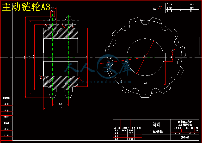
主动链轮A3.dwg

从动链轮A2.dwg

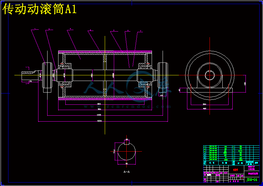
传动动滚筒A1.dwg

外文翻译--机器和机器零件的设计.doc

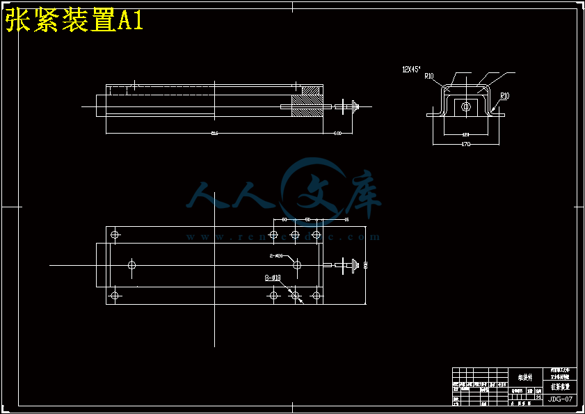
张紧装置A1.dwg

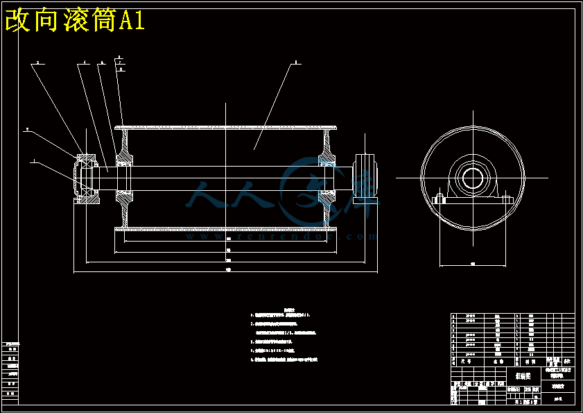
改向滚筒A1.dwg

新型甲带给料机设计开题报告.doc

新型甲带给料机设计说明书.doc

甲带给料机总装配图A1.dwg

缓冲托辊装置图A1.dwg

摘要

 甲带给料机,是用作各种料仓的给料设备。广泛用于煤矿、冶金、电力等行业各种料仓的给料选料与配料。它克服了以往振动给料机与往复式给料机(K3、K4式)的能耗大、噪声大、机械在工作中易疲劳等缺点,具有给料量连续可调、能耗低、低噪声、连续平稳运行、无明显疲劳现象出现等优点,从而满足现场高效、节能、降耗、环保、便捷的要求。

   其结构特征为:在料仓下导料槽的底部设一封闭的甲带,在一端甲带由驱动滚筒驱动,另一端设改向滚筒,中间设若干组托滚支承甲带;为取得更好的使用性能,可在甲带内设一封闭的胶带。本实用新型相比现有技术有以下优点:1.运行功率小,能量消耗少,运行经济性好;2.结构重量轻,造价低,运输方便;3.给料量大、稳定,且调整方便;4.运行平稳,噪音小,保护环境;5.磨损小,维修量小,使用寿命长;6.零部件通用性强,安装、维修简便;7.可更换现行的给料机。

关键词: 甲带给料机; 连续可调; 滚筒驱动; 优点; 维修简便。

Abstract

   A belt feeder is used for a variety of silo feeding equipment. Widely used in mining, metallurgy, electric power and other industries a variety of silo feeding choice of materials and ingredients. It overcomes the previous feeder and the reciprocating feeder (K3, K4 type) of the energy consumption, noise, machinery at work, fatigue and other shortcomings, continuously adjustable with a feeding amount, low energy consumption, low noise and continuous smooth operation, no obvious fatigue phenomenon, etc., to meet the on-site efficiency, energy conservation, energy, environmental protection, convenience requirements. Its structure: in the bin located under the guide of a trough at the bottom of a closed zone, a zone at one end by a drive pulley drive, set up the other end of bend pulley, the middle set up a number of groups of support with roller bearing; to achieve more good performance can be equipped with a tape of a closed. The utility model has the following advantages compared to existing technology: 1. Operating power is small, less energy consumption, running economy is good; 2. Structure, light weight, low cost, easy to transport; 3. To the feeding amount large, stable, and easy adjustment; 4. Smooth running, low noise, protect the environment; 5. Wear a small, small amount of maintenance, long service life; 6. Parts versatility, installation, maintenance is simple; 7. Replaceable current feeder.

目录

绪论1

1 甲带给料机概述3

1.1 甲带给料机的应用3

1.2 给料机的分类及特点4

1.2.1 槽式给料机4

1.2.2 圆盘给料机5

1.2.3 摆式给料机5

1.2.4 振动给料机5

1.2.5 电磁振动给料机5

1.2.6 甲带给料机6

1.3 甲带给料机的发展状况6

1.4 甲带给料机的工作原理8

1.5 甲带给料机的结构9

2  甲带给料机的设计计算10

2.1 已知原始数据及工作条件10

2.2 计算步骤11

2.2.1 带宽的确定11

2.3 圆周驱动力15

2.3.1 计算公式15

2.3.2 主要阻力计算17

2.3.3 主要特种阻力计算19

2.3.4 附加特种阻力计算20

2.3.5 倾斜阻力计算21

2.4 传动功率计算22

2.4.1 传动轴功率()计算22

2.4.2 电动机功率计算22

2.5 输送带张力计算23

2.5.1 输送带不打滑条件校核23

2.5.2 输送带下垂度校核24

2.5.3 各特性点张力计算25

2.6 传动滚筒、改向滚筒合张力计算27

2.6.1 改向滚筒合张力计算27

2.6.2 传动滚筒合张力计算27

2.7 传动滚筒最大扭矩计算28

2.8 拉紧力计算28

2.9绳芯输送带强度校核计算29

3 驱动装置的选用与设计30

3.1 电机的选用30

4 甲带给料机部件的选用33

4.1 甲带33

4.1.1 甲带的分类33

4.1.2 甲带的连接35

4.2 传动滚筒36

4.2.1 传动滚筒的作用及类型36

4.2.2 传动滚筒的选型及设计37

4.2.3 传动滚筒结构38

4.2.4 传动滚筒的直径验算39

4.3 托辊40

4.3.1 托辊的作用与类型40

4.3.2 托辊的选型43

4.4拉紧装置45

4.4.1 拉紧装置的作用45

4.4.2 张紧装置在使用中应满足的要求46

4.4.3 拉紧装置在过渡工况下的工作特点46

4.4.4 拉紧装置布置时应遵循的原则47

4.4.5 拉紧装置的种类及特点47

5 其他部件的选用50

5.1 机架与中间架50

5.2 给料装置53

5.2.1 对给料装置的基本要求53

5.2.2 装料段拦板的布置及尺寸53

5.2.3 装料点的缓冲54

5.3 卸料装置55

5.4清扫装置56

5.4.1 篦子式刮板清扫装置56

5.4.2 输送机式刮板清扫装置57

5.4.3 刷式清扫装置58

5.4.4 振动式清扫装置59

5.4.5 水力和风力清扫装置60

5.4.6 联合清扫装置61

5.4.7 清扫装置的种类及应用情况分析61

5.5 头部漏斗67

5.6 电气及安全保护装置67

致? 谢69

参考文献71

   甲带给料机是带式输送机的一种,是连续运行的运输设备,在冶金、采矿、动力、建材等重工业部门及交通运输部门中主要用来运送大量散状货物,如矿石、煤、砂等粉、块状物和包装好的成件物品。带式输送机是煤矿最理想的高效连续运输设备,与其他运输设备相比,不仅具有短距离、大运量、连续输送等优点,而且运行可靠,易于实现自动化、集中化控制,特别是对高产高效矿井,带式输送机已成为煤炭高效开采机电一体化技术与装备的关键设备。特别是近10年,大运量、高速度的带式输送机的出现,使其在矿山建设的井下巷道、矿井地表运输系统及露天采矿场、选矿厂中的应用又得到进一步推广。

   选择甲带给料机这种新型机械的设计作为毕业设计的选题,能培养我们独立解决工程实际问题的能力,通过这次毕业设计是对所学基本理论和专业知识的一次综合运用,也使我们的设计、计算和绘图能力都得到了全面的训练。

   原始参数:

   1) 输送物料:煤

   2) 物料特性:(1) 块度:0~80mm

           (2) 散装密度:0.90t/m3

           (3) 在输送带上堆积角:ρ=20°

           (4) 物料温度:<50℃

   3) 工作环境:井下

   4) 输送系统及相关尺寸:(1) 运距:4m

                 (2) 倾斜角:β=0°

                 (3) 最大运量:350t/h

   设计解决的问题:

   熟悉甲带给料机的各部分的功能与作用,对主要部件进行选型设计与计算,解决在实际使用中容易出现的问题,并大胆地进行创新设计。

   甲带给料机主要用于国民经济生产各部门物料传送系统中料仓的给料,它克服了目前给料系统中广泛使用的往复式和振动式给料机的缺点,改间断给料方式为连续给料方式,便恒定给料量为根据客户需要,大范围(给料量)动态连续可变给料,是给料系统更能满足高效、节能、环保的要求,此给料机可用于替换往复式和振动式给料机,还是用于跳汰机及装车仓的给料,此给料机可配备仓压检测装置,防止煤仓透风机物料对给料机的冲击。

   目前,料仓给料系统中所使用的给料机主要有K型往复式和震动式给料机,两种给料方式的给料机,其结构和工作原理是:在料仓下部设一导料槽,导料槽底板为活动式,用一动力装置带动底板循环往复运动,当底板向给料口方向运行时,物料随底板一起运动,完成给料过程;当底板向反方向运行时,物料在内压力及内外摩擦力的共同作用下,物料并不随底板一起运动;底板不断循环往复运动,仓内物料不断的被送往出料口。两种给料方式的不同点是,给料频率和幅值及运动轨迹的不同。

   K型往复式给料机的缺点是:给料机底板在回程中需要承受物料很大的摩擦力,所以需要较大的驱动功率,能耗大;由于功率大,结构受力也大,设备重量大;由于给料过程往复运动,设备震动大、噪音大;由于结构受力大,运动部件磨损快,维修量大;由于给料机不连续,生产率较低。

   振动式给料机的缺点是;由于给料频率高,噪声大;由于是靠高频震动给料,其振幅和频率受物料粒度及比重影响较大,所以给料量不稳定,给料量的调整页比较困难;由于是靠振动给料,给料机必须起震并稳定在一定的频率和振幅,但振动参数对底板受力状态很敏感,故底板不能承受较大的仓压,需增加仓下导料槽的长度,结果是增加了料仓的整体高度,是成本加大;由于给料高度加大,无法用于替换目前大量使用的K型往复式给料机。

   为克服上述给料机的缺陷,设计了一种甲带给料机,此给料机运行功率小,重量轻,给料量大,给料量稳定,调整方便,噪音小,维修量小,部件通用性强,且可用于更换目前正在使用的给料机的甲带给料机。

      1.2.1 槽式给料机

   槽式给料机可以架设于地面,也可以吊装在矿仓卸料口上。槽式给料机的槽体宽度约为给料最大粒度的2-2.5倍。最大的槽式给料机,可满足小于500mm粒度铁矿石的给矿。常选用的规格是980*1240槽式给料机,其给料粒度为350-0mm,适于作为400*600鄂式破碎机的给料设备。  槽底板作往复运动,其冲次为20-60次/min,冲程为20-200mm。冲程可由驱动装置偏心轮进行适当调整,偏心距为冲程之半。对于粘性矿石,偏心距不应小于30mm。

   1.2.2 圆盘给料机

   圆盘给料机是适用于20mm以下粉矿的给料设备。  圆盘式给料机由驱动装置、给料机本体、计量用带式输送机和计量装置组成。给料机和带式输送机由一套驱动装置驱动,该驱动装置的电磁离合器具有实现给料机的开、停和兼有功能转换的作用。计量带式输送机的带速小于1m/s,为了测定带速设有速度检测装置,为了防止称量辊偏斜设有检测杆进行调整。

   1.2.3 摆式给料机

   摆式给料机多作为球磨机集矿胶带输送机的给料设备。摆式给料机适用于选矿、选煤、化工及其他部门,将颗粒状物料从储料槽经漏斗送给各种类型的受料装置。摆式给料机不适宜输送干粉状或者太大粒度的物料,否则会出现粉尘污染及出料口堵塞现象1.3 甲带给料机的发展状况

   短距离、大运量、高速是带式输送机的发展方向之一。与其他运输设备相比,带式输送机不仅具有短距离、大运量、连续运输的特点,而且运行可靠,易于实现自动化和集中控制,经济效益十分明显。所以在企业的生产过程中,凡能实现带式输送机输送的场合,一般都采用连续的带式输送机输送。与其他设备相比,带式输送机有以下优点:

       (1) 输送物料种类广泛;

       (2) 输送能力范围宽;

       (3) 输送线路的适应性强;

       (4) 灵活的装卸料,可以灵活实现一点或多点受料或卸料;

       (5) 可靠性和安全性高;

       (6) 费用低。

   现代甲带带给料机的发展

   (1) 智能化

   为了适应高产高效集约化生产的需要,输送机的运输能力要加大,控制自动化水平要提高,高带速、大运量、大功率是带式输送机今后发展的必然趋势。

   (2)提高关键零部件的性能和可靠性

   设备开机率的高低主要取决于输送机关键零部件的性能和可靠性。而要提高关键零部件的性能和可靠性,除了进一步完善和提高现有零部件的性能和可靠性外,还要不断开发研究新的技术和零部件,如高性能可控软启动技术、动态分析与监控技术、高效储带装置、高寿命托辊等,使输送机的性能进一步提高。

   (3) 扩大功能,一机多用化

   甲带给料机是一种理想的连续中转运输设备,但目前其效能还没有充分发挥,资源有所浪费。如将带式输送机结构作适当修改,并采取一定的安全措施,就可拓展到运人、运料或双向运输等功能,做到一机多用,使其发挥最大的经济效益。

   (4) 电控与监测自动化技术

为了实现输送机可控启动、中间驱动、功率平衡、带速同步、自动张紧以及各种保护装置、通信与信号联络等综合功能的要求,开发了1.4 甲带给料机的工作原理

   料仓内的物料经连接段进入导料槽落在甲带上,甲带静止时物料最终靠内摩擦力而停止运动,在出料口形成一定角度的静止堆积;当驱动滚筒在外动力的驱动力下开始旋转时,带动胶带运动,胶带带动其上的物料导向出料口运行中的甲带在出料口卸料后转向回程,物料不断地从出料口排出,从而完成给料过程;二次密封装置对从导料槽和胶带之间间隙中露出的物料提供密封;粘结在甲带上未卸净物料在回程中,受重力、震动等因素的影响不断掉落于下护板上,而后又被甲带之甲片上凸起的刮料板再带回出料口重新卸料。改进进料口大小可通过闸板开度大小来实现;改变给料量,可以通过调节无级变速减速机的输出轴转速,来改变夹带运行速度的大小,从而改变给料量;改变给料量,也可以通过选配变频器,改变电动机转速,从而改变给料量。甲带给料机运行中,系统主要负荷均由滚筒轴承支撑,运行阻力小,设备所需驱动功率小,系统各零部件工作寿命长。5.5 头部漏斗

   头部漏斗用于导料、控制料流方向的装置。也可起防尘作用。

   (1) 本系列漏斗有普通型和调节挡板型(3型)两种。其中普通型又可分为不带衬板(1型)和带衬板(2型)两种。

   带速范围:≤2.5m/s(1型),3.15m/s(2型),调节挡板式带速范围1.6~5m/s;2型漏斗在水平运输时可达4m/s。

   (2) 订货时要注明清扫器的类型(重锤式或HP型刮板式等),以便确定漏斗上清扫器的安装孔。

   (3)  选用本系列漏斗时,设计者还应根据输送机之间的搭接高度设计漏斗与导料槽之间的联接段。  

5.6 电气及安全保护装置

   安全保护装置是在输送机工作中出现故障能进行监测和报警的设备,可使输送机系统安全生产,正常运行,预防机械部分的损坏,保护操作人员的安全。此外,还便于集中控制和提高自动化水平。

   (1) 电气及安全保护装置的设计、制造、运输及使用等要求,应符合有关国家标准或专业标准要求,如IEC439《低压开关设备和控制装置》;GB4720《装有低压电器的电控设备》;GB3797《装有电子器件的电控设备》。

   (2) 电气设备的保护:主回路要求有电压、电流仪表指示器,并有断路、短路、过流(过载)、缺相、接地等项保护及声、光报警指示,指示器应灵敏、可靠。

   (3) 安全保护和监测;应根据输送机输送工艺要求及系统或单机的工况进行选择,常用的保护和监测装置如下:

   a.输送带跑偏监测:一般安装在输送机头部、尾部、中间及需要监测的点,轻度跑偏量达5%带宽时发出信号并报警,重度跑偏量达l 0%带宽时延时动作,报警、正常停机。

   b.打滑监测:用于监视传动滚筒和输送带之间的线速度之差,并能报警、自动张紧输送带或正常停机。

   c.超速监测:用于下运或下运工况,当带速达到规定带速的l15%~l25%时报警并紧急停机。

   d.沿线紧急停机用拉绳开关,沿输送机全长在机架的两侧每隔60m各安装—组开关,动作后自锁、报警、停机。

   e.其他料仓堵塞信号、纵向撕裂信号及拉紧、制动信号、测温信号等,可根据需要进行选择。

   1.2.4 振动给料机

   振动给料机又称振动喂料机。振动给料机可把块状、颗粒状物料从贮料仓中均匀、定时、连续地给到受料装置中去,在砂石生产线中可为破碎机械连续均匀地喂料,并对物料进行粗筛分,振动给料机广泛用于冶金、煤矿、选矿、建材、化工、磨料等行业的破碎、筛分联合设备中。    振动给料机(喂料机)性能特点:振动平稳、工作可靠、寿命长;可以调节激振力,可随时改变和控制流量,调节方便稳定;振动电机为激振源,噪声低,耗电小,调节性能好,无冲料现象。结构简单,运行可靠,调节安装方便,重量轻,体积小,维护保养方便,当采用封闭式结构机身时可防止粉尘污染。

   1.2.5 电磁振动给料机

   电磁振动给料机是一种较新型的定量给料设备,能适应于连续性生产的要求,其结构简单, 操作方便,不需润化,耗电量小;可以均匀地调节给矿量;因此已得到广泛应用,用于把块状、颗粒状及粉体状物料从贮料仓或漏斗中定量均匀连续地给到受料装置中,可作为带式输送机、斗式提升机、筛分设备水泥磨机、破碎机、粉碎机及各工业部门粘滞性的颗粒粉末状的供料装置;用于自动配料,定量包装等,并经可用于自动控制的流程中,实现生产流程的自动化。一般用于松散物料。广泛用于矿石、冶金、煤炭、建材、轻工、化工、电力、机械粮食、医药等工矿企业生产环节中。

   1.2.6 甲带给料机

   甲带给料机主要用于国民经济生产各部门物料传送系统中料仓的给料,甲带给料机为连续给料方式,恒定给料量刻根据客户需要,大范围(给料量)动态连续可变给料,是给料系统更能满足高效、节能、环保的要求,在煤矿中使用,可配备仓压检测装置,防止煤仓透风机物料对给料机的冲击。

   甲带给料机的特点:运行功率小,重量轻,给料量大,给料量稳定,调整方便,噪音小,维修量小,部件通用性强。

参考文献

   [1] 机械工程手册、电机工程手册编辑委员会.机械工程手册—机械产品(二)[M].机械工业出版社.1982年8月.

   [2] 范祖尧等.现代机械设备设计手册—非标准机械设备设计[M].机械工业出版社.2000年6月.

   [3] 唐金松.简明机械设计手册(第二版)[M].上海科学技术出版社.2002年6月.

   [4] 北京起重机机械研究所、武汉丰凡科技开发有限责任公司.DTⅡ(A)型带式输送机机械设计手册[M].冶金工业出版社.2003年8月.

   [5] 机械工业部设计单位联合设计组.ZJT1A-96带式输送机设计选用手册[M].黄河水利出版社.1998年10月.

   [6] 机械化运输设计手册编委会.机械化运输设计手册[M].机械工业出版社.1997年5月.

   [7] 张钺.新型带式输送机设计手册[M].冶金工业出版社.2001年2月.

   [8]《运输机械设计选用手册》编组委.运输机械设计选用手册(上、下)[M].化学工业出版社.1999年1月.

   [9] 毋虎城.矿山运输与提升设备[M].煤炭工业出版设.2004年5月.

   [10] 上海煤矿机械研究所.煤矿机械设计手册[M].1972年.

   [11] 于学谦.矿山运输机械[M].中国矿业大学出版社,1998年.

   [12] 北起所.DTⅡ型带式输送机设计选用手册[M].冶金工业出版社.1994年.

   [13] 北起所.DTⅡ型带式输送机平行轴驱动装置设计选用手册[M].机械工业部.1997年.

   [14] 孔庆华,刘传绍.极限测量与测试技术基础[M].同济大学出版社.2002年.

   [15] 机械设计手册编写组.机械设计手册[M].化学工业出版社.2002年.

   [16] 中国纺织大学工程图学教研室.画法几何及工程制图[M].上海科技出版社.2000年.

   [17] 张文芳,段志强,边会杰.带式输送机防跑偏辊及清扫器的使用与研究[J].  河北煤炭.2002,5:9-10.

   [18] 尹万涛,胡述记,米迎春.带式输送机自动调偏装置的改进设计[J].郑煤科技.2005,3:42-44.

   [19] 李红玉.带式输送机自动调偏滚筒.矿业快报.2004,4(4):36.

   [20] 张广文.起井下胶带输送机火灾事故的剖析与经验教[J].煤矿安全,2001,32(10):46-47.

   [21] 李铁东,姜卫东.西沟矿下运带式输送机系统的设计及应用[J].煤矿机械,2004(9):8-9.

   [22] 刘训涛,毛君.带式输送机断带抓捕器研究[J].矿山机械,2005(2):41-42.

   [23]毛君,刘训涛.带式输送机断带保护系统的研究[J].煤矿机械,2004,(11):99-100.

   [24] 陈炳耀,祁开阳.带式输送机输送带与滚筒之间的打滑分析[J].煤矿机械,2003(5):49-51.

   [25] 罗云.21世纪安全管理科学展望[J].中国安全科学学报,2000,10(1):27-31.

   [26] 禹金云.机械安全技术趋向分析[J].中国安全科学学报,2004,14(4):54-56.

   [27] 王传海,张卫国.带式输送机断带及飞车制动保护装置[J].矿业安全与环保2003,30(3):40-46.

   [28] 史志远,朱真才.带式输送机断带保护装置分析[J].煤矿机械,2005(8):83-85.

   [29] 贺建华,鹿守明,丁永红.变频启动器在煤矿带式输送机上的应用[J].工矿自 动化.2006,12(6):56-58.

   [30] 颜传宝,胡少银.软起动和液力偶合器配合使用及在带式输运机传动中的应用[J].煤矿机电.2003,334-36.

内容简介:
河南理工大学万方科技学院本科毕业设计(论文)中期检查表指导教师:陈东海 职称: 副教授 所在院(系):机械与动力工程系 教研室(研究室):机械学院401室 题 目新型带式给料机学生姓名徐明辉专业班级07机设(1)班学号0720150060一、 选题质量:1, 该选题为新型带式给料机的设计,这可以对我大学四年所学知识进行一次较为全面的练习。2,题目的难易程度适中,并且是多个行业常用设备,是我们熟悉的课题。 2, 题目的工作量:要求完成3张以上的A0图纸,2.53万的说明书一份。4,所选题目紧密结合着生产实际,在我的专业范围之内,这必对我以后从事的生产和实践工作有很大的帮助。 二、 开题报告完成情况:结合现在的新技术和新设备等方面资料的搜集,通过对可行性的分析,我认真的进行了这次毕业设计的选题。选此题目以后,针对这个设计的题目我认真的查阅了相关的资料,最后结合所有的材料和设计任务完成开题报告。三、阶段性成果:1通过对新型带式给料机的整体了解,在加上指导老师的仔细讲解,我对本次毕业设计的课题有了较为深入的理解,现在我已收集了大量的资料和文献,为设计的顺利完成做好了充分的准备。2. 在老师的指导和同学的帮助下找到了设计的基本方法,开始了一些基本的结构设计。3. 正在进行装配图的CAD画图。四、存在主要问题:这次是我第一次系统的进行设计,所以在刚开始时有些茫然不知如何着手,设计工作做的很不顺利,后来找了指导老师,老师对此进行了仔细的讲解,并与本组同学进行了商量,我逐渐找到是设计的切入点,我觉得这对我以后设计工作的顺利进行有很大的帮助。随着设计的逐渐进行我又遇到了许多的新的更加复杂的问题,这些问题使我充分认识到了自己在以前学习中的不足和差距,所以我要以本次设计为契机加强自己薄弱环节的学习,争取使我的毕业设计能够取得好的成绩,也使我所学的知识能够在以后的工作中发挥更大的作用。五、指导教师对学生在毕业实习中,劳动、学习纪律及毕业设计(论文)进展等方面的评语指导教师: (签名) 年 月 日Machine designMachine design is the art of planning or devising new or improved machines to accomplish specific purposes. In general, a machine will consist of a combination of several different mechanical elements properly designed and arranged to work together, as a whole. During the initial planning of a machine, fundamental decisions must be made concerning loading, type of kinematic elements to be used, and correct utilization of the properties of engineering materials. Economic considerations are usually of prime importance when the design of new machinery is undertaken. In general, the lowest over-all costs are designed. Consideration should be given not only to the cost of design, manufacture the necessary safety features and be of pleasing external appearance. The objective is to produce a machine which is not only sufficiently rugged to function properly for a reasonable life, but is at the same time cheap enough to be economically feasible. The engineer in charge of the design of a machine should not only have adequate technical training, but must be a man of sound judgment and wide experience, qualities which are usually acquired only after considerable time has been spent in actual professional work. Design of machine elements The principles of design are, of course, universal. The same theory or equations may be applied to a very small part, as in an instrument, or, to a larger but similar part used in a piece of heavy equipment. In no ease, however, should mathematical calculations be looked upon as absolute and final. They are all subject to the accuracy of the various assumptions, which must necessarily be made in engineering work. Sometimes only a portion of the total number of parts in a machine are designed on the basis of analytic calculations. The form and size of the remaining parts are designed on the basis of analytic calculations. On the other hand, if the machine is very expensive, or if weight is a factor, as in airplanes, design computations may then be made for almost all the parts. The purpose of the design calculations is, of course, to attempt to predict the stress or deformation in the part in order that it may sagely carry the loads, which will be imposed on it, and that it may last for the expected life of the machine. All calculations are, of course, dependent on the physical properties of the construction materials as determined by laboratory tests. A rational method of design attempts to take the results of relatively simple and fundamental tests such as tension, compression, torsion, and fatigue and apply them to all the complicated and involved situations encountered in present-day machinery. In addition, it has been amply proved that such details as surface condition, fillets, notches, manufacturing tolerances, and heat treatment have a market effect on the strength and useful life of a machine part. The design and drafting departments must specify completely all such particulars, must specify completely all such particulars, and thus exercise the necessary close control over the finished product. As mentioned above, machine design is a vast field of engineering technology. As such, it begins with the conception of an idea and follows through the various phases of design analysis, manufacturing, marketing and consumerism. The following is a list of the major areas of consideration in the general field of machine design: Initial design conception; Strength analysis; Materials selection; Appearance; Manufacturing; Safety; Environment effects; Reliability and life; Strength is a measure of the ability to resist, without fails, forces which cause stresses and strains. The forces may be; Gradually applied; Suddenly applied; Applied under impact; Applied with continuous direction reversals; Applied at low or elevated temperatures. If a critical part of a machine fails, the whole machine must be shut down until a repair is made. Thus, when designing a new machine, it is extremely important that critical parts be made strong enough to prevent failure. The designer should determine as precisely as possible the nature, magnitude, direction and point of application of all forces. Machine design is mot, however, an exact science and it is, therefore, rarely possible to determine exactly all the applied forces. In addition, different samples of a specified material will exhibit somewhat different abilities to resist loads, temperatures and other environment conditions. In spite of this, design calculations based on appropriate assumptions are invaluable in the proper design of machine. Moreover, it is absolutely essential that a design engineer knows how and why parts fail so that reliable machines which require minimum maintenance can be designed. Sometimes, a failure can be serious, such as when a tire blows out on an automobile traveling at high speeds. On the other hand, a failure may be no more than a nuisance. An example is the loosening of the radiator hose in the automobile cooling system. The consequence of this latter failure is usually the loss of some radiator coolant, a condition which is readily detected and corrected. The type of load a part absorbs is just as significant as the magnitude. Generally speaking, dynamic loads with direction reversals cause greater difficulties than static loads and, therefore, fatigue strength must be considered. Another concern is whether the material is ductile or brittle. For example, brittle materials are considered to be unacceptable where fatigue is involved. In general, the design engineer must consider all possible modes of failure, which include the following: Stress; Deformation; Wear; Corrosion; Vibration; Environmental damage; Loosening of fastening devices. The part sizes and shapes selected must also take into account many dimensional factors which produce external load effects such as geometric discontinuities, residual stresses due to forming of desired contours, and the application of interference fit joint. Selected from” design of machine elements”, 6th edition, m. f. sports, prentice-hall, inc., 1985 and “machine design”, Anthony Esposito, charles e., Merrill publishing company, 1975.Mechanical properties of materials The material properties can be classified into three major headings: (1) physical, (2) chemical, (3) mechanicalPhysical properties Density or specific gravity, moisture content, etc., can be classified under this category. Chemical propertiesMany chemical properties come under this category. These include acidity or alkalinity, react6ivity and corrosion. The most important of these is corrosion which can be explained in laymans terms as the resistance of the material to decay while in continuous use in a particular atmosphere. Mechanical properties Mechanical properties include in the strength properties like tensile, compression, shear, torsion, impact, fatigue and creep. The tensile strength of a material is obtained by dividing the maximum load, which the specimen bears by the area of cross-section of the specimen.This is a curve plotted between the stress along the This is a curve plotted between the stress along the Y-axis(ordinate) and the strain along the X-axis (abscissa) in a tensile test. A material tends to change or changes its dimensions when it is loaded, depending upon the magnitude of the load. When the load is removed it can be seen that the deformation disappears. For many materials this occurs op to a certain value of the stress called the elastic limit Ap. This is depicted by the straight line relationship and a small deviation thereafter, in the stress-strain curve (fig.3.1). Within the elastic range, the limiting value of the stress up to which the stress and strain are proportional, is called the limit of proportionality Ap. In this region, the metal obeys hookess law, which states that the stress is proportional to strain in the elastic range of loading, (the material completely regains its original dimensions after the load is removed). In the actual plotting of the curve, the proportionality limit is obtained at a slightly lower value of the load than the elastic limit. This may be attributed to the time-lagin the regaining of the original dimensions of the material. This effect is very frequently noticed in some non-ferrous metals. Which iron and nickel exhibit clear ranges of elasticity, copper, zinc, tin, are found to be imperfectly elastic even at relatively low values low values of stresses. Actually the elastic limit is distinguishable from the proportionality limit more clearly depending upon the sensitivity of the measuring instrument. When the load is increased beyond the elastic limit, plastic deformation starts. Simultaneously the specimen gets work-hardened. A point is reached when the deformation starts to occur more rapidly than the increasing load. This point is called they yield point Q. the metal which was resisting the load till then, starts to deform somewhat rapidly, i. e., yield. The yield stress is called yield limit Ay. The elongation of the specimen continues from Q to S and then to T. The stress-strain relation in this plastic flow period is indicated by the portion QRST of the curve. At the specimen breaks, and this load is called the breaking load. The value of the maximum load S divided by the original cross-sectional area of the specimen is referred to as the ultimate tensile strength of the metal or simply the tensile strength Au. Logically speaking, once the elastic limit is exceeded, the metal should start to yield, and finally break, without any increase in the value of stress. But the curve records an increased stress even after the elastic limit is exceeded. Two reasons can be given for this behavior: The strain hardening of the material; The diminishing cross-sectional area of the specimen, suffered on account of the plastic deformation. The more plastic deformation the metal undergoes, the harder it becomes, due to work-hardening. The more the metal gets elongated the more its diameter (and hence, cross-sectional area) is decreased. This continues until the point S is reached. After S, the rate at which the reduction in area takes place, exceeds the rate at which the stress increases. Strain becomes so high that the reduction in area begins to produce a localized effect at some point. This is called necking. Reduction in cross-sectional area takes place very rapidly; so rapidly that the load value actually drops. This is indicated by ST. failure occurs at this point T. Then percentage elongation A and reduction in reduction in area W indicate the ductility or plasticity of the material: A=(L-L0)/L0*100% W=(A0-A)/A0*100% Where L0 and L are the original and the final length of the specimen; A0 and A are the original and the final cross-section area.机器和机器零件的设计机器设计机器设计为了特定的目的而发明或改进机器的一种艺术。一般来讲,机器时有多种不同的合理设计并有序装配在一起的部件构成的,在最初的机器设计阶段,必须基本明确负载、元件的运动情况、工程材料的合理使用性能。负责新机器的设计最初的最重要的是经济性考虑。一般来说,选择总成本最低的设计方案,不仅要考虑设计、制造、销售、安装的成本。还要考虑服务的费用,机械要保证必要的安全性能和美观的外形。制造机器的目标不仅要追求保证只用功能的合理寿命,还要保证足够便宜以同时保证其经济的可行性。负责设计机器的工程师,不仅要经过专业的培训,而且必须是一个准确判断而又有丰富经验的人,具有一种有足够时间从事专门的实际工作的素质。机器零件的设计相同的理论或方程可应用在一个一起的非常小的零件上,也可用在一个复杂的设备的大型相似件上,既然如此,毫无疑问,数学计算是绝对的和最终的。他们都符合不同的设想,这必须由工程量决定。有时,一台机器的零件全部计算仅仅是设计的一部分。零件的结构和尺寸通常根据实际考虑。另一方面,如果机器和昂贵,或者质量很重要,例如飞机,那麽每一个零件都要设计计算。当然,设计计算的目的是试图预测零件的应力和变形,以保证其安全的带动负载,这是必要的,并且其也许影响到机器的最终寿命。当然,所有的计算依赖于这些结构材料通过试验测定的物理性能。国际上的设计方法试图通过从一些相对简单的而基本的实验中得到一些结果,这些试验,例如结构复杂的及现代机械设计到的电压、转矩和疲劳强度。另外,可以充分证明,一些细节,如表面粗糙度、圆角、开槽、制造公差和热处理都对机械零件的强度及使用寿命有影响。设计和构建布局要完全详细地说明每一个细节,并且对最终产品进行必要的测试。综上所述,机械设计是一个非常宽的工程技术领域。例如,从设计理念到设计分析的每一个阶段,制造,市场,销售。以下是机械设计的一般领域应考虑的主要方面的清单:最初的设计理念 受力分析 材料的选择 外形 制造 安全性 环境影响 可靠性及寿命在没有破坏的情况下,强度是抵抗引起应力和应变的一种量度。这些力可能是:渐变力 瞬时力 冲击力 不断变化的力 温差如果一个机器的关键件损坏,整个机器必须关闭,直到修理好为止。设计一台新机器时,关键件具有足够的抵抗破坏的能力是非常重要的。设计者应尽可能准确地确定所有的性质、大小、方向及作用点。机器设计不是这样,但精确的科学是这样,因此很难准确地确定所有力。另外,一种特殊材料的不同样本会显现出不同的性能,像抗负载、温度和其他外部条件。尽管如此,在机械设计中给予合理综合的设计计算是非常有用的。此外,显而易见的是一个知道零件是如何和为什麽破坏的设计师可以设计出需要很少维修的可靠机器。有时,一次失败是严重的,例如高速行驶的汽车的轮胎爆裂。另一方面,失败未必是麻烦。例如,汽车的冷却系统的散热器皮带管松开。这种破坏的后果通常是损失一些散热片,可以探测并改正过来。零件负载类型是一个重要的标志。一般而言,变化的动负载比静负载会引起更大的差异。因此,疲劳强度必须符合。另一个关心的方面是这种材料是否直或易碎。例如有疲劳破坏的地方不易使用易碎的材料。一般的,设计师要靠考虑所有破坏情况,其包括以下方面:应力 应变 外形 腐蚀 震动 外部环境破坏 紧固件的松脱零件的尺寸和外形的选择也有很多因素。外部负荷的影响,如几何间断,由于轮廓而产生的残余应力和组合件干涉。选自机械元件设计第六版,斯鲍特、普瑞特斯等,1985年和机械设计埃斯普特斯、查里斯、麦瑞欧出版公司,1975年。材料的机械性能的机械性能可以被分成三个方面:物理性能,化学性能,机械性能。物理性能密度或比重、温度等可以归为这一类。化学性能这一种类包括很多化学性能。其中包括酸碱性、化学反应性、腐蚀性。其中最重要的是腐蚀性,在外行人看来,腐蚀性被解释为在某处的零件抵抗腐蚀的能力。机械性能机械性能包括拉伸性能、压缩性能、剪切性能、扭转性能、冲击性能、疲劳性能和蠕变。材料的拉伸强度可以通过试件的横截面积出试件承受的最大载荷得到,这是在拉伸试验中,应力沿Y轴,应边沿X轴变化的曲线。一种材料加载时开始发生变化的初值取决于负载的大小。当负载去掉时可以看到变形消失。对于很多材料而言,在达到弹性极限的一定应力值A之前,一直表现为这样。在应力-应变图中,这是可以用线性关系来描述的。这之后又一个小的偏移。在弹性范围内,达到应力的极限之前,应力和应变是成比例的,这被称为比例极限Ap。在这个区域,零件符合胡克定律,即应力与应变是成比例的,在弹性范围内(材料能完全恢复到最初的尺寸,当负载去掉时)。曲线中的实际点,比例极限在弹性极限处。这可以认为是材料恢复初值时落后于前者。这种影响在不含铁的材料中经常提到。铁和镍有明显的弹性范围,而铜、锌、锡等,即使在相对低的应力下也表现为不完全弹性。实际上,能否清楚地分辩弹性极限和比例极限取决于测量设备的灵敏度。当负载超过弹性极限时,塑性变形开始,逐渐的试件被硬化。变形比负载增加得更快时的点被称成为屈服点Q。金属开始抵抗负载转变成快速变形,这时的屈服力成为屈服极限Ay。试件的延伸率 继续由Q到T再到,在这种塑性流动时,应力应变关系在曲线上处于QRST区域。在点,试件破坏且这种负载称为破坏负载。最大负载S除以试件初始的截面积,被定义为这种金属的最终拉伸极限或试样的拉伸强度Au。按逻辑说,在应力不增加的情况下,一旦超出弹性极限,金属开始屈服,并最终破坏。但是当超出弹性极限后,在纪录曲线上应增大。这种变化主要有两个原因:材料的应力硬化由于塑性变形而引起的试件横截面积的变小由于加工硬化,金属塑性变化越大,硬化越严重。金属拉伸越长,他的直径(横截面积)越小。直到到达点为止。点之后,减少的速率开始变化,超过了应力增加的速率,应变很大以至于在局部的某些点的面积减少,被称为颈缩。横截面积减少得非常快,以至于抗负载的能力下降,即ST阶段。破坏发生在T点。延伸率A和截面积变化率u被描述成材料的延展性和塑性:a=(L0-L)/L0*100%u=(A0-A)/A0*100%在这里,L0和L分别是试件的最初和最终长度,A0和A分别是试件的最初截面积和最终截面积。5河南理工大学本科毕业设计(论文)开题报告题目名称新型甲带给料机学生姓名徐明辉专业班级07机设1班学号0720150060一、 选题的目的和意义:毕业设计是我们大学学习生活最后的一项重要学习任务,通过本次毕业设计,培养学生综合运用液压传动、机械设计、工程理学等课程中所学理论知识的能力;强调设计的独创性和实用性,培养和提高设
温馨提示:
1: 本站所有资源如无特殊说明,都需要本地电脑安装OFFICE2007和PDF阅读器。图纸软件为CAD,CAXA,PROE,UG,SolidWorks等.压缩文件请下载最新的WinRAR软件解压。
2: 本站的文档不包含任何第三方提供的附件图纸等,如果需要附件,请联系上传者。文件的所有权益归上传用户所有。
3.本站RAR压缩包中若带图纸,网页内容里面会有图纸预览,若没有图纸预览就没有图纸。
4. 未经权益所有人同意不得将文件中的内容挪作商业或盈利用途。
5. 人人文库网仅提供信息存储空间,仅对用户上传内容的表现方式做保护处理,对用户上传分享的文档内容本身不做任何修改或编辑,并不能对任何下载内容负责。
6. 下载文件中如有侵权或不适当内容,请与我们联系,我们立即纠正。
7. 本站不保证下载资源的准确性、安全性和完整性, 同时也不承担用户因使用这些下载资源对自己和他人造成任何形式的伤害或损失。
提示  人人文库网所有资源均是用户自行上传分享,仅供网友学习交流,未经上传用户书面授权,请勿作他用。
关于本文
本文标题:新型甲带给料机设计【6张CAD图纸】【优秀】
链接地址:https://www.renrendoc.com/p-295605.html

官方联系方式

2:不支持迅雷下载,请使用浏览器下载   
3:不支持QQ浏览器下载,请用其他浏览器   
4:下载后的文档和图纸-无水印   
5:文档经过压缩,下载后原文更清晰   
关于我们 - 网站声明 - 网站地图 - 资源地图 - 友情链接 - 网站客服 - 联系我们

网站客服QQ:2881952447     

copyright@ 2020-2025  renrendoc.com 人人文库版权所有   联系电话:400-852-1180

备案号:蜀ICP备2022000484号-2       经营许可证: 川B2-20220663       公网安备川公网安备: 51019002004831号

本站为文档C2C交易模式,即用户上传的文档直接被用户下载,本站只是中间服务平台,本站所有文档下载所得的收益归上传人(含作者)所有。人人文库网仅提供信息存储空间,仅对用户上传内容的表现方式做保护处理,对上载内容本身不做任何修改或编辑。若文档所含内容侵犯了您的版权或隐私,请立即通知人人文库网,我们立即给予删除!