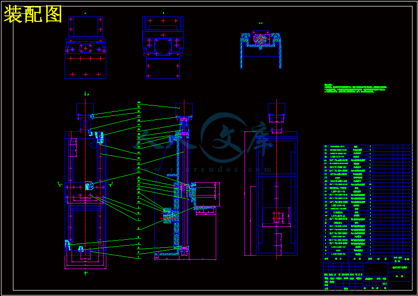
配重块.dwg
配重块.dwg

激光测量机纵轴传动机构设计【4张CAD图纸】【优秀】

收藏

压缩包内文档预览:
预览图
编号:295742    类型:共享资源    大小:1.15MB    格式:RAR    上传时间:2014-07-11 上传人:上*** IP属地:江苏
45
积分
关 键 词:
激光 测量机 纵轴 传动机构 设计 cad图纸
资源描述:

激光测量机纵轴传动机构设计

31页 14000字数+说明书+任务书+开题报告+外文翻译+4张CAD图纸【详情如下】

中期检查表.doc

内封面.docx

前期工作材料封面.doc

外文翻译--MSC软件公司通过仿真软件工具.doc

实习报告.docx

审题表和任务书.doc

封面本.doc

激光测量机纵轴传动机构设计开题报告.doc

激光测量机纵轴传动机构设计论文.docx

电机座.dwg

装配图.DWG

连接块.dwg

配重块.dwg

中文摘要

   随着工业现代化进程的发展,伴随着众多制造业如汽车业等大规模生产的需要,在加工设备提高功效、自动化更强的基础上,要求计量检测手段应当高速、柔性化、通用化,而固定的、专用的或手动的工量具大大限制了大批量制造和复杂零件加工业的发展;平板加高度尺加卡尺的检验模式已完全不适用现代化柔性制造和更多复杂形状工件的测量需要,所有这些促进和推动了近代坐标测量技术的发展。三坐标测量机作为一种测量仪器,越来越广泛的应用于制造,电子,汽车和航天等工业中,而且成为不可缺少的组成部分,对各种空间自由曲面等复杂形面的检测尤为适用。三坐标测量技术自从20实际60年代发展以来,已经逐渐成熟,现主要向高效率,高精度非接触式方向发展。本文主要以三坐标测量机为研究对象,概述了测量机的基本原理及基本组成,描述坐标测量机的结构、特点及发展方向,重点讨论了激光测距式非接触三坐标测量机纵轴传动机构的选用及实现。

关键词:测量,三坐标测量机,传动机构

Abatract

   Wish the denelopment of industrial modernization process, along with many manufacturing industries such as automotive industry’s needs for large-scale production, on the basis of increasing efficiency in the processing equipment, and stronger automation, their measurement requirements should be high speed, flexible and universal but fixed appropriative and hand used tools greatly limited the high-volume and complex parts manufacturing industries’ development; the test model of plate, height ruler and calipers does not fully apply modern flexible manufacturing and more complex forms part of the measurement needs, all of which promote and facilitate the modern coordinate measurement technology. CMM as measuring instrument, is more and more more widely used in manufacturing, electronics, automotive, aerospace and other industries, and is becoming an indispensable part. And it is particularly applicable in the complex-free surface space text. The CMM technology developed since the 1960s, have gradually matured, it is mainly to the high efficiency, high-precision non-contact direction. This article mainly talked about the coordinate measuring machine, summarized the basic principles of measuring machines and basic components, described the CMM structure, characteristics and development, focused on how to chose and realize the transmission mechanism of the non-contact Laser-Ranging-CMM.

Key words: Measurement, CMM, The transmission mechanism

目  录

中文摘要

Abatract

绪论1

  1.1 三坐标测量机的简述1

  1.2 坐标测量机的基本组成1

  1.3 三坐标测量机的结构1

  1.4 激光测量机系统结构及测量过程3

  1.5 国内外概况3

   1.5.1 国外概况3

   1.5.2 国内概况4

  1.6 设计概述5

第二章 设计说明6

  2.1 立柱设计6

   2.1.1 立柱的作用及特点6

   2.1.2 材料选用7

  2.2 传动机构设计8

   2.2.1 机构选用8

   2.2.2 滚珠丝杠副的安装10

   2.2.3 滚珠丝杠副的防护和润滑11

  2.3 轴承选用12

  2.4 导轨副的选用13

   2.4.1 直线导轨副结构形式13

   2.4.2 材料、热处理及防护14

  2.5 装配15

  2.6 主要参数的设定15

第三章 设计计算17

  3.1 Y轴滚珠丝杠副的选择计算17

第四章 三坐标测量机的未来展望24

总结

致谢

参考文献

附录

三坐标测量机的简述

   三坐标测量机CMM(3D Coodinate Measuring Machine)简称测量机。它是以精密机械为基础,综合应用光学、电子技术、计算机技术等先进技术的测量仪器。

   任何形状都是由空间点组成,所有的几何量测量都可以归结为空间点的测量,因此精确进行空间点坐标的采集,是评定任何几何形状的基础。坐标测量机的基本原理就是将被测零件放入它允许的测量空间,精确的测出被测零件表面的点在空间三个坐标位置的数值,将这些点的坐标数值经过计算机数据处理,拟和形成测量元素,如圆、球、圆柱、圆锥、曲面等,经过数学计算的方法得出其形状、位置公差及其他几何量数据。

   近几十年来,由于现代工艺技术的进步(计算机、集成电路、新材料、气浮技术、传感技术等),促进了三坐标测量机(CMM)的发展。它不仅能测量箱体、汽缸盖、涡轮、叶片、齿轮、凸轮、模具、各种机身型体及不规则空间型面的零件,而且还可以配合数控机、加工中心和柔性制造系统(FMS)纳入制造工程,并和CAT、CAD、CAM组成联机集成系统,以实现设计、制造和检测一体化。

1.2坐标测量机的基本组成

   测量机一般由主机、电子系统、软件系统及探测系统所组成。主机包括了其上附属的装置如光栅、电机等;电气系统包括电控柜及计算机;测量软件形式很多,如通用软件、统计分析软件等,由于误差补偿技术的发展及算法和控制软件的改进,测量机精度在很大精度上依赖于软件;探测系统是有测头及其附件组成的系统,测头是坐标测量机的关键部件,测头精度的高低很大程度决定了测量机的测量重复性及精度。

1.3三坐标测量机的结构

   三坐标测量机有不同的操作需求、测量范围和测量精度,这些对选用三坐标测量机是很重要的。各种类型的三坐标测量机结构外形叙述如下: 

   图1.1 三坐标测量机结构

(1)悬臂式:前面开阔,耗材少,但受刚性影响大。立柱横梁受力变形影响精度。适用于中小型机。

(2)活动水平臂式:测量空间大,立柱运动方向可以充分加长,但由于水平轴受变形的影响较大,长度受到一定限制。

(3)固定水平臂式:可以比较方便地修正因立柱和水平臂运动引进的阿贝误差,工作台承载能力不能太大。适用于小型机。

(4)单柱式:立柱运动与水平运动分开,可以达到较高的精度。由于具有二维水平运动的工作台加工复杂,难于推广。适合小型机或稍大一些的机型。

(5)移动龙门式:工作台承载能力大,不影响运动部件的精度,但由于横梁上的运动部件影响移动龙门的重心,加之绝大部分生产厂龙门架为开口状且为单边驱动,影响运动刚性,扭转也大,最终影响测量机的稳定性和测量精度。

(6)固定龙门式:整机刚性好,负载变化时机械变型小,可以在中央驱动工作台,可以通过适当加大固定龙门的体积来提高龙门上运动部件的运动精度,半闭式气浮导轨刚性好。缺点是承载不能太大,不利于发展高速测量机。适用于中小型机型。

(7)L型桥式:与移动龙门所存在的问题相似,现很少被采用。

(8)高架桥式:由于运动部件被架在两个固定龙门之间,当运动部件采用高强度轻型材料时,运动性能可以优于移动龙门式,更利于发展高速测量机,整机结构简单。适用于中型和大型机。

1.4激光测量机系统结构及测量过程

   激光非接触式三坐标测量系统主要由:三维扫描机构、激光非接触测量头及对准装置、控制系统和数据处理系统等四部分组成。它实质上是由一个水平X轴、一个垂直Y轴、一个回转工作台加上CCD激光测量头等构成的特别适合回转体高速非接触测量的三坐标机。

   系统工作过程为:主控程序先完成系统的初始化,然后把被测量部件放在转台上,在测量过程中转台一直匀速旋转。测量从最底圈开始,一圈一圈测量。当测量一圈时,主控程序启动控制模块控制横梁和滑动臂沿水平及垂直方向运动,使得测量点在测量头的测量范围内,然后转头旋转,使得测量头对准被测部件。转头运动完毕后,运动控制模块通知主控程序运动结束,然后由主控程序启动数据采集模块。数据采集模块在高精度定时线程的控制下进行数据采集。当测量完一圈后,数据采集模块暂停,同时通知主控程序完成一圈数据采集。这时候主控制程序再启动运动控制模块 来调整测量头的位置,准备测量下一圈。这样一直测量到最后一圈,然后系统复位。数据利用串行化技术存储,以供数据处理程序处理。

1.5 国内外概况

   三坐标测量机属于高精度测量仪器,在行业内已经有大约50年的发展历史。三坐标测量机主要应用于机械制造、汽车、航空、模具制造等工业生产行业中,在工业生产过程中发挥着非常重要的作用。随着高新技术和计算机应用技术的发展,三坐标测量机技术也得到了长足的发展空间。

1.5.1国外概况

国外三坐标测量机生产厂家较多,系列品种很多,大多数都有划线功能。注明的国外生产厂家有德国Zeiss和Leitz、意大利的DEA、美国的布朗-夏普、日本的三丰等公司。

总的来说,国外机器油一下特点:(1)绝大多数机器总体布局为悬臂式,空间敞开性好,便于安装大的零件或整车;(2)采用“AutoCAD”和有限元法进行优化设计,结构较合理,造型优美;(3)专项开发力量强,专用软件和附件较多,能满足更多用户的特殊需要;(4)移动构件多数用合金铝材,移动件质量尽可能小,做到高刚性、低惯性;(5)配有21项误差补偿软件,可以廉价地提高机器精度;(6)配有32位DSP连续轨迹控制系统,它是一种性能优于CPU的数据信号处理器,是超大规模集成电路。它除了有较高的运算和控制功能外,还有内部存储的许多可供开发的高级语言程序;(7)绝大多数机器采用Renishow公司(英国)的电测头,功能齐全,质量可靠;(8)配有功能齐全的控制测量软件、专用和误差修正软件;(9)机器的性能高度稳定可靠,使用寿命长;(10)三坐标测量机与计算机工作站和数控机床联网;(11)三坐标测量机技术近十多年来突飞猛进发展,特别是数控系统和测量软件每二三年便更新一代,系列品种齐全,三化(标准化、通用化、系列化)程度高。

1.5.2 国内概况

在我国,第一台三坐标测量机诞生于1968年,这还不是自主研发的,在这之后我国开始自主研发三坐标测量机,现阶段国内三坐标市场的竞争已经十分激烈。

  三坐标测量机行业现状成了众多业内人士关注的问题,正确的认识该方面的信息,不仅对供货商有着不可忽略的积极作用,更对买家有着积极意义,为了让更多人更合理的认识该方面的知识。

  根据国家统计局最新统计,2013年仪器仪表制造业增加值增长速度为13%左右。三坐标测量市场需求也以年均20%左右的速度增长。另有统计数据表明欧洲发达国家各国数控机床与三坐标测量机的比例为9:1,美国为6:1.我国目前拥有各类数控机床多达八十万台,如果按照20:1的比例计算,则三坐标测量机的累计需求应在四万台左右,且数控机床保有量每年在不断增加。

  我国国内市场需求潜力巨大,而且市场竞争也十分激烈,这就是三坐标测量机行业在中国的现状,在这种大环境下,高质量的产品与服务成为了让企业领导市场的关键,福莱德就是测量行业的典范。福莱德测量就是一直秉承着"放心产品,贴心服务"的宗旨,从产品开发到生产制造,再到售后其中的每一个环节,福莱德产品均采用国际一流的标准,多年来赢得了国内市场的一致好评,福莱德也因此连续多年成为在国内品牌三坐标测量机中生产销量排名第一企业。

1.6 设计概述

   鉴于三坐标测量机在工业中的特殊作用,对其研究是非常必要的。但是由于知识和时间的限制只能对三坐标测量机立柱传动机构设计。至于底座传动机构,控制系统,测量系统则不进行研究。我的设计流程大致如下:

完成激光测量机的Y轴的装配结构图。

完成部分零件图。

对丝杠进行校核计算。

对所涉及的部分零件建立其三维模型。2.1.1立柱的作用及特点

   立柱的变形和振动,将直接影响设备的加工质量和正常运转,因此,它必须满足下列基本要求。

(1)保证刚度  刚度几十抵抗载荷的能力。如果设备的支承件刚度不足,则在各部件及工件的重力、夹紧力、摩擦力、惯性力和工作载荷等的作用下,就会使其产生变形、振动或爬行,影响设备的定位精度、加工精度及其他性能。因此,机座与机架必须有足够的刚度,主要是其本身的结构刚度和接触刚度。动刚度和静刚度、材料阻尼及固有频率有关。动刚度是衡量抗振性的主要指标,一般情况下,动刚度越高,抗振性越好。

(2)减少热变形  设备运转时,电动机、强光源、烘箱等热源散发出的热量,零部件的相对运动摩擦生热,都将传到机座上。如果热量分布不均匀,散发不相等,机座就将由于温差而产生变形,影响其原有精度。为了减小热变形,可采取下列措施:

①减少发热:系统内部发热时产生热变形的主要热源,应尽量将热源从主机中分离出去。对不能与主机分离的热源,如主轴轴承、丝杠螺母副等则应改善其润滑条件和摩擦特性,以减少内部发热。

②散热良好:在减少发热的同时,应注意散热,必要时对发热部件和高温部件采取冷却措施。

③恒温控制:电子精密机构设备,如集成电路制版、测试等设备,应放在恒温室内。

④选择热变形对称的结构形式:在相同的发热条件下结构对热变形有很大的影响。实践证明采用热对称结构,在同等的受热条件下,其热变形可以通过坐标(位移)补偿的方式予以消除。

(3)提高抗振性  立柱的抗振性是指承受受迫振动的能力。受迫振动的振源可能存在于设备的内部,如驱动电机的转子或传动部件旋转时的不平衡;往返运动件的换向冲击等。振源也可能来设备的外部,如邻近的机器、车辆、人员活动(走路、开门、关门、搬运东西等)以及恒温室的通风机、冷冻机等。当机座受到振源的影响时,除了使整机作摇晃振动外,各主要部件及其相互间还会产生弯曲或扭转振动,尤其是当振源频率与某一构件的固有频率重合时,将产生共振,而严重影响设备的正常工作和使用寿命。为了提高机座的抗振性,可采取下列措施:

①提高静刚度  即从提高固有频率着手,以避免产生共振。

②增加阻尼  增加阻尼对提高动刚度有很大作用。液体动压或液体、气体静压导轨的阻尼比滚动导轨大。

③减轻重量  在不降低机座静刚度的前提下,减轻重量可提高固有频率。如适当减薄壁厚、增加筋和隔板;采用钢材焊接件代替铸件等。

④采用隔振措施  如在设备的周围挖隔振;由空气弹簧将设备浮起;加橡胶垫脚等。

(4)保证精度  如果立柱制造不准确,则装在它上面的工件部件的相对位置和相对运动都不会准确,这样就会影响设备的总精度,从而给被加工的工件带来较大的误差。因此,在设计时,对某些关键的表面和部位应提出一定的精度要求。

(5)良好的结构工艺性  进行支撑结构设计时,应同时考虑机械加工工艺性和装配工艺性。

2.1.2材料选用

   立柱材料应具有较高的强度、刚度、吸振性和耐磨性并具有良好的工艺性。铸铁、钢板、合金铸铁、花岗岩石等是立柱机架的常用材料。

铸铁

   铸铁熔点低、铸造性好,易成型为各种复杂形状。它吸振性和耐磨性好,成本低,是一种应用最广泛的材料。铸件须进行时效处理以消除内应力。铸件的缺点是需做木模,制造周期长,单件制造成本高,铸造易出废品,如有时会产生缩孔、气泡、砂眼等缺陷;铸造加工余量大,机加工成本高。

低碳钢

   由低碳钢焊接成的构件,其弹性模量比铸铁大,在承受同样的载荷时,壁厚比铸件薄,因而质量轻。此外焊接制造周期短,节省原材料。但钢的抗振性能比铸铁差,在结构上须采取防振措施。钢材焊成后,须进行实效、退火等处理,以消除焊接应力。   参考文献

[1] 王正强  《三坐标测量机的发展现状》  中国计量科学院

[2] 陈孝库  《激光测量仪》  沈阳信号工厂

[3] 黄根林  《激光测量系统》  上海磨床研究所

[4] 张国雄  《三坐标测量机的发展趋势》  天津大学

[5] 王弘钰  《通用激光测量仪》  长春邮电学院学报

[6] 闫国珍  《线路激光测量仪的设计思路》  郑州铁路局科学技术研究所

[7] 陆伯印  《三坐标测量机技术发展综述》  天津大学

[8] 王信化  《国内外三坐标测量系统测量发展》  太原重型机器设计研究院

[9] 吴敏镜  《三坐标测量机CMM综述》  机械工业出版社

[10] 季国平  《我国激光技术的应用与发展》  信息产业部电子信息产品管理司

[11] 张玉连  《基于三坐标测量机的复杂曲面的重构设计与实现》  机械工业出版社

[12] 唐朝伟  《三维曲面激光精密测量技术》   机械工业出版社

[13] 公茂才  《三坐标测量机的数据处理和分析》  科学普及出版社

[14] 成大先  《机械设计手册》  化学工业出版社

[15] 叶伟昌  《ProE零件建模方法》  机械工业出版社

[16] 蒋  东  《快速扫描三坐标激光测量技术研究》  东北大学

[17] 唐荣锡  《三坐标测量机结构系统设计》  北京航空航天大学出版社

[18] 魏江江  《精密测量》  科学出版社

[19] 闫国珍  《线路激光测量仪的设计思路》  郑州铁路局科学技术研究所

[20] 彭彦平  《非接触式钻头几何形状激光测量仪设计》  大连工业大学机械工程与自动化学院


内容简介:
本科生毕业设计(论文)工作细则 扬州大学机械工程学院广陵学院毕业设计(论文)中期检查表学生姓名朱明智学号100007150指导教师张军选题情况课题名称 激光测量机纵轴传动机构设计 难易程度偏难适中偏易工 作 量较大合理较小符合规范化的要求任务书有无开题报告有无外文翻译质量优良中差学习态度出勤情况好一般差工作进度快按计划进行慢中期工作汇报及解答问题情况优良中差中期成绩评定:所在专业意见: 负责人 年 月 日激光测量机纵轴传动机构设计专 业:机械设计制造及其自动化学 生:朱 明 智指 导 老 师:张 军完 成 日 期:2014年6月扬州大学广陵学院本科生毕业设计(论文)工作细则 扬州大学机械工程学院 广陵学院毕业设计(论文)前期工作材料学生姓名: 朱明智 学号: 100007150 系 部: 机械电子工程系 专 业: 机械设计制造及其自动化 设计(论文)题目: 激光测量机纵轴传动机构设计 指导老师: 张 军 材 料 目 录序号名 称数量备注1毕业设计(论文)选题、审题表12毕业设计(论文)任务书13毕业设计(论文)实习调研报告14毕业设计(论文)开题报告(含文献综述)15毕业设计(论文)外文资料翻译(含原文)16毕业设计(论文)中期检查表1 2014 年 4 月 8日September 11th TestimonyMSC.Software Corp has provided simulation software tools MSC.Dytran and MSC.Marc to a US Congressional Committee to simulate and understand the collapse of the World Trade Center buildings.On March 6, 2002, Dr. Abolhassan Astaneh-Asl, PhD., professor of Civil and Environmental engineering at the University of California, Berkeley, testified before the Committee on Science of the U.S. House of Representatives regarding his investigation of the WTC collapsed structures. His testimony included a series of simulations, developed in conjunction with MSC.Software using MSC.Dytran, of a 747 jetliner crashing into a steel structure.The tragic events of September 11th prompted us all to ask what we could do to help, said Frank Perna, chairman and chief executive officer of MSC.Software. MSC.Software has a long history of working with researchers and governmental entities around the world to recreate complex engineering problems, including those dealing with forensics, in the hope of preventing tragedies like the World Trade Center collapse in the future. We are proud to have played a small part in the efforts up to this point and hope more governmental agencies will take up our offer to provide our software and services free of charge to any government entity investigating the attacks.Understanding how and why the World Trade Center buildings collapsed will help us prevent this type of building collapse in the future, said Dr. Astaneh-Asl, To simulate the very complex issues and non-linearities involved in analysing the impact of an airplane and the ensuing fire you need the most powerful and advanced software, such as MSC.Softwares simulation tools. The contributions of MSC.Software to our research program have been invaluable. We will continue to use these tools in our investigation to gain insight to what might have caused the collapse and to learn valuable lessons that can be applied in the future to prevent such catastrophic collapses.The images accompanying this article show an analysis of the performance of a generic steel high-rise structure subjected to the impact of a 747 jetliner and the ensuing fire. The example demonstrates the power of advanced technology developed in aerospace and mechanical engineering that can be brought to bear on such a problem. Professor Astaneh has suggested during the investigation (which is still ongoing, with a fuller report due out in September this year) that a possible cause of the collapse was the buckling of the exterior columns of the WTC towers after being subjected to intense heat. He also investigated fracturing of the steel columns and the break up of the plane that occurred during the dynamic impact.MSC.Dytran helps engineers predict how structures respond to real-world, high-speed events such as crashes. Typical applications include airbag deployment and occupant interaction in vehicle crashes, sheet metal forming, bird strikes on aircraft, explosive containment within aircraft structures, ship collision and grounding, projectile impact and penetration, drop tests, sheet metal forging and fluid-sloshing effects on structures. MSC.Marc is a nonlinear analysis tool for advanced engineering simulation. It can be used to simulate temperature effects such as during fires.Professor Astanehs investigation, whilst focusing on the events surrounding the tragic collapse of the WTC due to terrorist activity, was put into sharper focus by more recent events in Milan, where a small aircraft crashed accidentally into the Pirelli building in the center of the city. Being able to forecast the damage that would be caused by deliberate, accidental or environmental events on high-rise buildings enables civil engineers to mitigate the potentially catastrophic results by modifying designs. Whilst not wishing to pre-empt the final results of the investigation it would appear that although considerable damage from such an action could not have been avoided, the eventual collapse of the building was entirely unforeseen.A comparison was also made about the efforts made, 30 or 40 years ago, by the National Science Foundation, funded by Congress, regarding the hazards of other extreme events such as earthquakes and their effect on buildings and the subsequent loss of life. Research and engineering communities have been able to develop more efficient and economical technologies to mitigate seismic hazards. Professor Astaneh has been the Principal Investigator in conducting research on damage and collapse of several major buildings and bridges in the aftermath of earthquakes. The approach taken in earthquake engineering can equally be applied to investigation of damage due to terrorist attacks, as well as to minimising the consequences of such attacks. He argues that similar efforts are needed to counter the equally devastating effects of terrorism against the built environment.Other comparisons with earthquake studies were made by committee member Dr W Gene Corley, the Senior Vice president of CTL Engineering, representing the American Society of Civil Engineers. ASCE has been involved in five recent studies, in El Salvador, India, Seattle and Peru, and, in 1995, examined the Murrah Federal Office Building collapse in Oklahoma City.Among the important points made, he stated that one of the main difficulties was in establishing, as accurately as possible, the physical attributes of the buildings prior to the collapse. Doing this, he said, was a monumental task. The construction of the building was documented by literally thousands of engineering drawings. In addition, there were numerous changes to them over their lives. Such data has to be used to construct detailed computer models of the structures. Besides the hard work involved in scouring libraries and other data repositories for the information, ACSE ran briefings for the investigation team using the principal designers to explain how the buildings were constructed.A principal cause of the collapse of the Twin Towers has been attributed to Progressive Collapse. Dr Corley explained that the likelihood of such an occurrence is dependent upon two inter-related though separate behaviours - the event or load to which the subject is subjected, and the strength or redundancy of the structure. At present there is no rational technical basis to specify either the initiating event or to evaluate the effectiveness of alternative mitigating strategies, and there is a need to develop engineering-based tools to guide the profession in the future.Dr Corley added, also, that while events like September are rare, fires in buildings are not rare. To improve the performance of structures in a fire environment will also require the development of new tools and design methods through collaboration between fire engineering and structural engineering communities for application to both new and existing buildings.Further testimony by Dr. Arden L Bement Jr, of the National Institute of Standards and Technology (NIST), discussed progressive collapse as well, regarding it as the spread of failure by a chain reaction that is disproportionate to the triggering event - responsible, besides the WTC, for the large number of deaths in the bombing of the Federal Building in Oklahama City.He admitted that the United States has not yet developed standards and practices to assess and reduce this vulnerability. He also stated that the problem for modern buildings is their smaller margin of safety - and the reserve capacity to accommodate abnormal loads - due to increased efficiency in the use of building materials and refinements in analysis techniques. Professor Astanehs, and others, testimony before the Committee on Science as well as a video of the entire hearing can be found /science/welcome.htm. CU/9月11日 声明MSC软件公司通过仿真软件工具MSC.DYTRAN和MSC.MARC向美国国会委员会模拟,了解世界贸易中心大楼倒塌的情况。2002年3月6日,ASL Abolhassan Astaneh博士(加州大学伯克利分校土木与环境工程教授),在美国国会众议院科学委员会,发表关于世贸中心的调查倒塌。他的证词,包括一系列使用MSC.Dytran MSC.Software公司开发的软件来模拟波音747客机撞击成钢结构模拟。“MSC.Software公司董事长兼首席执行官弗兰克说:“9月11日发生的悲惨事件,促使我们去询问自己我们可以做些什么来帮助他人。MSC.Software公司有着一段和与世界各地的研究人员和政府机构的一起工作,研究复杂的工程问题的历史,其中包括处理与取证,防止像在未来类似世界贸易中心倒塌的悲剧的发生。我们很荣幸能在努力防止此类事件发生起到小小的作用,并希望更多的政府机构将采用我们提供的免费软件和服务来调查攻击任何政府实体的事件。”“分析了解世界贸易中心大厦为什么倒塌,将有助于我们防止这种类型的建筑在未来的崩溃”,Astaneh-Asl博士说,“为了模拟非常复杂飞机的冲击以及随后火灾的问题,你需要最强大和最先进的软件,比如MSC.Software公司提供的仿真工具。对于我们的研究方案MSC.Software公司的贡献是非常重要的。我们将继续使用这些工具,并通过我们调查,了解崩溃的诱因,学习宝贵的经验,以便在未来防止这种灾难的发生。”本文附带的图片为一个通用钢铁高层建筑受到波音747客机的撞击以及随后的火灾影响而发生的变化,演示了航空航天机械工程的先进技术在带来这类问题上所能承受的能力。Astaneh教授在调查期间(今年九月将进行更全面的报告目前调查工作还在进行中)发表崩溃的原因可能是因为世贸中心双塔的外部受强烈的热而弯曲,他还研究了断裂的钢柱和飞机解体过程中发生动态影响。MSC.Dytran帮助工程师预测结构在已知情况下发生的变化如崩溃以及如何应对。典型的应用如在车辆碰撞时安全气囊和乘员的相互作用,金属板材成形,飞机上的鸟击,飞机结构内爆炸的遏制,船舶碰撞和搁浅,弹丸的影响力和渗透力,跌落试验,板材锻造和结构上的液体晃动的影响。MSC.Marc是一个先进的工程模拟的非线性分析工具。它还可以用来模拟温度的影响比如用在火灾。 Astaneh教授在调查由于恐怖活动而造成在世贸中心悲剧倒塌事件的周边因素,同时更加关注在米兰一架小型飞机坠毁到城市中心Pirelli building的事件。能够预测将由高层建筑上的意外或环境事件造成的损害,使民间的工程师通过修改设计以减轻可能带来的灾难性的结果。虽然不希望抢先调查的最终结果会出现,但是相当大的破坏,已经不能避免的,建设的最终崩溃也是完全不可预见的。 一个比较,30年或40年前由美国国会资助的,通过国家科学基金会的努力取得了有关的危害如地震及其对建筑物的影响和随后的生命损失等研究成果。其后研究和工程社区已经开发出更有效和经济的技术,以减轻地震灾害。Astaneh教授已经在几个主要研究建筑物和桥梁在地震后的破坏和崩溃的团队担任首席研究员。地震工程所采取的方法同样可以用于调查恐怖袭击造成的损害,以及减少这类攻击的后果。他认为对抗同样由于恐怖主义而造成对建筑以及环境毁灭性的打击需要类似的努力。煤制油工程的高级副总裁,美国土木工程师学会代表委员博士W Gene Corley也就地震与ASCE五个最近的研究在西雅图和秘鲁,萨尔瓦多,印度,以及1995年在审查默拉联邦办公室在俄克拉何马城的建筑物倒塌等进行了比较。在重要几点中,他指出,建立以及可能准确描述崩溃前建筑物的物理属性变化是主要困难之一。他说建立以及可能准确描述崩溃前建筑物的物理属性变化是一项艰巨的任务。建筑物的结构是由数千个工程图纸描述的。此外,在建筑物生命周期内还有许多变化。利用这些数据来构造详细的计算机模型结构。除了淘图书馆和其他数据信息库所涉及的辛勤工作,ACSE的跑简报调查队还要找主要设计师来了解如何建造此建筑物。双塔倒塌的主要根源是由于其慢慢倒塌。科利博士解释说,这种情况发生的可能是因为两个相互独立又相互依赖的事件或主题受到的负荷,结构强度或冗余。目前还没有合理的技术基础去描述开始发生的事件又或去评估缓解战略的成效,所以有必要开发以工程为基础的工具来指导今后的工作。科利博士补充,而像九月的事件是罕见的,但建筑物中火灾并不少见。需要新的工具和设计方法以及通过与消防工程和应用新的和现有的建筑结构工程社区之间的协作来改善火灾环境中的结构显示。国家标准与技术研究院(NIST)的Dr. Arden L Bement Jr提出的证据,进一步证明连续倒塌以及,关于失败的蔓延是不相称的触发事件 - 负责连锁反应,除了世贸中心,为大量的Oklahama市联邦大楼爆炸案的死亡。他承认,美国尚未制定标准和惯例,以评估和减少此漏洞。他还指出,现代建筑的问题在于安全余量较小储备能力也较低难以适应由于频繁使用建筑材料和分析技术的改进以增加效率而造成的异常负载。Dr.Astaneh以及其他人的在听证会发表的调查以及整个听证会视频委员会的证词都可以在/science/welcome.htm以及/找到。Solid ViewsVersion 16 of Cimmetrys Autovue enables user to view solid models over the web and provides a faster and more secure method of transferring model data from servers to clients.Autovue is one of the most popular visualisation and collaboration tools available. Cimmetrys latest version, AutoVue 16, introduces numerous enhancements - the two most significant using Java to enable designers to download and work on solid models directly over the web, and producing 3D metafiles to speed up the transferral of solid model data to clients, reducing the size of files to the minimum required to view the model.The new version supports a number of new formats, including EAI/HP DirectModel .JT format and Microstation, and enhances existing support for the major Solid Modelling applications. AutoVue 16 also introduces visualisation for the electronics industry, supporting EDA formats, and there are considerable enhancements to markup, including a Markup Navigation Tree. This enables users to navigate through the markups of collaborators, shown in a list of entities in a markup file, making sure that none are overlooked.AutoVue SolidModel for Java Cimmetry uses the webs own language, Java, to provide a native, thin-client, 3D visualisation solution, with which design engineers can view and collaborate on 3D CAD designs directly within their web browsers. This simple, out-of-the-box solution relies on straightforward administration of access on the server, no admin for the client, and transparent visualisation of metafile copies of original documents, reducing security issues to a minimum.Similar to AutoVues Windows based product, users have access to native 3D CAD assemblies, parts and 2D drafts from all major software suppliers, and can single-click through entire assemblies and family trees, explode assemblies into component parts, manipulate 3D views, view multiple rendering modes and cross-section assemblies. Autovue 16 enables users to switch between 3D assemblies and corresponding draft views, and produce precise measurements of distances, angles, arcs and mass properties.Cimmetrys believe that, writing the software in Java 1.1, provides users with a complete 3D visualisation solution on the most widely known platform available - and does not require the thin-client user to have to download Java upgrades before he begins to use the software. Besides being the simplest method of collaborating through web browsers, the software is also integrated with EDM/PDM and supply chain solutions via Cimmetrys Document Management API (DMAPI).Server Based MetafileRenderingAutovues SolidModel solution can also be used to optimise performance levels and speed up data delivery. Using Metafiles, it can reduce the amount of data being transferred between the server and the client by a significant amount. After the initial viewing session, when the model is delivered to the client, a 3D Metafile, from 5 to 15% the size of the original solid model file, is generated by Autovue (3D CMF) for subsequent streaming of data. The CMF Metafile, transferring data to and from the server in a continuous stream, has two methods of transmission - to accommodate fast and slow connections. As it is used to gradually build up 3D models on the clients screen, it can be interrupted in full flow - essential, should the client decide to change the view he requires.When bandwidth is not an issue, the algorithm cycles through parts in an assembly and requests data from the server via the CMF in chunks - usually about 10% of the original file size, until the full 3D model of the part being viewed reaches full resolution on the screen. Initial views are in coarse resolution, which is improved as more data is received. If the CMF is about 10% of the original model size, and the chunks are 10% of that, only 1% of the original data needs to be transmitted for the client to see the initial view of the complete assembly, and only 0.01% to see the initial view of the first part (given a model with an average of 100 parts).The second method is more complex, and looks at the view parameters to compute the level of detail required on a part-by-part basis, only transferring enough data to accurately visually represent the assembly. If a part is completely off the screen, it doesnt need to be updated, and the data will not be sent. If the user zooms in on a part, a higher level of detail will be required. AutoVue uses a number of algorithms to achieve such a high level of interactivity, but the advantage is that only the amount of data needed to view a model is transferred, making considerable savings on the bandwidth and memory required.Cimmetry say that Version 16 of AutoVue constitutes a significant
温馨提示:
1: 本站所有资源如无特殊说明,都需要本地电脑安装OFFICE2007和PDF阅读器。图纸软件为CAD,CAXA,PROE,UG,SolidWorks等.压缩文件请下载最新的WinRAR软件解压。
2: 本站的文档不包含任何第三方提供的附件图纸等,如果需要附件,请联系上传者。文件的所有权益归上传用户所有。
3.本站RAR压缩包中若带图纸,网页内容里面会有图纸预览,若没有图纸预览就没有图纸。
4. 未经权益所有人同意不得将文件中的内容挪作商业或盈利用途。
5. 人人文库网仅提供信息存储空间,仅对用户上传内容的表现方式做保护处理,对用户上传分享的文档内容本身不做任何修改或编辑,并不能对任何下载内容负责。
6. 下载文件中如有侵权或不适当内容,请与我们联系,我们立即纠正。
7. 本站不保证下载资源的准确性、安全性和完整性, 同时也不承担用户因使用这些下载资源对自己和他人造成任何形式的伤害或损失。
提示  人人文库网所有资源均是用户自行上传分享,仅供网友学习交流,未经上传用户书面授权,请勿作他用。
关于本文
本文标题:激光测量机纵轴传动机构设计【4张CAD图纸】【优秀】
链接地址:https://www.renrendoc.com/p-295742.html

官方联系方式

2:不支持迅雷下载,请使用浏览器下载   
3:不支持QQ浏览器下载,请用其他浏览器   
4:下载后的文档和图纸-无水印   
5:文档经过压缩,下载后原文更清晰   
关于我们 - 网站声明 - 网站地图 - 资源地图 - 友情链接 - 网站客服 - 联系我们

网站客服QQ:2881952447     

copyright@ 2020-2025  renrendoc.com 人人文库版权所有   联系电话:400-852-1180

备案号:蜀ICP备2022000484号-2       经营许可证: 川B2-20220663       公网安备川公网安备: 51019002004831号

本站为文档C2C交易模式,即用户上传的文档直接被用户下载,本站只是中间服务平台,本站所有文档下载所得的收益归上传人(含作者)所有。人人文库网仅提供信息存储空间,仅对用户上传内容的表现方式做保护处理,对上载内容本身不做任何修改或编辑。若文档所含内容侵犯了您的版权或隐私,请立即通知人人文库网,我们立即给予删除!