外文翻译--计算机辅助设计制造与应用.doc

TWLQ型气体涡轮流量计的设计与制造【5张CAD图纸】【优秀】

收藏

压缩包内文档预览:
预览图 预览图 预览图 预览图 预览图 预览图 预览图 预览图 预览图 预览图 预览图 预览图
编号:297788    类型:共享资源    大小:3.58MB    格式:RAR    上传时间:2014-07-20 上传人:上*** IP属地:江苏
45
积分
关 键 词:
TWLQ型 气体 涡轮流量计 设计制造 cad图纸
资源描述:

TWLQ型气体涡轮流量计的设计与制造

30页 15000字数+外文翻译+说明书+5张CAD图纸【详情如下】

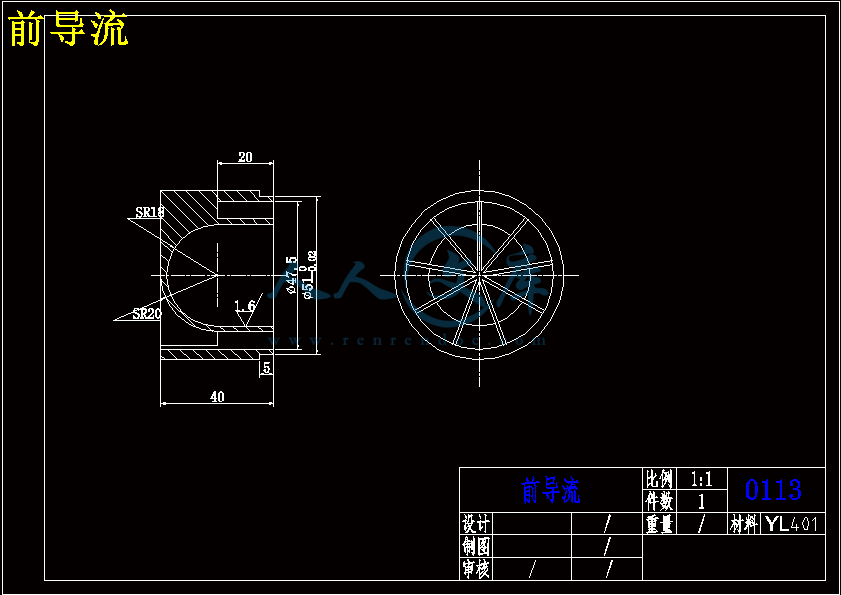
前导流.dwg

叶轮.dwg

后导流.dwg

气体涡轮流量计的设计与制造论文.doc

装配图.dwg

轴承.dwg

外文翻译--计算机辅助设计制造与应用.doc

目  录

1绪   论1

1.1 引言1

1.2 涡轮流量计的特点1

1.3气体涡轮流量计的应用场合3

1.4 发展前景6

2涡轮流量计的工作及结构原理7

2.1 TWLQ型气体涡轮流量计的工作原理7

2.2气体涡轮流量计的结构原理8

2.2.1 涡轮流量计的结构原理8

2.2.2 涡轮流量传感器的结构9

3气体涡轮流量计叶轮的改进21

3.1叶轮的叶型对加工的影响21

3.2叶轮叶型结构参数的确定22

4 导流器与传感器的改进26

4.1导流器的改进26

4.2传感器的改进29

4.2.1 传感器的分类29

4.2.2流体密度对传感器的影响30

5 TWLQ气体涡轮流量计中轴与轴承的改进34

5.1 涡轮轴的改进34

5.2 TWLQ气体涡轮流量计中轴承的结构改进35

6气体涡轮流量计的安装使用和维护38

6.1流量计的安装38

6.1.1传感器的安装38

6.1.2连接管道的安装39

6.2选用40

6.2.1传感器的选用40

6.2.2流量指示积算仪41

6.3使用注意事项41

6.4维护和故障处理42

结  论44

参考文献45

附录1:中英文翻译46

致  谢65

1绪   论

1.1 引言

   数千年前,人们为适应农业灌溉和水利的需要,就已开始关注着流量测量问题,古埃及出现了堰的雏形,而我国都江堰在那时也已经知道利用宝瓶口岩壁上所刻的“水则”,来观察水位,以进行控制[1]。

   到19世纪中叶,从节流式流量计开始,逐渐建立了近代流量计的理论基础。现代各类流量仪表也相继出现,如商用的水表,煤气表和文丘里管差压式流量计等。20世纪20-30年代,又出现了孔板和喷嘴差压式流量计,浮子流量计,融及时流量计以及宗法和稀释法等流量测量方法。20世纪50年代以后,随着电子技术,材料和加工技术的飞跃发展,以流程工业为先导的各工业部门和公用事业大量使用流量仪表,促使各种使用新颖的流量仪表相继问世和发展,如涡轮式,电磁式,超生式和涡街式流量计等。当代应用的流量仪表的主要品种,很多是这一阶段开发的。20世纪70年代后期又出现了科里奥利质量流量计。

1.2 涡轮流量计的特点

  流量计是一种速度式流量仪表。它是以动量守恒原理为基础的,流体冲击涡轮叶片,使涡轮旋转,涡轮的旋转速度随流量而变化,最后从涡轮的转数求出流量值。在二次仪表进行计数和显示,可反映出瞬时流量和累积流量(或称总量),也可以转换成标准信号进行远传。通常将涡轮流量计的感知流体留宿的涡轮及组合(包括前后导流架,轴承,客体即前置放大器)统称为涡轮流量传感器,而将涡轮转速检出后的信号处理,转换部分称为二次仪表或显示仪表。

   涡轮流量计之所以能够广泛地应用于石油工业领域。是因为涡轮流量计比其他形式的流量计,如容积式流量计有更突出的优点,如涡轮流量计具有流量范围宽、结构紧凑、简单、使用寿命长等优点,更重要的是,涡轮流量计能够经受严重的脉动而引起的超出流量上限的流量,以及流量计不会因为液体中所夹带的固体物从而导致管路系统的阻塞,一般小颗粒物质经过流量计时也不会引起损坏。但是,容积式流量计就不能容忍液体中夹带固体颗粒,这不仅会使流量计发生故障,更严重的是,一旦流量计卡死不转,将导致液体的阻塞而引起系统过压的现象,因此我们相信,涡轮流量计将会在石油工业领域,以及其他领域得到越来越广泛的应用,到如今占据全球领先位置。我国开展内近代流量测量技术方面的工作比较晚,20世纪60年代才开始有了国产流量计,发展到现在已经形成了一个相当规模从事流量测量技术和仪表研究开发和生产的产业,以逐步跻身世界领先水平。

   对于气体涡轮流量计的测量精度一般为0.25%R~1.5%R,对于液体涡轮流量计,它的测量精度一般为0.25%R~0.5%R,高精度型可达到0.15%R,特殊专用型为0.5% R~1% R。涡轮流量计的短期冲度型可达0.5%~0.2%。由于具有良好的重复性,因此其在贸易结算中被优先选用。 涡轮流量计的输出信号为脉冲频率,因此适用于总量及瞬时流量的计量与控制,且易于远传。信号的抗干扰能力也较强。但是涡轮流量计难以长期保持校准,需要定期校验。流体的密度,黏度等物理性质对仪表特性有较大影响,来流的速度分布和旋转来流对流量计的特性也有较大影响。

   智能化气体涡轮流量计是集流量,温度,压力检测功能于一体,并能进行温度,压力,压缩因子自动补偿的新一代流量计广泛应用于企业生产和家庭生活中。

   最贴近人民生活的家用燃气表和家用水表大多是采用涡轮结构的流量计,涡轮流量计是石油,化工,电力,冶金,工业锅炉等工业,行业的燃气计量和城市天然气,燃气调压站及燃气贸易计量的理想仪表。

   涡轮流量计,是速度式流量计中的主要种类,它采用多叶片的转子(涡轮)感受流体平均流速,从而推导出流量或总量的仪表。一般它由传感器和显示仪两部分组成,也可做成整体式。涡轮流量计和容积式流量计、科里奥利质量流量计称为流量计中三类重复性、精度最佳的产品,作为十大类型流量计之一,其产品已发展为多品种、多系列批量生产的规模。

气体涡轮流量计的优点[2]:

  (1)高精度,在所有流量计中,属于最精确的流量计;

  (2)重复性好;

1.3气体涡轮流量计的应用场合[3]

   涡轮流量计在以下一些测量对象上获得广泛应用:石油、有机液体、无机液、液化气、天然气和低温流体统在欧洲和美国,涡轮流量计在用量上是仅次于孔板流量计的天然计量仪表,仅荷兰在天然气管线上就采用了2600多台各种尺寸,压力从0.8~6.5MPa的气体涡轮流量计,它们已成为优良的天然气计量仪表。

   涡轮流量计是一种速度式仪表,它具有压力损失小,准确度高,起步流量低,抗震与抗脉动流性能好,范围度宽等容易维修的特点。

   气体涡轮流量计因其结构简单、线性好、精度高等特点而得以广泛应用。实际涡轮流量计在使用过程中受其结构参数及被测流体特性的影响,输入输出关系即特性曲线并非是理想直线,如图1-1所示(横坐标Q是体积流量;纵坐标K是流量系数)。   小流量区普遍存在着“驼峰”状非线性区,使涡轮流量计在小流量区测量误差较大。研究表明:涡轮流量计特性的影响因素很多,主要有被测流体介质粘性,涡轮流量计结构参数及来流速度分布等。对于来流速度分布的影响,实际应用中可控制流量计在安装管道中的位置(前后保持一定距离的直管道等措施),使来流速度分布相对均匀,因而本文引用理论计算与实际测量结果吻合较好的理论模型着重就流体介质粘性与流量计结构参数的综合影响进行探讨。

   天津第五机床厂生产的TWLQ型气体涡轮流量计,口径Ф50~Ф150mm,始动流量 3.0m3/h,流量范围10~150m3/h,介质温度-30℃~+60℃,工况压力小于1.6 Mpa ,准确度为1.5级,外形如下图1-2所示。图1-3 无锡求新公司生产的LWGQ气体涡轮传感器

   浙江苍南仪表有限公司LWQ型气体涡轮流量计其特点及结构参数如下:

特点:  (1)测量范围宽,下限流速低于0.5m/s,压力损失小,叶轮抗冲击能力强。  (2)具有较高的抗电磁干扰和抗振动能力,采用全密封隔离保护自润滑轴承, 性能可靠工作寿命长。  (3)采用先进的超低功耗单片微机技术,整机功能强,功耗低,性能优越。具有非线性精度补偿功能的智能流量显示器。

  (4)仪表系数可由按键在线设置,并可显示在LCD屏上,LCD屏直观清晰,可靠性高。  (5)采用EEPROM对累积流量、仪表系数进行掉电保护,保护时间大于10年。  (6)可在被测气体稳定的压力状态下进行压力补偿。   气体涡轮流量计是一种速度式仪表,它具有精度高,重复性好,结构简单,运动部件少,耐高压,测量范围宽,体积小,重量轻,压力损失小,流通能力大(同样口径可通过的流量大),维修方便等优点,且可适应高温,高压和低温流体的测量需要,用于封闭管道中测量低粘度气体的体积流量和总量。在城市天然气计量,输配气管网天然气计量,石油、化工、电力工业和民用等锅炉燃气计量,燃气调压站计量中得到了广泛的应用。

2涡轮流量计的工作及结构原理

2.1 TWLQ型气体涡轮流量计的工作原理[3]

   气体涡轮流量计是将涡轮置于被测流体中,当气体进入流量计时,在特殊结构整流器的作用下得到整流并加速,在一定流量范围内涡轮的角速度和流量成正比。利用电磁感应原理感应出与流体体积流量成正比的脉冲信号,该信号经前置放大器放大,整形后将得到实际流量,并显示在LCD屏上;如果同温度压力传感器检测到的信号一起输入智能流量积算仪进行运算处理,将得到标准状况下的流量,并显示于LCD屏上。如下图2-1所示

2.2气体涡轮流量计的结构原理

   叶轮式流量计是一种速度式流量计,主要有涡轮流量计、分流旋翼流量计、水表和叶轮风速计等。涡轮流量计时叶轮式流量计的主要品种,在国际上已有近半个世纪的工业应用历史,我国从60年代开始生产,已形成全系列化仪表。它利用置于流体中的叶轮的旋转角速度与流体流速成比例关系,通过测量叶轮的转速来反映通过管道的体积流量大小,是目前流量仪表中比较成熟的高精度仪表。涡轮流量计有涡轮流量传感器和流量显示仪表组成,可实现瞬时流量和累积流量的计量。传感器输出与流量成正比的脉冲频率信号,该信号通过传输线路远离传送仪表,便于累计和显示。此外传感器输出的脉冲频率信号可以单独与计算机配套使用,有计算机代替流量显示仪表实现密度或温度、压力补偿,显示质量流量或气体体积流量。本类仪表适用于流体总量的测量。如今,涡轮流量计已在石油、化工、科研、国防和计量等各部门中获得广泛应用。

2.2.1 涡轮流量计的结构原理[4]

   气体涡轮流量传感器的结构如下图2—2所示。它主要由仪表壳体1,前后导向架组件2和4,叶轮组件3和信号检测放大器6组成。当被测流体通过涡轮流量传感器时,流体通过导流器冲击涡轮叶片,由于涡轮的叶片与流体流向间有一倾角,流体的冲击力对涡轮产生转动力矩,使涡轮克服机械摩擦阻力矩和流动阻力矩而转动。实践表明,在一定的流量范围内,对于一定的流体介质粘度,涡轮的旋转角速度与通过涡轮的流量成正比。所以,可以通过测量涡轮的旋转角速度来测量流量。

  涡轮的旋转角速度一般都是通过安装在传感器壳体外面的信号检测放大器用磁电感应的原理来测量转换的。当涡轮转动时,涡轮上由YL401制成的螺旋形叶片依次接近和离开处于管壁外的磁电感应线圈,周期性地改变感应线圈磁回路的磁阻,是通过线圈的磁通量发生周期性的变化而产生与流量成正比的脉冲电信号。此脉冲信号经信号检测放大器放大整形后送至显示仪表(或计算机)显示流体流量或总量。

   在某一流量范围和一定粘度范围内,涡轮流量及输出的信号脉冲频率f与通过涡轮流量计的体积流量成正比。即:    本文对TWLQ型气体涡轮流量计的工作原理进行了详细的介绍,并着重对口径为Ф50系列的气体涡轮流量计内部结构进行了分析,其中包括了对流量计中涡轮轴,支撑轴承,叶轮,后导流器进行了结构的分析及重新设计。针对原产品在燃气市场中使用时存在的问题,其最大特点在于特性曲线与温度压力有关,气体压力损失在550-1400pa之间不等,不确定度可达1%-2%。针对这些不足之处,本文在产品的工作与结构原理中,通过特性分析了解到引起上述不足的因素,为后文对该产品的结构进行重新设计打下铺垫。其总结如下:

   1、叶轮的叶形是由机械中最难加工的复杂曲面组成的,要根据流体性质,流量范围,使用要求等设计,选择合适的叶片参数有利于流量计性能的更好发挥。

   2、在原有的结构基础之上重新选择密度更小的且摩擦系数更小的材料20Cr,使叶轮在转动过程中受的摩擦阻力矩降到最小。

本次结构改进后存在的问题:

1、改进后TWLQ系列气体涡轮流量计的内部零件,目前只是停留在理论的设计计

算阶段,还没有应用到实际的场合中去.

2、改进后的产品结构所选用的材料在性能上有很大的提高,但是不太符合经济

性要求。

3、下一步将通过与五机床技术人员的共同合作,进行该系列流量计内部零件的

实际加工并组装成产品,经过反复试验,投入到燃气市场中。

参考文献

[1]蔡武昌 应启嘎 编著 新型流量检测仪表 北京:化学工业出版社 2006年1月

[2]杨根生 林辉喻 编著 流量测量仪表     北京:机械工业出版社 1986年9月

[3]天津仪表集团有限公司 无锡求信集团有限公司 浙江苍南仪表有限公司等的涡轮流量计使用说明书  

[4]梁国伟 蔡武昌主编 流量测量技术及仪表 北京:机械工业出版社2002年6月

[5]方沂主编     数控机床编程与操作    北京:国防工业出版社  2006年8月

内容简介:
附录1:中英文翻译CAD CAM and Applications A Brief History of CAD Before we present the basics of CAD, it is appropriate to give a brief history. CAD is a product of the computer era. It originated from earl, computer graphic systems to the development of interactive computer graphics. Two such systems include the Sage Project at the Massachusetts Institute of Technology(MIT)and Sketchpad. The Sage Project was aimed at developing CRT displays and operating systems. Sketchpad was developed under the Sage Project. A CRT display and light pen input were used to interact with the system. This coincidentally hap note is that an X-Y plotter has the same basic structure as a NC drilling machine except that a pen is substituted for the tool on NC spindle. In the beginning, CAD systems were no more than graphics editor with some built-in design Symbols. The geometry available to the user was limited to lines, circular arcs, and the combination of the two. The development of free-form curves and surfaces, such as Coons patch, Beziers patch. and B-spline, enables a CAD system to be used for sophisticated curves and surface design. Three-dimensional CAD system allow a designer to move into the third Dimension. Because a three-dimensional model contains enough information for NC cutter-pathProgramming, the linkage between CAD and NC can be developed. So called turnkey CAD/CAM systems were developed based on this concept and became popular in the 1970s and 1980s.The 1970s marked the beginning of a new era in CAD-the invention of three-dimensional solid modeling. In the past, three-dimensional, wire-flame models represented an object only by its bounding edges. They are ambiguous in the sense that several interpretations might be possible for a single model. There is also no way to find the volumetric information of a model. Solid models contain complete information; therefore, not only can they be used to produce engineering drawing, but engineering analysis can be performed on the same model as well-Later. many commercial systems and research systems wecessary for solid modeling, many solid modelers now run on PCs, and the platform has become less of an issue. With the standard graphics user interface(GUI),CAD systems can be ported easily from one computer to another, Most major CAD systems are able to run on a variety of platforms. There is little difference between mainframe, workstation, and PC-based CAD systems.The Architecture of CAD A CAD system consists of three major parts: (1)Hardware computer and input/output (I/O) devices. (2)Operating system software. (3)Application software CAD package. Hardware is used to support the software functions. A wide range of hardware is used in CAD systems. The operating system software is the interface between the CAD application software and the hardware. It supervises the operation of the hardware and Provides basic functions such as creating and removing operation tasks, ontrolling the progress of tasks, allocating hardware resources among tasks, and providing access to software resources such as files, editors, compilers, and utility programs. It is important not only for CAD software, but also for non-CAD software. The application software is the heart of a CAD system. It consists of programs that do 2-D and 3-D modeling. Drafting and engineering analysis. The functionality of a CAD system is built into the application software. It is the application software that makes one CAD package different form another. Application software is usually operating-system-dependent. To transport a CAD system running in one operating system to another operating system is not as trivial as recompiling the software. Therefore, attention must be given to the operating system as well.Computer Aided Design Computer aided design gives the designer the ability to experiment with several possible Solutions. Usually some forms of design analysis calculations need to be done and many programs have been written for this task. The computer provides the designer with a powerful tool for analyzing proposed designs and for preparing formal drawings of the final design. Two-dimensional drawing is one area in which computer methods can offer significant, quantifiable cost advantages over traditional paper and pen methods, but a CAD system is not just an electronic drawing board. Computer drawing systems enable designers to produce fast accurate drawings and easily modify them. Draught productivity rises dramatically Two-Dimensional Drawings CAD makes possible multiview 2D drawings, with an endless possibility of views in a range of scales from microns to meters. It gives the mechanical designer the ability to magnify even the smallest of components to ascertain if the assembled components fit properly and even to design programs to identify automatically potential problems in CAD assembly. Parts with different characteristics such as movable or stationary, can be assigned different colors on the display. Parts can be dimensioned with automatic dimensioning changes, allowing for expedient engineering design changes.Three-Dimensional Drawings Designers have even more freedom with the advent of 3D modeling. They can create 3D parts and manipulate them in endless variations to achieve the desired results. Through finite element analysis (FEA),stresses can be applied to a computer model and the results graphically displayed, giving the designer quick feedback on any inherent problems in a design before the creation of a physical prototype. 3D models can be created in wire-flame, in surfaces or in solid form. In wire-frame, lines and arcs form edges that generate the model(Fig,8-la).The result is a 3D form that can be viewed from any location but is still only a skeletal form. Creating a surface stretches a skin over the skeleton(Fig,8-lb).Once this is done, the model can be rendered so that it appears more tangible. Surface models are commonly used in the creation of sheet metal developments that can be unfolded forManufacture. Solid models are the most complex level of modeling and while the programs to create them have been available for some time on large mainframe computers,it is only recently that microcomputers have reached a level of power that allows the running of the sophisticated algorithms needed to create solid models, The computer thinks the solid model is a solid mass so it can be ”drilled,” ”machined,” or ”welded” as if it were an actual physical part. It can be made out of any material and can take on that materials characteristics, thereby allowing calculations of mass to be made.CADs Benefits The benefits of computer use in drafting and design tasks are impressive: increased speed, greater accuracy, reduction of hardcopy storage space as well as better recall, enhanced communication capabilities, improved quality and easier modification. Speed A personal computer used in industry can perform a task at an average rate of 33 million operations per second; newer computers are even faster. This is an important feat when using it to calculate the amount of deflection of a component, when theoretical physical forces are applied to it, through finite element analysis(FEA)or when displaying an entire city plan on a monitor, both of which are time-consuming and calculation-intensive tasks. AutoCAD software can duplicate any geometry as many times as required and can also perform crosshatching and dimensioning automatically and equally as fast. Accuracy Because the computers data is stored in an electronic form, it can be sent to a variety of Locations. The first obvious location is the monitor. The computer can display the data on the screen in different forms such as graphics, easily converting the data into readable drawings. The data can also be sent to a plotter to produce the familiar paper drawing, via a direct link to a computer-aided manufacturing(CAM)machine or via telephone to anywhere around the globe. You no longer have to mail drawings, risking damage and loss; they can now be at their destination instantly via the telecommunications network. Quality The computer always retains the data in the form in which it was first created. It can repeat the same output of data continuously without regard to fatigue. Lines will always be crisp and clear, with uniform line weight, and text will always be legible. The computer doesnt alter its output quality because of a wild weekend or a late night watching the game. Modification The computer data is stored in a format that allows easy modification to any facet of a drawing and gives instant feedback to the user. When something is drawn once, it never has to be drawn again because the object in question can be duplicated, stretched, sized, and changed in many ways without having to be redrawn. Except for the initial cost to purchase a CAD workstation, CADs only disadvantage is a small one because it can be so easily overcome. Because the drawing is stored in an electronic format and not a paper format, it is possible to erase a drawing file easily. Thats why it is essential to train yourself in good CAD practices to avoid an accidental erasure. And-although an ounce of prevention truly is worth a pound of cure, there are even ways of unerasing files that are usually Successful if you follow the correct procedures. So relax ! Computer Aided Manufacturing When a design has frozen, manufacturing can begin. Computers have an important role to play in many aspects of production. Numerically controlled (NC) machine tools need a part program to define the components being made; computer techniques exist to assist, and in some cases virtually automate the generation of part programs. Modem shipbuilding fabricates structures from welded steel plates that are cut from a large steel sheet. Computer-controlled flame cutters are often used for this task and the computer is used to calculate the optimum layout of the components to minimize waste metal. Numerically controlled pipe-bending machines are able to operate directly from part programs generated by pipe-routing software. Printed circuit board assembly can also be improved by computer methods. Quality is maintained by computer-controlled automatic test equipment that diagnoses faults in a particular board and rejects defective boards from the assembly line. Computers are used extensively to plot the artwork used to etch printed circuit boards and also to produce part programs for NC drilling machines. One of the most important manufacturing function is stock and production control. If the original design is done on a computer, obtaining lists of material requirements is straightforward. Standard computer data processing methods are employed to organize the work flow and order components when required.Computer Aided Part ProgrammingPart programming software is used to ease programming for CNC machines when a complex part geometry requires calculation of a large number of tool positions. Part programming software is usually incorporated into a family of CAM (Computer Aided Manufacturing) software. Some CAM software is associated with CAD (Computer Aided Design) software into CAD/CAM stations .Then the CAM software can use the CAD files as a source of data, which speeds up the programming process. Part programming software is user-friendly, meaning the programmer does not have to know the computer programming language or its operating system. It uses screen menus to lead the user through the programming process. Data can be entered via the keyboard, the mouse, or the function Keys. Experienced programmers can use built-in macro capabilities and advanced techniques such as a family of parts to become even more productive.ilt-in software with communications capability.Good part programming software is capable of: (1)Establishing the machining parameters and tooling for a particular machine or job. (2)Defining the geometry and tool path. (3)Code generation-enabling the programmer to define what code is to be generated and how it is output to the machines. (4)Communication enabling the programmer to use standard communications protocols or create his or her own. NC Cutter-Path Verification Before a part is machined, the part program needs to be verified. The purposes of verification areorkpieceA dry cut can detect gross programming mistakes, but not the detailed geometric onesAnother approach is to actually machine a prototypeTypically, a prototype part is machined in wax, machining plastic, wood, foam, or some other soft materialThe actual geometry is then measured and compared with the design specificationBecause material property is critical in determining the cutting condition,this approach can verify only the geometryWhen a part program is generated using a CAD-based system, a graphic output of the cutter path may be produced by the softwareBy visual inspection,cutter-path abnormalities may be detected Figure 9-2 shows such an approach in a commercial CADCAM systemIn an advanced system,a solid model may be used to generate a realistic picture of the workpiece,tool and the finished part Real-time simulation of the cutting process can be displayed on screenHowever, most simulations are purely geometry-based, where the cutting condition is not consideredComputer Aided Process Planning Recent developments in computer-aided process planning have focused on eliminating the process planner from the entire planning functionComputer-aided process planning can reduce some of the decision making required during a planing processIt has the following advantages: (1)It can reduce the skill required of a planner (2)It can reduce process-planning time (3)It can reduce both process-planning and manufacturing costs Procrss planning is the critical bridge between design and manufacturing. Design informantion can be translated into manufacturing language only through process planning.Today,both computer-aided design(CAD)and manufacturing(CAM)have been implemented. Integrating, or bridging, these function requires automated process planning.Group Technology Any new component design needs its own unique identification number, usually the drawing nh drawing number is allocated by a coding system and each digit has meaning. If the code number is known, many of the component features can be deduced without reference to the drawing.Materials Requirement Planning Essentially this is the simple idea of combining the master production schedule with bills of materials to determine exactly the amount of raw materials components, etc., needed. This amount is compared with current stocks and used to calculate orders for new materials. The information is then combined with priority planning to ensure that correct orders go out in the correct sequence. Materials requirement planning(MRP)techniques have been available for some time, but with the advent of computers much more, accurate informationty in stock, unit of measure(feet of tubing, number of screws, etc.)minimum stock level, lead time of purchased or manufactured in-house.Robotics Robots are mechanical arms controlled by computer programs. Changing the program changes the set sequence of movements. The arms are articulated and there are two basic types of joints, revolute and prismatic. Revolute joints involve rotation about an axis and prismatic joints involve a slide of some kind, motion in a straight line (Fig.9-5).Each joint has its own servomotor, velocity and position transducer and is also called a degree of freedom. Different tools or end effectors can be attached to the end of the arm for different applications; for example, mechanical assembly, paint spraying and welding.Computer Integrated Manufacturing TodayS industry compete is in a truly international marketplace. Efficient transportation networks have created a ”world market” in which we participate on a daily basis. For anomers by allowing last-minute engineering-design changes without affecting shipping schedules or altering product quality.Most manufacturing companies look toward CAD,CAM and CIM to provide this flexibility in their manufacturing system. Today, the use of computers in manufacturing is common. Manufacturing system are being designed that not only process parts automatically, but also move the parts form machine to machine and sequence the ordering of operations in the system.Flexible Manufacturing Systems A flexibte manufacturing system, or FMS as they are more commonly known, is a reprogrammable manufacturing system capable of producing a variety of products automatically. Since Henry Ford first introduced and modernized the transfer line, we have been able to perform a variety of manufacturing operations automatically. However, altering these systems to accommodate even minor changes in the product has been quite taxing. Whole machines might have to be introduced to the system while other machined or components are modified or retired to accommodate small changes in a product. In todays competitive marketplace, it is necessary to accommodate customer changes or the customer will find so (1)Job shop type systems were capable of producing a variety of product, but at a high cost. (2)Transfer lines could produce large volumes of a product at a reasonable cost, but were limited to the production of one, two, or very few different parts. The advent of numerical control(NC)and robotics has provided us with reprogramming capabilities at the machine level with minimum setup time. NC machines and robots provide the basic physical building blocks for reprogrammable manufacturing systems. FMS Equipment In order to meet the requirements of the definition of an FMS, the basic processing in the system must be automated. Because automation must be programmable in order to accommodate a variety of product-processing requirements, easily alterable as well as versatile machines must perform the basic processing. For this reason, CNC turning centers(Fig.9-7),CNC machining centers, automated part inspection system, and robotic workstatio more tools(right-hand turning tools, left-hand turning tools, boring bars, drilling, and so on).The automatic tool changer and storage capabilities of NC machines make them natural choices for material-processing equipment. Parts must also be moved between processing stations automatically. Several different types of material-handling systems are employed to move these parts from station to station. The selection of the type of material-handling system is a function of several system featHresThe material-handling system, first, must be able to accommodate the load and bulk of the part and perhaps the part fixture. Large, heavy parts require large. powerful handling sy. A conveyor or automatic guided vehicle (AGV)system can be expanded to include miles of factory floor.计算机辅助设计制造与应用计算机辅助设计的简要历史 在我们讲述CAD的基本理论之前,先说说它的简史是比较合适的。CAD是计算机时代的产品。它从早期的计算机绘图系统发展到现在的交互式计算机图形学。两个这样的系统包括:麻省理工学院的Sage Project及Sketchpad。Sage Project旨在开发CRT显示器及操作系统。Sketchpad是在Sage Project下发展起来的。CRT显示和光笔输入用于与系统进行交互操作。CAD与初次出现的Nc和APT(自动编程工具)碰巧同时问世。后来,xY绘图仪作为计算机绘图的标准硬拷贝输出装置使用,一个有趣的现象是xY绘图仪与Nc钻床具有相同的基本结构,除了绘图笔被NC机床上的主轴刀具替代之外。 20世纪70年代,三维实体建模的发明标志着CAD一个新时代的开始。过去的三维线框模型仅用其边界来表达一个物体。这在某种意义上是含糊的,一个简单的模型可能有几种解释。同时也无法获得一个模型的体积信息。实体模型包含完整的信息,因此,它们不仅可用于生成工程图,而且也可在同一模型上完成工程分析。后来,开发了许多商业系统和研究系统。这些系统中相当多的是基于PADL和BUILD系统。尽管它们在表达上是强有力的,但仍然存在许多缺陷。例如,这种系统要有极强的计算能力和内存需求,非常规的物体建模方式以及标注公差能力的缺乏,这一切已阻碍了CAD的应用。直到20世纪80年代中期,实体建模开始介人设计环境。今天实体建模的应用如同绘图和线框模型应用一样普遍。在个人计算机上,CAD已走向大众化。这种发展使CAD应用面广并且很经济。CAD原本作为一种工具仅被航空和其它主要工业企业使用。诸如AutoCAD, VersaCAD, CADKEY等个人机CAD软件包的引入,使小型公司乃至个人可以拥有并使用CAD系统。到1988年为止已销售10万个以上的PC CAD软件包。今天,基于个人计算机的实体建模的Pc CAD易于获得,并且销售变得更为普及。由于微型计算机的迅速发展使得个人计算机能够承受实体模型需要的大量计算负荷,所以如今许多实体模型在PC机上运行,并且作为平台已不成为一个问题。随着标准图形用户界面的发展,CAD系统可以很容易地从一台计算机向另一台计算机传送,大多数CAD系统都能够在不同平台上运行。在大型计算机、工作站和基于个人计算机的CAD系统之间几乎没有区别。计算机辅助设计的结构 一个CAD系统包含三个主要部分: (1)硬件 计算机及输入输出装置。 (2)操作系统软件。 (3)应用软件 CAD软件包。 硬件主要用于支持软件功能。在CAD系统中使用着种类繁多的硬件。操作系统软件是CAD应用软件与硬件之间的
温馨提示:
1: 本站所有资源如无特殊说明,都需要本地电脑安装OFFICE2007和PDF阅读器。图纸软件为CAD,CAXA,PROE,UG,SolidWorks等.压缩文件请下载最新的WinRAR软件解压。
2: 本站的文档不包含任何第三方提供的附件图纸等,如果需要附件,请联系上传者。文件的所有权益归上传用户所有。
3.本站RAR压缩包中若带图纸,网页内容里面会有图纸预览,若没有图纸预览就没有图纸。
4. 未经权益所有人同意不得将文件中的内容挪作商业或盈利用途。
5. 人人文库网仅提供信息存储空间,仅对用户上传内容的表现方式做保护处理,对用户上传分享的文档内容本身不做任何修改或编辑,并不能对任何下载内容负责。
6. 下载文件中如有侵权或不适当内容,请与我们联系,我们立即纠正。
7. 本站不保证下载资源的准确性、安全性和完整性, 同时也不承担用户因使用这些下载资源对自己和他人造成任何形式的伤害或损失。
提示  人人文库网所有资源均是用户自行上传分享,仅供网友学习交流,未经上传用户书面授权,请勿作他用。
关于本文
本文标题:TWLQ型气体涡轮流量计的设计与制造【5张CAD图纸】【优秀】
链接地址:https://www.renrendoc.com/p-297788.html

官方联系方式

2:不支持迅雷下载,请使用浏览器下载   
3:不支持QQ浏览器下载,请用其他浏览器   
4:下载后的文档和图纸-无水印   
5:文档经过压缩,下载后原文更清晰   
关于我们 - 网站声明 - 网站地图 - 资源地图 - 友情链接 - 网站客服 - 联系我们

网站客服QQ:2881952447     

copyright@ 2020-2025  renrendoc.com 人人文库版权所有   联系电话:400-852-1180

备案号:蜀ICP备2022000484号-2       经营许可证: 川B2-20220663       公网安备川公网安备: 51019002004831号

本站为文档C2C交易模式,即用户上传的文档直接被用户下载,本站只是中间服务平台,本站所有文档下载所得的收益归上传人(含作者)所有。人人文库网仅提供信息存储空间,仅对用户上传内容的表现方式做保护处理,对上载内容本身不做任何修改或编辑。若文档所含内容侵犯了您的版权或隐私,请立即通知人人文库网,我们立即给予删除!