说明书.doc

拖拉机离合器壳体的落料、首次拉深复合模设计【优秀】【word+7张CAD图纸全套】【冲压复合模具类】【毕设】

收藏

压缩包内文档预览:(预览前20页/共40页)
预览图 预览图 预览图 预览图 预览图 预览图 预览图 预览图 预览图 预览图 预览图 预览图 预览图 预览图 预览图 预览图 预览图 预览图 预览图 预览图
编号:298683    类型:共享资源    大小:1.17MB    格式:RAR    上传时间:2014-07-24 上传人:QQ14****9609 IP属地:陕西
45
积分
关 键 词:
拖拉机 离合器壳体 首次 复合模具 设计 冲压模具
资源描述:

湖南12型拖拉机离合器壳体的落料、首次拉深复合模设计

离合器壳体落料、首次拉深复合模设计

拖拉机离合器壳体的落料、首次拉深复合模设计【优秀】【word+7张CAD图纸全套】【冲压复合模具类】【毕业设计】

【带任务书+开题报告+评阅评语表+答辩资格审查表+工作中期检查表+指导教师评阅表+实习日记+外文翻译+实习报告】【34页@正文17800字】【详情如下】【需要咨询购买全套设计请加QQ1459919609】

任务书.doc

外文翻译.doc

实习总结.doc

工作中期检查表.doc

开题报告.doc

指导教师审阅表.doc

正文.doc

答辩及最终成绩评定表.doc

答辩资格审查表.doc

翻译.doc

翻译英文.doc

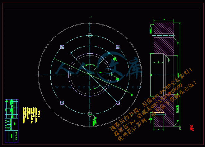
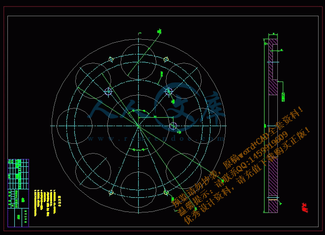
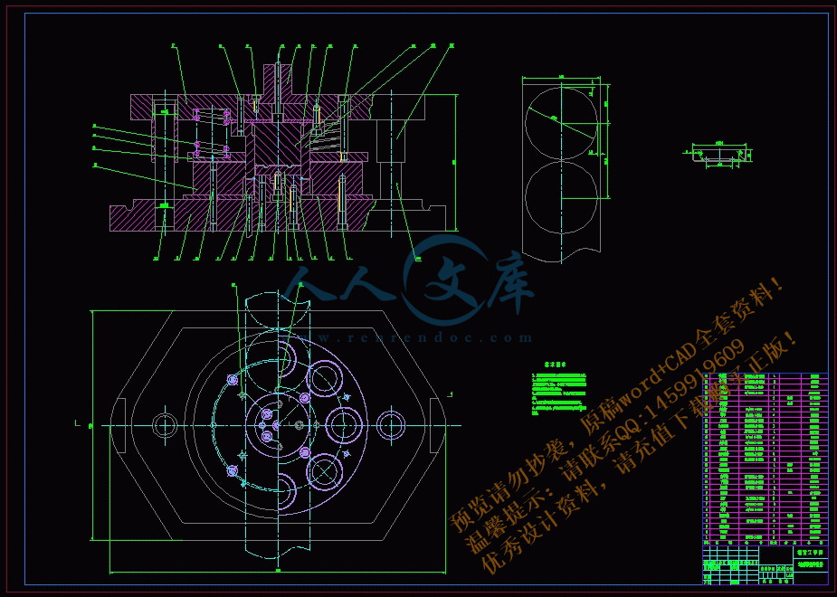
装配图及零件图合计7张图纸.dwg

评阅教师评阅表.doc

说明书.doc

任务书

课题名称湖南12型拖拉机离合器壳体落料、首次拉深复合模设计

内容及任务

设计图纸

模具总装图一张

全部模具零件图纸(其中至少有一张电脑绘图)

所有图纸折合成0号图不得少于3张。

设计说明书

1、资料数据充分,并标明数据出处。

2、计算过程详细、完全。

3、公式的字母含义应标明,有时还应标注公式的出处。

4、内容条理清楚,按步骤书写。

5、说明书要求用计算机打印。

6、设计说明书按要求格式独立撰写,不少于12000字。

自选一个重要模具零件编制加工工艺路线,进行相关的计算,并编制加工工艺卡和工序卡。

翻译一篇本专业外文文献(10000个以上印刷符号),并附译文。

拟达到的要求或技术指标1、保证规定的生产率和高质量的冲压件的同时,力求成本低、模具寿命长。

2、设计的冷冲模必须保证操作安全、方便。

3、冲模零件必须具有良好的工艺性,即制造装配容易、便于管理。

4、便于搬运、安装、紧固到冲床上并且方便、可靠。

5、保证模具强度前提下,注意外形美观,各部分比例协调。

进度安排起止日期工作内容备注

第2~5周(2.28~3.27)毕业调研及实习、搜集设计的相关资料

第6周(3.28~4.3)根据工件形状,确定工艺方案及模具结构型式

第7~8周(4.4~4.17)进行主要参数计算,画出模具装配结构草图

第9~10周(4.18~5.1)绘制模具总装配图

第11~12周(5.2~5.15)绘制模具各零件图

第13周(5.16~5.22)编制主要模具零件的加工工艺路线和工序卡

第14~15周(5.23~6.5)整理设计说明书、打印图纸资料,申请答辩

第16周(6.6~6.10)毕业答辩

主要参考资料1、《冷冲压工艺及模具设计》刘心治主编重庆大学出版社

2、《冲压工艺及模具设计》万战胜主编 铁道出版社

3、《冲模设计》 吉林人民出版社

4、《实用冲压技术》 机工出版社

5、《冷冲压及塑料成型工艺与模具设计资料》 机工出版社

6、《模具设计与制造简明手册》 冯炳尧等编 上海出版社

7、《冲压工艺模具设计实用技术》 郑家贤编 机械工业出版社

8、《实用板金冲压工艺图集》 梁炳文主编 机械工业出版社

9、《几何量公差与检测》甘永立主编 上海科学技术出版社

10、《机械制造专业英语》章跃主编 机械工业出版社

摘  要

本次的模具设计为离合器壳体落料、首次拉深复合模设计。离合器壳体才用的材料是20号钢,厚度3mm,该材料强度低,韧性、塑性和焊接性较好,用途非常广泛。适用于制造汽车、拖拉机及一般机械制造业中建造部分零件。如汽车上的手刹蹄片、杠杆轴、传动被动齿轮及拖拉机上的凸轮轴、悬挂均衡器轴、离合器壳体等。

首先对零件进行了工艺性分析,确定冲压所需的如落料、拉深,整形等一系列工序。其次经过计算分析确定工艺方案完成该模具的排样设计,凸、凹模工作部分的设计计算,还有模具结构和工艺零件设计,选择合适的模具材料和合理的加工工艺。在设计过程中,还利用CAD绘制了一套模具装配图和零件图。

关键词 :离合器壳体;落料;拉伸;复合模;设计

ABSTRACT

The mold design for the clutch housing blanking, drawing the first time, compound die design. Clutch housing material is used only 20 steel, the thickness of 3mm, the low material strength, toughness, ductility and good weldability, uses very extensive. For the manufacture of automobiles, tractors and general construction machinery manufacturing industry in some parts. If the car's hand brake shoe, lever shaft, transmission gears and tractor passive camshafts, suspension equalizer shaft, clutch housing and so on.

First of all parts of the process of analysis, to determine if the required blanking press, drawing, shaping and a series of processes. Second, after completion of the program calculation process to determine the layout of the mold design, convex and concave parts of the mold design and calculation work, as well as part design mold structure and process, select the appropriate mold material and reasonable process. In the design process, also used CAD drawing die assembly and part drawings

Key words Clutch housing;Blanking;Tensile;Compound Die;Design

目  录

前言……………………………………………………………………………………1

1  零件的工艺性 ……………………………………………………………………2

1.1  原始资料………………………………………………………………………2

  1.2  零件材料及其冲压工艺性分析……………………………………………2

  1.3  确定工艺方案和模具形式 …………………………………………… …4

2  主要工艺参数的计算 ……………………………………………………………5

  2.1  落料尺寸的计算……………………………………………………………5

  2.2  确定排样方案………………………………………………………………7

  2.3  计算拉深次数………………………………………………………………8

  2.4  拉深冲压力的计算…………………………………………………………9

  2.5  冲压设备的选择 …………………………………………………………11

3  模具设计…………………………………………………………………………12

  3.1  模具结构的设计 …………………………………………………………13

  3.2  模具的闭合高度 …………………………………………………………14

  3.3  模具工作部分尺寸及公差计算 …………………………………………14

4  冲模零件的设计…………………………………………………………………16

  4.1  落料凹模的设计 …………………………………………………………16

  4.2  凸凹模(落料凸模和拉深凹模)的设计 ………………………………19

  4.3  冲模的导向装置 …………………………………………………………19

  4.4  定位装置 …………………………………………………………………22

  4.5  卸料装置 …………………………………………………………………24

  4.6  推件装置的设计 …………………………………………………………25

  4.7  其它冲模零件设计 ………………………………………………………26

参考文献 ……………………………………………………………………………29

致谢 …………………………………………………………………………………30

附录 …………………………………………………………………………………31

前  言

冲压成形作为现代工业中一种十分重要的加工方法,用于生产各种板料零件,具有很多独特的优势,其成形件具有自重轻、刚度大、强度高、互换性好、成本低、生产过程便于实现机械自动化及生产效率高等优点,是一种其它加工方法所不能相比和不可代替的先进制造技术,在制造业中具有很强的竞争力,被广泛用于汽车、能源、机械、信息、航空、国防工业和日常生活生产之中。

在吸收了力学、数学、金属材料学、机械科学以及控制、计算机技术等方面的知识后,已经形成了冲压学科得成形基本理论。以冲压产品为龙头,以模具为中心,结合现代技术的应用,在产品的巨大市场需求刺激和推动下,冲压成形技术在国民经济发展,实现现代化和提高人民生活水平方面发挥着越来越重要的作用。

近几十年来,冲压技术有了飞速的发展,它不仅表现在许多新工艺与新技术在生产的广泛应用上,如:旋压成形、软模具成形、高能率成形等,更重要的是人们对冲压技术的认识与掌握的程度有了质的飞跃。现代冲压生产是一种大规模继续作业的制造方式,由于高新技术的参与与介入,冲压生产方式有初期的手工操作逐步进化为集成制造。生产过程逐步实现机械化,自动化,并且正在向智能化,集成化的方向发展。实现自动化冲压作业,体现安全、高效、节材等优点,已经是冲压生产的发展方向。

   冲压自动化生产的实现使冲压制造的概念有了本质的飞余跃,结合现代技术信息系统和现代化管理信息系统的成果,由这三个方面组合又形成现代冲压新的生产模式---计算机基层制造系统CIMS。把产品概念形成、设计、开发、生产、销售、售后服务全过程通过计算机等技术融成一体,将会给冲压制造业带来更好的经济效益,是现代冲压技术提高到一个新的高度。

1.零件的工艺性

1.1 原始资料

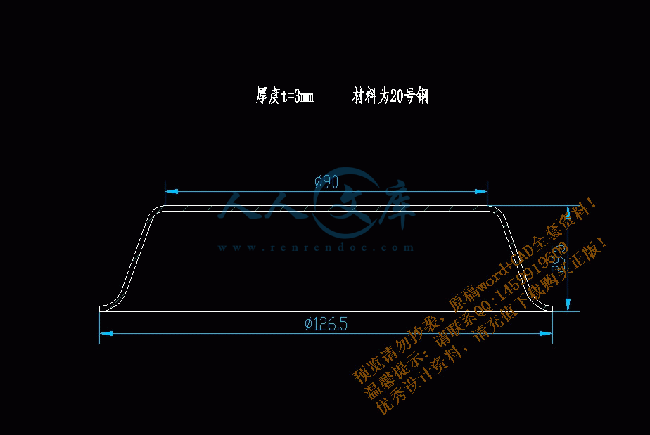
图1所示为离合器壳体零件,材料为20号钢,厚度为t=3mm,大批量生产。

参考文献

[1] 刘心志 《冷冲压工艺及模具设计》 重庆大学出版社

[2] 万战胜 《冲压工艺及模具设计》 铁道出版社

[3] 《冲模设计》 吉林人民出版社

[4] 《实用冲压技术》 机工出版社

[5] 《冷冲压及塑料成型工艺与模具设计资料》 机工出版社

[6] 冯炳尧《模具设计与制造简明手册》 上海出版社

[7] 郑家贤《冲压工艺模具设计实用技术》 机械工业出版社

[8] 梁炳文《实用板金冲压工艺图集》 机械工业出版社

内容简介:
任务书系: 机械工程系 专业: 材料成型及控制工程指导教师曾立平学生姓名黎勇课题名称湖南12型拖拉机离合器壳体落料、首次拉深复合模设计内容及任务设计图纸模具总装图一张全部模具零件图纸(其中至少有一张电脑绘图)所有图纸折合成0号图不得少于3张。设计说明书1、资料数据充分,并标明数据出处。2、计算过程详细、完全。3、公式的字母含义应标明,有时还应标注公式的出处。4、内容条理清楚,按步骤书写。5、说明书要求用计算机打印。6、设计说明书按要求格式独立撰写,不少于12000字。自选一个重要模具零件编制加工工艺路线,进行相关的计算,并编制加工工艺卡和工序卡。翻译一篇本专业外文文献(10000个以上印刷符号),并附译文。拟达到的要求或技术指标1、保证规定的生产率和高质量的冲压件的同时,力求成本低、模具寿命长。2、设计的冷冲模必须保证操作安全、方便。3、冲模零件必须具有良好的工艺性,即制造装配容易、便于管理。4、便于搬运、安装、紧固到冲床上并且方便、可靠。5、保证模具强度前提下,注意外形美观,各部分比例协调。进度安排起止日期工作内容备注第25周(2.283.27)毕业调研及实习、搜集设计的相关资料第6周(3.284.3)根据工件形状,确定工艺方案及模具结构型式第78周(4.44.17)进行主要参数计算,画出模具装配结构草图第910周(4.185.1)绘制模具总装配图第1112周(5.25.15)绘制模具各零件图第13周(5.165.22)编制主要模具零件的加工工艺路线和工序卡第1415周(5.236.5)整理设计说明书、打印图纸资料,申请答辩第16周(6.66.10)毕业答辩主要参考资料、冷冲压工艺及模具设计刘心治主编重庆大学出版社、冲压工艺及模具设计万战胜主编 铁道出版社、冲模设计 吉林人民出版社、实用冲压技术 机工出版社、冷冲压及塑料成型工艺与模具设计资料 机工出版社、模具设计与制造简明手册 冯炳尧等编 上海出版社7、冲压工艺模具设计实用技术郑家贤编机械工业出版社8、实用板金冲压工艺图集梁炳文主编机械工业出版社9、几何量公差与检测甘永立主编上海科学技术出版社10、机械制造专业英语章跃主编机械工业出版社教研室意见年 月 日系主管领导意见年 月 日Mold high speed milling processing technologyThe abstract Introduced the high speed milling in the mold processing application as well as the influence, and brief introduction high speed milling engine bed structure, control system and cutting tool. Has carried on the simple analysis to the high speed processing craft.Key word high speed milling; mold processingFirst, forewordIn the modern mold production, along with to models artistic and the function must obtain more and more high, models the internal structure to design more and more complex, the mold contour design day by day is also complex, the free curved surface accounts for the proportion to increase unceasingly, the corresponding mold structure also designs more and more complex. These all set a higher request to the mold processing technology, not only should guarantee the high manufacture precision and the surface quality, moreover must pursue the processing surface artistic. Along with is unceasingly thorough to the high speed processing engineering research, is processing the engine bed, the numerical control system, the cutting tool system, CAD/ especially Correlation technology and so on CAM software develops unceasingly under the impetus, high speed processes the technology more and more many to apply in the mold cavity processing and the manufacture.The numerical control high-speed cutting processing took in the mold manufacture a most important advanced manufacture technology, is the collection is highly effective, high quality, the low consumption in a body advanced manufacture technology. Is opposite in the traditional machining, its cutting speed, entered to the speed had the very big enhancement, moreover cut the mechanism not to be same. The high-speed cutting caused the machining to have the leap, its specific power metal excision rate enhanced 30%40%, the cutting force reduced 30%, the cutting tool working durability enhanced 70%, remained hotly large scale reduces in the work piece cutting, the low step shudder vanished nearly. Along with the cutting speed enhancement, unit time semifinished materials material removing rate increased, the cutting time reduced, the processing efficiency enhanced, thus reduced the product manufacture cycle, enhanced the product market competitive power. At the same time, the high speed processing small amount entered quickly causes the cutting force to reduce, the scrap high speed discharged reduced the work piece cutting force and the thermal load distorts, enhances the rigidity to be bad and the thin wall components machining possibility. Because cutting force reducing, the rotational speed enhancement causes the cutting system the operating frequency to be far away the engine bed the low step natural frequency, but the work piece surface roughness is most sensitive to the low step frequency, from this reduced the surface roughness. In mold high hard steel stock (HRC45HRC65) in the processing process, uses the high-speed cutting to be possible to substitute for the working procedure which the electrical finishing and rubs truncates polishes, thus has avoided the electrode manufacture and the time-consuming electrical finishing, large scale reduced fitters polishing with to throw the light quantity. Thin wall mold work piece more and more needs which regarding some markets in, the high speed milling also may smoothly complete, moreover in the high speed milling CNC processing center, a mold attire clamps may complete the multiplex step of processing.The high speed processing technology has had the huge influence to the mold processing craft, changed the traditional mold processing to use the annealing milling processing heat treatment to rub truncates or the electric spark machining manually polishes, polishes and so on the complex long technical process, even might use the high-speed cutting processing substitution original complete working procedure. The high speed processing technology besides may apply in the hard mold cavity direct processing (in particular half precision work and precision work), in EDM aspect and so on electrode processing, fast type manufacture also obtained the widespread application. The mass productions practice indicated that, the application high-speed cutting technology may save in the mold following processing 80% handwork to grind the time approximately, saves the processing cost expense nearly 30%, the mold face work precision may reach 1 m, the cutting tool cutting efficiency may enhance one time.Second, high speed milling processing engine bedThe high-speed cutting technology is one of machining technology main development directions, it along with foundation technology the and so on CNC technology, microelectronic technology, new material and new structure development but steps a higher stair. Because the mold processes particular as well as high speed processing technology own characteristic, (processed engine bed, numerical control system, cutting tool to the mold high speed processing related technology and the craft system and so on) proposed processed a higher request compared to the traditional mold.1.High stable engine bed strut partThe high-speed cutting engine bed lathe bed and so on supports the part to be supposed to have very well moves, the static rigidity, hot rigidity and best damping characteristic. The majority of engine beds all use high grade, the high rigidity and Gao Kangzhang the gray iron took the strut part material, some engine bed companies also increase the high damping characteristic in the foundation polymer concrete, by increases its vibration-proof and the thermostability, this not only may guarantee the engine bed precision is stable, also may prevent when cutting the cutting tool inspires trembles. Uses the enclosed lathe bed design, the overall casting lathe bed, the symmetrical lathe bed structure and has the densely covered stiffener and so on also enhances the engine bed stable important measure. Some engine bed companies research and development departments in design process, but also uses the modality analysis and the finite element structure computation and so on, optimized the structure, stably causes the engine bed strut part to be reliable.2.Engine bed main axleThe high speed engine bed main axle performance is the realization high-speed cutting processing important condition. The high-speed cutting engine bed main axle rotational speed scope is 10000100000m/Min, the main axle power is bigger than 15kW. Is not bigger than 0.005mm through the main axle compressed air of or axial play between the cooling system control hilt and the main axle. Also requests the main axle to have the fast vertical speed, to assign the performance which the position is fast stops (namely to have extremely high angle addition and subtraction speed), therefore the high speed main axle often uses the liquid static pressure bearing type, the air static pressure bearing type, the thermo-compression nitriding silicon (Si3N4) the ceramic bearing magnetism aerosol bearing type isostructuralism form. Lubricates uses technology and so on oil gas lubrication, splash lubrication. The main axle cools uses the main axle interior water cooling generally or air cooled.3.The engine bed actuates the systemIn order to satisfy the mold high speed processing the need, high speed processes the engine bed the actuation system to be supposed to have the following characteristic:(1) high entering for speed.The research indicated that, regarding the minor diameter cutting tool, enhances the rotational speed and each tooth enters for the quantity is advantageous in reduces the cutting tool attrition. At present commonly used entering for the speed range is 2030m/Min, like uses leads greatly the ball bearing guide screw transmission, enters may reach 60m/ for the speedMin; Uses the straight line electrical machinery then may enable to achieve 120m/ to the speedMin.(2) high acceleration.Has the good acceleration characteristic to the three dimensional complex curved surface silhouette high speed processing request actuation system, the request provides the driver which the high rapid advance or progress gives (to enter speed approximately 40m/ quicklyMin, the 3D outline processing speed is 10m/Min), can provide 0.4m/S2 to 10m/The s2 acceleration and reduces the speed.The engine bed manufacturer mostly uses the entire closed loop position servo-control slightly to lead, the great size, the high grade ball bearing guide screw or leads greatly many guide screws. Along with the electrical machinery technology development, the advanced straight line electric motor already was published, and the success applied in the CNC engine bed. The advanced straight line direct motor drive enable the CNC engine bed no longer to have the mass inertia, in advance, question and so on lag and vibration, sped up the servo speed of response, increased the servo-control precision and the engine bed processing precision.4.Numerical control systemThe advanced numerical control system is guaranteed the mold complex curved surface high speed processing quality and the efficiency key aspect, the mold high-speed cutting processing to the numerical control system basic request is: A. High speed numerical control return route (Digital control loop), including: 32 or above 64 bit parallel processors and 1.5Gb hard disk; Extremely short straight line electrical machinery sampling time. B. Speed and acceleration feed-forward control (Feed forward control); Digital actuation system crawling control (Jerk control).C. Advanced inserts makes up the method (to insert based on the NURBS transect makes up), by obtains the good surface quality, the precise size and the high geometry precision. D. Pretreatment (Look-ahead) function. The request has the large capacity cushion register, may read in advance and inspects many segments (for example the DMG engine bed to be possible to reach 500 segments, the Simens system may reach a 10002000 segment), in order to when is processed the superficial shape (curvature) changes may promptly adopt changes for measure and so on speed by avoids cutting and so on. E. The error compensatory function, including because the straight line electrical machinery, the main axle and so on gives off heat the hot error which causes to compensate, the quadrantal error compensates, the measurement system error compensates and so on the function. In addition, the mold high-speed cutting processing very is also high to the data transmission speed request. F. The traditional data connection, like the RS232 serial mouth transmission speed is 19.2kb, but many advanced processings centers have used the ether local area network (Ethernet) to carry on the data transmission, the speed may reach 200kb.5.Cooling lubricationThe high speed processing uses the belt coating the hard alloy tools, in high speed, the high temperature situation does not need the cutting compound, the cutting efficiency to be higher. This is because: The milling main axle high speed revolves, the cutting compound if achieved the cutting area, first must overcome the enormous centrifugal force; Even if it overcame the centrifugal force to enter the cutting area, also was possible as a result of the cutting area high temperature but to evaporate immediately, the cooling effect very small did not even have; At the same time the cutting compound can cause the cutting tool edge of a sword the temperature intense change, is easy to cause the crack the production, therefore must pick the oil used/Gas cooling lubrication dry type cutting way. This way may use the compressed gas rapidly the cutting which the cutting area produces, thus the massive cuttings hotly will carry off, at the same time might forms extremely thin microscopic protective film after the atomization lubricating oil in the cutting tool edge of a sword and the work piece surface, but effectively will lengthen the cutting tool life and enhances the components the surface quality.Third, high-speed cutting processing cutting toolThe cutting tool is in the high-speed cutting processing one of most active important factors, it is affecting the processing efficiency, the production cost and the product processing precision directly. The cutting tool must withstand load and so on high temperature, high pressure, friction, impact and vibration in the high speed processing process, the high-speed cutting cutting tool should have the good machine capability and the thermostability, namely has the good anti- impact, the wearability and resists heat the weary characteristic. The high-speed cutting processing cutting tool technological development speed is very quick, application many like diamonds (PCD), cubic boron nitride (CBN), ceramic cutting tool, coating hard alloy, (carbon) titanium nitrides hard alloy TIC (N) and so on.In the processing cast iron and in the alloy steel cutting tool, the hard alloy is the most commonly used cutting tool material. Hard alloy tools resistance to wear good, but the solidity ratio cube boron nitride and the ceramics are low. In order to enhance degree of hardness and the superficially attractive fineness, uses the cutting tool coating technology, the coating material for the titanium nitrides (TiN), the aluminium nitride titanium (TiALN) and so on. The coating technology causes the coating by the sole coating development for multilayered, the many kinds of coating material coating, has become one of enhancement high-speed cutting ability essential technical. The diameter in the 1040mm scope, also has the carbon titanium nitrides coating the hard alloy bit to be able to process the Luo river degree of hardness to be smaller than 42 materials, but the titanium nitrides aluminum coating cutting tool can process the Luo river degree of hardness is 42 even higher materials. When high-speed cutting steel products, the cutting tool material should select the hot rigidity and the fatigue strength high P kind of hard alloy, the coating hard alloy, the cubic boron nitride (CBN) and the CBN compound cutting tool material (WBN) and so on. The cutting cast iron, should select the fine grain K kind of hard alloy to carry on the rough machining, selects the compound nitrided silicon ceramics or the crystal combination cube boron nitride (PCNB) the compound cutting tool carries on the precision work. When precise processing non-ferrous metal or nonmetallic material, should select crystal combination diamond PCD or the CVD diamond coating cutting tool. When choice cutting parameter, in view of the circular shear blade and a ball milling cutter, should pay attention to the effective diameter the concept. The high speed milling cutting tool should press the balance design manufacture. The cutting tool front angle must be smaller than the conventional cutting tool front angle, the clearance angle is slightly big. The host vice- cutting edge attachment point should the cavetto or the lead angle, increases the vertex angle, prevents the knife point place hot attrition. Should enlarge nearby the knife point the cutting edge length and the cutting tool material volume, enhances the cutting tool rigidity. Is safe in the guarantee and satisfies the processing request under the condition, the cutting tool hangs extends as far as possible short, cutter body central toughness is friends with. The hilt must be sturdier than the cutting tool diameter, connects the handle to assume but actually the pyramidal, by increauses in the fine mill complex curved surface.Fourth, mold high speed processing craftThe high speed processing including take removes the remainder as the goal rough machining, the residual rough machining, as well as take gains the high grade processing surface and the slight structure as the goal half precision work, the precision work and the mirror surface processing and so on.1.Rough machiningThe mold rough machining essential target is pursues in the unit time material removing rate, and is half precision work preparation work piece geometry outline. In the high speed processing rough machining should adopt the craft plan is the high cutting speed, Gao Jin giving rate and the small cutting specifications combination. The contour processing way is one processing way which the multitudinous CAM software uses generally. Using is spiral contour and so on the Z axis contour two ways which are many, also is in processes the region only time to feed, in does not lift the knife in the situation to produce continuously the smooth cutting tool way, enters, draws back the knife way to use the circular arc to cut into, to cut. The spiral contour way characteristic is, has not waited the high level between the knife road migration, may avoid frequently lifting the knife, feeding to the components surface quality influence and mechanical device nonessential consuming. To is steep and the flat site processes separately, the computation suits contour and suits the use similar 3D bias the region, and may use the spiral way, in very little lifts the cutting tool way which the knife in the situation produces optimizes, obtains the better surface quality. In the high speed processing, certainly must adopt the circular arc to cut into, to cut the connection way, as well as the circular arc transition, avoids changing the cutting tool to enter suddenly for the direction, the prohibition use direct under knife connection way, avoids burying the cutting tool the work piece. When processes the mold cavity, should avoid the cutting tool vertical insertion work piece under, but should use inclines the knife way (commonly used angle of bank for 2030), best uses the screw type under knife by to reduce the cutting tool load. When processes the mold core, should under the knife then level cut into the work piece as far as possible first from the work piece. The cutting tool cuts into, cuts when the work piece should use as far as possible inclines the type (or round arc-type) cuts into, cuts, vertically avoids cutting into, cutting. Uses climbs up the type cutting to be possible to reduce the cutting heat, reduces the cutting tool stress and the work hardening degree, improves the processing quality.2.Half precision workThe mold half precision work essential target is causes the work piece outline shape smoothly, surface finish remainder even, this especially is important regarding the tool steel mold, because it will affect time the precision work cutting tool layer of cutting area change and cutting tool load change, thus influence cutting process stability and precision work surface quality.The rough machining is based on the volume model, the precision work then is based on the face mold. Before develops CAD/The CAM system to the components geometry description is not continual, after because has not described in front of the rough machining, the precision work processes the model the average information, therefore the rough machining surface surplus processing remainder distribution and the great surplus processing remainder is unknown. Therefore should fifty-fifty the precision work strategy carry on the optimization after to guarantee half precision work the work piece surface has the even surplus processing remainder. The optimized process includes: After the rough machining the outline computation, the great surplus processing remainder computation, the biggest permission processing remainder determination, is bigger than the biggest permission processing remainder the profile district (for example transition radius and so on scoop channel, corner is smaller than rough machining cutting tool radius region) as well as when half precision work the knife heart path computation to the surplus processing remainder and so on.The existing mold high speed processes CAD/The CAM software has the surplus processing remainder analysis function mostly, and can act according to the surplus processing remainder the size and the distribution situation uses the reasonable half precision work strategy. After like the MasterCAM software provided has tied the shape milling (Pencil milling) and the surplus milling (Rest milling) and so on the method eliminates the rough machining the surplus processing remainder big quoin by to guarantee the following working procedure even processing remainder.3.Precision workThe mold high speed precision work strategy is decided by the cutting tool and the work piece contact point, but the cutting tool and the work piece contact point but changes along with the processing surface curved surface slope and the cutting tool effective radius change. Regarding by the complex curved surface processing which many curved surface combination but becomes, should carry on the continuous treating as far as possible in a working procedure, but is not carries on the processing separately to each curved surface, by reduces lifts the knife, under the knife number of times. However, because processes the superficial slope change, if only defines the processing the side to eat the knife quantity (Step over), possibly creates on the slope different surface the actual step of distance non-uniformity, thus influence processing quality.In the ordinary circumstances, the precision work curved surface radius of curvature should be bigger than the cutting tool radius 1.5 times, by evades the no admittance to the direction suddenly transformation. In the mold high speed precision work, when each time cuts into, cuts the work piece, enters for the direction change should as far as possible use the circular arc or the curve switches over, avoids using the straight line to switch over, by maintains the cutting process the stability.Fifth, concluding remarkThe high-speed cutting technology is one of machining technology main development directions, at present mainly applies in the automobile industry and the mold profession, in the processing complex curved surface domain, work piece itself or the cutting tool system rigidity request high processing domain and so on, is the many kinds of advanced processings technology integration in particular, its is highly effective high grade, esteems for the people. It not only involves to the high speed processing craft, moreover also includes high speed processes the engine bed, the numerical control is systematic, the high-speed cutting cutting tool and CAD/CAM technology and so on. The mold high speed processing technology generally has applied at present in the developed country mold manufacturing industry, but still waited for in our countrys application scope and the application level the enhancement, because it had the tradition to process the incomparable superiority, still will be the next processing technology inevitable development direction.模具高速铣削加工技术摘 要 介绍了高速铣削在模具加工中的应用以及影响,并简要的介绍了高速铣削机床的结构、控制系统和刀具。对高速加工的工艺进行了简单的分析。关键词:高速铣削;模具加工一、 前言在现代模具生产中,随着对塑件的美观度及功能要求得越来越高,塑件内部结构设计得越来越复杂,模具的外形设计也日趋复杂,自由曲面所占比例不断增加,相应的模具结构也设计得越来越复杂。这些都对模具加工技术提出了更高要求,不仅应保证高的制造精度和表面质量,而且要追求加工表面的美观。随着对高速加工技术研究的不断深入,尤其在加工机床、数控系统、刀具系统、CAD/CAM软件等相关技术不断发展的推动下,高速加工技术已越来越多地应用于模具型腔的加工与制造中。数控高速切削加工作为模具制造中最为重要的一项先进制造技术,是集高效、优质、低耗于一身的先进制造技术。相对于传统的切削加工,其切削速度、进给速度有了很大的提高,而且切削机理也不相同。高速切削使切削加工发生了本质性的飞跃,其单位功率的金属切除率提高了30%40%,切削力降低了30%,刀具的切削寿命提高了70%,留于工件的切削热大幅度降低,低阶切削振动几乎消失。随着切削速度的提高,单位时间毛坯材料的去除率增加了,切削时间减少了,加工效率提高了,从而缩短了产品的制造周期,提高了产品的市场竞争力。同时,高速加工的小量快进使切削力减少了,切屑的高速排出减少了工件的切削力和热应力变形,提高了刚性差和薄壁零件切削加工的可能性。由于切削力的降低,转速的提高使切削系统的工作频率远离机床的低阶固有频率,而工件的表面粗糙度对低阶频率最为敏感,由此降低了表面粗糙度。在模具的高淬硬钢件(HRC45HRC65)的加工过程中,采用高速切削可以取代电加工和磨削抛光的工序,从而避免了电极的制造和费时的电加工,大幅度减少了钳工的打磨与抛光量。对于一些市场上越来越需要的薄壁模具工件,高速铣削也可顺利完成,而且在高速铣削CNC加工中心上,模具一次装夹可完成多工步加工。高速加工技术对模具加工工艺产生了巨大影响,改变了传统模具加工采用的“退火铣削加工热处理磨削”或“电火花加工手工打磨、抛光”等复杂冗长的工艺流程,甚至可用高速切削加工替代原来的全部工序。高速加工技术除可应用于淬硬模具型腔的直接加工(尤其是半精加工和精加工)外,在EDM电极加工、快速样件制造等方面也得到了广泛应用。大量生产实践表明,应用高速切削技术可节省模具后续加工中约80%的手工研磨时间,节约加工成本费用近30%,模具表面加工精度可达1 m,刀具切削效率可提高1倍。二、高速铣削加工机床高速切削技术是切削加工技术的主要发展方向之一,它随着CNC技术、微电子技术、新材料和新结构等基础技术的发展而迈上更高的台阶。由于模具加工的特殊性以及高速加工技术的自身特点,对模具高速加工的相关技术及工艺系统(加工机床、数控系统、刀具等)提出了比传统模具加工更高的要求。1. 高稳定性的机床支撑部件高速切削机床的床身等支撑部件应具有很好的动、静刚度,热刚度和最佳的阻尼特性。大部分机床都采用高质量、高刚性和高抗张性的灰铸铁作为支撑部件材料,有的机床公司还在底座中添加高阻尼特性的聚合物混凝土,以增加其抗振性和热稳定性,这不但可保证机床精度稳定,也可防止切削时刀具振颤。采用封闭式床身设计,整体铸造床身,对称床身结构并配有密布的加强筋等也是提高机床稳定性的重要措施。一些机床公司的研发部门在设计过程中,还采用模态分析和有限元结构计算等,优化了结构,使机床支撑部件更加稳定可靠。2. 机床主轴高速机床的主轴性能是实现高速切削加工的重要条件。高速切削机床主轴的转速范围为10000100000m/min,主轴功率大于15kW。通过主轴压缩空气或冷却系统控制刀柄和主轴间的轴向间隙不大于0.005mm。还要求主轴具有快速升速、在指定位置快速准停的性能(即具有极高的角加减速度),因此高速主轴常采用液体静压轴承式、空气静压轴承式、热压氮化硅(Si3N4)陶瓷轴承磁悬浮轴承式等结构形式。润滑多采用油气润滑、喷射润滑等技术。主轴冷却一般采用主轴内部水冷或气冷。3. 机床驱动系统为满足模具高速加工的需要,高速加工机床的驱动系统应具有下列特性:(1) 高的进给速度。研究表明,对于小直径刀具,提高转速和每齿进给量有利于降低刀具磨损。目前常用的进给速度范围为2030m/min,如采用大导程滚珠丝杠传动,进给速度可达60m/min;采用直线电机则可使进给速度达到120m/min。(2) 高的加速度。对三维复杂曲面廓形的高速加工要求驱动系统具有良好的加速度特性,要求提供高速进给的驱动器(快进速度约40m/min,3D轮廓加工速度为10m/min),能够提供0.4m/s2到10m/s2的加速度和减速度。机床制造商大多采用全闭环位置伺服控制的小导程、大尺寸、高质量的滚珠丝杠或大导程多头丝杠。随着电机技术的发展,先进的直线电动机已经问世,并成功应用于CNC机床。先进的直线电动机驱动使CNC机床不再有质量惯性、超前、滞后和振动等问题,加快了伺服响应速度,提高了伺服控制精度和机床加工精度。4. 数控系统先进的数控系统是保证模具复杂曲面高速加工质量和效率的关键因素,模具高速切削加工对数控系统的基本要求为: a. 高速的数字控制回路(Digital control loop),包括:32位或64位并行处理器及1.5Gb以上的硬盘;极短的直线电机采样时间。 b. 速度和加速度的前馈控制(Feed forward control);数字驱动系统的爬行控制(Jerk control)。 c. 先进的插补方法( 基于NURBS的样条插补),以获得良好的表面质量、精确的尺寸和高的几何精度。 d. 预处理(Look-ahead)功能。要求具有大容量缓冲寄存器,可预先阅读和检查多个程序段(如DMG机床可多达500个程序段,Simens系统可达10002000个程序段),以便在被加工表面形状(曲率)发生变化时可及时采取改变进给速度等措施以避免过切等。 e. 误差补偿功能,包括因直线电机、主轴等发热导致的热误差补偿
温馨提示:
1: 本站所有资源如无特殊说明,都需要本地电脑安装OFFICE2007和PDF阅读器。图纸软件为CAD,CAXA,PROE,UG,SolidWorks等.压缩文件请下载最新的WinRAR软件解压。
2: 本站的文档不包含任何第三方提供的附件图纸等,如果需要附件,请联系上传者。文件的所有权益归上传用户所有。
3.本站RAR压缩包中若带图纸,网页内容里面会有图纸预览,若没有图纸预览就没有图纸。
4. 未经权益所有人同意不得将文件中的内容挪作商业或盈利用途。
5. 人人文库网仅提供信息存储空间,仅对用户上传内容的表现方式做保护处理,对用户上传分享的文档内容本身不做任何修改或编辑,并不能对任何下载内容负责。
6. 下载文件中如有侵权或不适当内容,请与我们联系,我们立即纠正。
7. 本站不保证下载资源的准确性、安全性和完整性, 同时也不承担用户因使用这些下载资源对自己和他人造成任何形式的伤害或损失。
提示  人人文库网所有资源均是用户自行上传分享,仅供网友学习交流,未经上传用户书面授权,请勿作他用。
关于本文
本文标题:拖拉机离合器壳体的落料、首次拉深复合模设计【优秀】【word+7张CAD图纸全套】【冲压复合模具类】【毕设】
链接地址:https://www.renrendoc.com/p-298683.html

官方联系方式

2:不支持迅雷下载,请使用浏览器下载   
3:不支持QQ浏览器下载,请用其他浏览器   
4:下载后的文档和图纸-无水印   
5:文档经过压缩,下载后原文更清晰   
关于我们 - 网站声明 - 网站地图 - 资源地图 - 友情链接 - 网站客服 - 联系我们

网站客服QQ:2881952447     

copyright@ 2020-2025  renrendoc.com 人人文库版权所有   联系电话:400-852-1180

备案号:蜀ICP备2022000484号-2       经营许可证: 川B2-20220663       公网安备川公网安备: 51019002004831号

本站为文档C2C交易模式,即用户上传的文档直接被用户下载,本站只是中间服务平台,本站所有文档下载所得的收益归上传人(含作者)所有。人人文库网仅提供信息存储空间,仅对用户上传内容的表现方式做保护处理,对上载内容本身不做任何修改或编辑。若文档所含内容侵犯了您的版权或隐私,请立即通知人人文库网,我们立即给予删除!