鉴定意见.doc

行星齿轮减速箱运动仿真分析【7张CAD图纸】【优秀】

收藏

压缩包内文档预览:
预览图 预览图
编号:299552    类型:共享资源    大小:570.85KB    格式:RAR    上传时间:2014-07-27 上传人:上*** IP属地:江苏
45
积分
关 键 词:
行星 齿轮 减速箱 运动仿真 分析 cad图纸
资源描述:

行星齿轮减速箱运动仿真分析

26页10000字数+说明书+任务书+外文翻译+7张CAD图纸【详情如下】

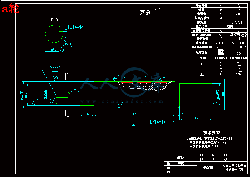
a轮.dwg

e轮.dwg

任务书.doc

前端盖.dwg

后端盖.dwg

外文翻译--轴和齿轮.doc

目录.docx

箱体1.dwg

行星齿轮减速箱运动仿真分析说明书.doc

装配图.dwg

论文封面.doc

评阅表.doc

转臂.dwg

鉴定意见.doc
 目录

1 绪论

 1.1行星减速器发展状况……………………………………………………………1

 1.2选题分析与设计内容……………………………………………………………3

2行星齿轮减速器装置设计

2.1基本参数要求与选择………………………………………………………………5

3行星齿轮设计计算

 3.1行星齿轮传动类型和传动简图的选择……………………………………………6

 3.2配齿计算……………………………………………………………………………6

 3.3初步计算齿轮的主要参数…………………………………………………………7

 3.4啮合参数计算………………………………………………………………………7

 3.5几何尺寸计算………………………………………………………………………10

 3.6装配条件计算………………………………………………………………………13

 3.7传动效率计算………………………………………………………………………13

 3.8机构设计……………………………………………………………………………14

 3.9行星齿轮强度验算…………………………………………………………………17

4 总结………………………………………………………………………………… 25

第一章    绪论

1.1行星减速器发展状况

由于国家采取了积极稳健的财政货币政策,固定资产投资力度加大,特别是基础建设的投资,使冶金、电力、水泥、建筑、建材、能源等加快了发展,因此,对减速机的需求也逐步扩大。随着国家对机械制造业的重视,重大装备国产化进程的加快以及城市化改造进程的加快,减速机行业仍将保持快速发展态势,尤其是齿轮减速机的增长将会大幅度提高,这与进口设备大多配套采用齿轮减速机有关。因此,业内专家希望企业抓紧开发制造齿轮减速机,尤其是大、中、小功率硬齿面减速机,以满足市场的需求。

国内外动力齿轮传动正沿着小型化、高速化、标准化、小振动、低噪声的方向发展。行星齿轮传动的发展和少齿差零齿差内齿轮副的应用,是当代齿轮的一大特征,是齿轮传动小型化的一个典型的标志。行星传动把传统的定轴传动改为动轴传动,采用了功率分流并合理应用内啮合及均载装置,具有重量轻,体积小,承载高等优点,因此,行星传动技术的应用日渐广泛。

   20世纪末的20多年,世界齿轮技术有了很大的发展,铲平发展的总趋势是小型化,高速化,低噪声,高可靠度。技术发展中最引人注目的是应吃面技术,功率分支技术和模块化设计技术。

   硬面齿轮技术到20世纪80年代在国外日趋成熟。采用优质合金钢锻件神探淬火磨齿的硬齿面齿轮,精度不低于IS01328-1975的6级,综合承载能力为中硬齿面调质齿轮的4倍,为软齿面齿轮的5-6倍。一个中等规格的硬齿面齿轮减速器的重量仅为软吃面齿轮减速器的1/3左右

   功率分支技术主要指行星及大功率齿轮箱的功率双份及多分支装置,如中心传动的水泥磨主减速器,其核心技术是均载。

   模块化设计技术队通用和标准减速器旨在追求高性能和满足用户多样化大覆盖面需求的同时,尽量减少零部件及毛坯的品种规格,以便于组织生产,使零部件产生形成批量,降低成本,取得规模效益。

   其他技术的发展还表现在理论研究(如强度计算,修形技术,现代设计方法的应用,新齿形,新结构的应用等)更完善,更接近实际;普通采用各种优质合金钢锻件;材料和热处理质量控制水平的提高;结构设计更合理;加工精度普遍提高到ISO的4-6级;轴承质量和寿命的提高;润滑油质量的提高;加工装备和检测手段的提高等方面。

   这些技术的应用和日趋成熟,使齿轮产品的性能价格比大大提高,产品越来越完美。如非常粗略地估计一下,输出100N m转矩的齿轮装置,如果在1950年时重10kg,到80年代就可做到仅为1kg。

   20世纪70年代至90年代初,我国的高速齿轮技术经历了测绘仿制,技术引进到独立设计制造3个阶段。现在我国的设计制造能力基本可满足国内生产需要,设计制造的最高参数:最大功率44MW,最高线速度168m/s,最高转速67000r/min。

   我国的低速重载齿轮技术,特别是硬齿面齿轮技术也经历了测绘仿制等阶段,从无到有逐步发展起来。除了摸索掌握制造技术外,在20世纪80年代末至90年代初步推广硬齿面技术过程中,我们还做了解决“断轴”,“选用”等一系列有意义的工作。在20世纪70-80年代一直认为是国内重齿轮两大难题的“水泥磨减速器”和“轧钢机械减速器”可以说已完全解决。

   20世界80年代至90年代初,我国相继制定了一批减速器标准,如ZBJ19004—88《圆柱齿轮减速器》,ZBJ19026—90《运输机械用减速器》和YB/T050—93《冶金设备用YNK齿轮减速器》等几个硬齿面减速器标准,我国有自己只是产权的标准,如YB/T079—95《三环减速器》。按这些标准生产的许多产品的主要技术指标均可达到或接近国外同类产品的水平,其中YNK减速器较完整地吸取了德国FLENDER公司同类产品的特点,并结合国情做了血多改进与创新。

   世界上一些工业发达国家,如日本,德国,英国,美国和俄罗斯等,对行星齿轮传动的应用,生产和研究都十分重视,在结构优化,传动性能,传动效率,转矩和速度等方面均处于领先地位,并出现一些新型的行星齿轮传动技术,如封闭行星齿轮传动,行星齿轮变速传动和微型行星齿轮传动等早已在现代化的机械传动设备中获得了成功的应用。

   行星齿轮传动与普通定州齿轮传动相比较,具有质量小,体积小,传动比大,承载能力大以及传动平稳和传动效率高等优点,这些已经被我过越来越多的机械工程技术人员所了解和重视。由于在各种类型的行星齿轮传动种均有效地利用了功率分流性和输入,输出地同轴性以及合理的采用了内啮合,才使得其具有了上述的许多独特的优点。行星齿轮传动不仅适用于高速,大功率而且可用于低速,大转矩的机械传动装置上。它可以用作减速,增速和变速传动,运动的合成和分解,以及其特殊的应用中:这些功用对于现代机械传动发展有着重要意义。因此,行星齿轮传动在起重运输,工程机械,冶金矿山,石油化工,建筑机械,轻工纺织,医疗器械,仪器仪表,汽车,船舶,兵和航空航天等工业部门获得了广泛的应用。

  本设计以本设计基于Solid Works便于交互及强大的二维、三维绘图功能。先确定总体思路、设计总体布局,然后设置零部件,最后完成一个完整的设计。利用Solid Works模块实现装配中零部件的装配、运动学仿真等功能。

   行星齿轮减速器的体积、重量及其承载能力主要取决于传动参数的选择,设计问题一般是在给定传动比和输入转矩的情况下,确定各轮的齿数,模数和齿宽等参数。其中优化设计采用Solid Works自带的模块,模拟真实环境中的工作状况进行运动仿真,对元件进行运动分析。

   减速器作为独立的驱动元部件,由于应用范围极广,其产品必须按系列化进行设计,以便于制造和满足不同行业的选用要求。针对其输人功率和传动比的不同组合,可获得相应的减速器系列。在以往的人工设计过程中,在图纸上尽管能实现同一机座不同规格的部分系列表示,但其图形受到极大限制。采用Solid Works工具来实现这一过程,不仅能完善上述工作,,方便设计操作,而且使系列产品的技术数据库,图形库的建立、查询成为可能,使设计速度加快。在设计过程中,我利用互联网对本课题的各设计步骤与任务进行了详细了解。采用计算机辅助设计的技术,利用Solid Works参数化建模。

  在设计计算方面:分析行星齿轮机构传动方案;并通过计算分析,确定行星轮系齿轮的齿数、模数和轴、行星架的各项参数,校核齿轮的接触和弯曲强度;完成内外啮合齿轮、轴、行星架的设计计算;在整机设计开发背景下,结合运动参数完成建模。

 在工程仿真分析方面:本论文利用三维软件Solid Works对行星轮减速器进行三维建模,并完成与整机的装配。2.1基本参数要求与选择

      行星齿轮传动的类型很多,其分类方法也不少。在库氏的分类方法中,行星齿轮传动的基本代号为:Z——中心轮,X——转臂,V——输出轴(现说明:在库氏原著作中,K—中心轮,H—转臂)。根据其基本构件的配置情况,可将行星齿轮传动分为2Z-X、3Z和Z-X-V三种基本传动类型;其他的结构型式的行星齿轮传动大都是它们的演化型式或组合型式。

  设计行星齿轮减速器,已知该行星传动的输入功率P1=22KW,输入转速n1=1500r/min,传动比ip=134,允许的传动比偏差△ip=0.01,短期间断的工作方式,每天工作16h,要求使用寿命8年;且要求该行星齿轮传动结构紧凑、外廓尺寸较小和传动功率较高。

参考文献

[1] 璞良贵,纪名刚主编.机械设计.第八版.北京:高等教育出版社,2005

[2] 王昆主编.机械设计课程设计.武汉:华中理工大学出版社,1922

[3] 卢颂峰、王大康主编.机械设计课程设计.北京:北京工业大学出版社,1993

[4] 吴宗泽、罗圣国主编.机械设计课程设计手册.北京:高等教育出版社,1992

[5] 孙桓,陈作模主编.机械原理.第六版.北京:高等教育出版社,2002

[6] 成大先主编.机械设计手册.北京:化学工业出版社,2004

[7] 饶振纲编著.行星齿轮传动设计.北京:化学工业出版社,2003

[8] 饶振纲.行星齿轮变速箱的设计与研究.传动设计,1999,(2)

[9] 中华人民共和国国家标准.GB/T272-93.滚动轴承的代号.北京:中国标准出版社

内容简介:
湘 潭 大 学毕业论文(设计)任务书论文(设计)题目: 行星减速箱运动仿真分析 学号: 2010962929 姓名: 谭绍元 专业: 机械设计制造及自动化(兴) 指导教师: 刘柏希 系主任: 刘柏希 一、主要内容及基本要求 本设计的主要内容为: 1根据给定工况,设计行星齿轮减速器主体结构; 2. 按照分解后的结构,在ProE或UG环境下进行关键部件的建模; 3. 在ProE或UG环境下对行星减速器进行装配,并对装配后的减速器整机进行运动学仿真分析。 本设计的基本要求如下: 1掌握减速器的关键设计步骤; 2掌握关键部件的三维建模及装配; 3掌握整机运动学分析方法。 二、重点研究的问题 本设计的重点研究问题有两个: 1减速器关键部件特别是具有复杂形状零部件的三维建模。 2减速器的整机运动学仿真分析。 三、进度安排序号各阶段完成的内容完成时间1查阅相关资料第1周2掌握减速器结构和关键设计步骤第23周3关键零部件的建模及整机装配第49周4整机运动学仿真第911周5翻译相关英文资料一份3000字左右第12周6撰写毕业论文(设计)说明书第13周78四、主要参考文献1 璞良贵,纪名刚主编.机械设计.第八版.北京:高等教育出版社,2005 2 王昆主编.机械设计课程设计.武汉:华中理工大学出版社,19223 卢颂峰、王大康主编.机械设计课程设计.北京:北京工业大学出版社,19934 吴宗泽、罗圣国主编.机械设计课程设计手册.北京:高等教育出版社,19925 孙桓,陈作模主编.机械原理.第六版.北京:高等教育出版社,2002 6 成大先主编.机械设计手册.北京:化学工业出版社,2004 7 饶振纲编著.行星齿轮传动设计.北京:化学工业出版社,20038 饶振纲.行星齿轮变速箱的设计与研究.传动设计,1999,(2)9 中华人民共和国国家标准.GB/T272-93.滚动轴承的代号.北京:中国标准出版社GEAR AND SHAFT INTRODUCTIONSi TuzhongAbstract: The important position of the wheel gear and shaft can falter in traditional machine and modern machines.The wheel gear and shafts mainly install the direction that delivers the dint at the principal axis box.The passing to process to make them can is divided into many model numbers, useding for many situations respectively.So we must be the multilayers to the understanding of the wheel gear and shaft in many ways .Key words: Wheel gear;ShaftIn the force analysis of spur gears, the forces are assumed to act in a single plane. We shall study gears in which the forces have three dimensions. The reason for this, in the case of helical gears, is that the teeth are not parallel to the axis of rotation. And in the case of bevel gears, the rotational axes are not parallel to each other. There are also other reasons, as we shall learn.Helical gears are used to transmit motion between parallel shafts. The helix angle is the same on each gear, but one gear must have a right-hand helix and the other a left-hand helix. The shape of the tooth is an involute helicoid. If a piece of paper cut in the shape of a parallelogram is wrapped around a cylinder, the angular edge of the paper becomes a helix. If we unwind this paper, each point on the angular edge generates an involute curve. The surface obtained when every point on the edge generates an involute is called an involute helicoid.The initial contact of spur-gear teeth is a line extending all the way across the face of the tooth. The initial contact of helical gear teeth is a point, which changes into a line as the teeth come into more engagement. In spur gears the line of contact is parallel to the axis of the rotation; in helical gears, the line is diagonal across the face of the tooth. It is this gradual of the teeth and the smooth transfer of load from one tooth to another, which give helical gears the ability to transmit heavy loads at high speeds. Helical gears subject the shaft bearings to both radial and thrust loads. When the thrust loads become high or are objectionable for other reasons, it may be desirable to use double helical gears. A double helical gear (herringbone) is equivalent to two helical gears of opposite hand, mounted side by side on the same shaft. They develop opposite thrust reactions and thus cancel out the thrust load. When two or more single helical gears are mounted on the same shaft, the hand of the gears should be selected so as to produce the minimum thrust load.Crossed-helical, or spiral, gears are those in which the shaft centerlines are neither parallel nor intersecting. The teeth of crossed-helical fears have point contact with each other, which changes to line contact as the gears wear in. For this reason they will carry out very small loads and are mainly for instrumental applications, and are definitely not recommended for use in the transmission of power. There is on difference between a crossed helical gear and a helical gear until they are mounted in mesh with each other. They are manufactured in the same way. A pair of meshed crossed helical gears usually have the same hand; that is ,a right-hand driver goes with a right-hand driven. In the design of crossed-helical gears, the minimum sliding velocity is obtained when the helix angle are equal. However, when the helix angle are not equal, the gear with the larger helix angle should be used as the driver if both gears have the same hand. Worm gears are similar to crossed helical gears. The pinion or worm has a small number of teeth, usually one to four, and since they completely wrap around the pitch cylinder they are called threads. Its mating gear is called a worm gear, which is not a true helical gear. A worm and worm gear are used to provide a high angular-velocity reduction between nonintersecting shafts which are usually at right angle. The worm gear is not a helical gear because its face is made concave to fit the curvature of the worm in order to provide line contact instead of point contact. However, a disadvantage of worm gearing is the high sliding velocities across the teeth, the same as with crossed helical gears.Worm gearing are either single or double enveloping. A single-enveloping gearing is one in which the gear wraps around or partially encloses the worm. A gearing in which each element partially encloses the other is, of course, a double-enveloping worm gearing. The important difference between the two is that area contact exists between the teeth of double-enveloping gears while only line contact between those of single-enveloping gears. The worm and worm gear of a set have the same hand of helix as for crossed helical gears, but the helix angles are usually quite different. The helix angle on the worm is generally quite large, and that on the gear very small. Because of this, it is usual to specify the lead angle on the worm, which is the complement of the worm helix angle, and the helix angle on the gear; the two angles are equal for a 90-deg. Shaft angle.When gears are to be used to transmit motion between intersecting shaft, some of bevel gear is required. Although bevel gear are usually made for a shaft angle of 90 deg. They may be produced for almost any shaft angle. The teeth may be cast, milled, or generated. Only the generated teeth may be classed as accurate. In a typical bevel gear mounting, one of the gear is often mounted outboard of the bearing. This means that shaft deflection can be more pronounced and have a greater effect on the contact of teeth. Another difficulty, which occurs in predicting the stress in bevel-gear teeth, is the fact the teeth are tapered. Straight bevel gears are easy to design and simple to manufacture and give very good results in service if they are mounted accurately and positively. As in the case of squr gears, however, they become noisy at higher values of the pitch-line velocity. In these cases it is often good design practice to go to the spiral bevel gear, which is the bevel counterpart of the helical gear. As in the case of helical gears, spiral bevel gears give a much smoother tooth action than straight bevel gears, and hence are useful where high speed are encountered. It is frequently desirable, as in the case of automotive differential applications, to have gearing similar to bevel gears but with the shaft offset. Such gears are called hypoid gears because their pitch surfaces are hyperboloids of revolution. The tooth action between such gears is a combination of rolling and sliding along a straight line and has much in common with that of worm gears.A shaft is a rotating or stationary member, usually of circular cross section, having mounted upon it such elementsas gears, pulleys, flywheels, cranks, sprockets, and other power-transmission elements. Shaft may be subjected to bending, tension, compression, or torsional loads, acting singly or in combination with one another. When they are combined, one may expect to find both static and fatigue strength to be important design considerations, since a single shaft may be subjected to static stresses, completely reversed, and repeated stresses, all acting at the same time.The word “shaft” covers numerous variations, such as axles and spindles. Anaxle is a shaft, wither stationary or rotating, nor subjected to torsion load. A shirt rotating shaft is often called a spindle.When either the lateral or the torsional deflection of a shaft must be held to close limits, the shaft must be sized on the basis of deflection before analyzing the stresses. The reason for this is that, if the shaft is made stiff enough so that the deflection is not too large, it is probable that the resulting stresses will be safe. But by no means should the designer assume that they are safe; it is almost always necessary to calculate them so that he knows they are within acceptable limits. Whenever possible, the power-transmission elements, such as gears or pullets, should be located close to the supporting bearings, This reduces the bending moment, and hence the deflection and bending stress.Although the von Mises-Hencky-Goodman method is difficult to use in design of shaft, it probably comes closest to predicting actual failure. Thus it is a good way of checking a shaft that has already been designed or of discovering why a particular shaft has failed in service. Furthermore, there are a considerable number of shaft-design problems in which the dimension are pretty well limited by other considerations, such as rigidity, and it is only necessary for the designer to discover something about the fillet sizes, heat-treatment, and surface finish and whether or not shot peening is necessary in order to achieve the required life and reliability.Because of the similarity of their functions, clutches and brakes are treated together. In a simplified dynamic representation of a friction clutch, or brake, two inertias I1 and I2 traveling at the respective angular velocities W1 and W2, one of which may be zero in the case of brake, are to be brought to the same speed by engaging the clutch or brake. Slippage occurs because the two elements are running at different speeds and energy is dissipated during actuation, resulting in a temperature rise. In analyzing the performance of these devices we shall be interested in the actuating force, the torque transmitted, the energy loss and the temperature rise. The torque transmitted is related to the actuating force, the coefficient of friction, and the geometry of the clutch or brake. This is problem in static, which will have to be studied separately for eath geometric configuration. However, temperature rise is related to energy loss and can be studied without regard to the type of brake or clutch because the geometry of interest is the heat-dissipating surfaces. The various types of clutches and brakes may be classified as fllows: 1. Rim type with internally expanding shoes2. Rim type with externally contracting shoes3. Band type4. Disk or axial type5. Cone type6. Miscellaneous typeThe analysis of all type of friction clutches and brakes use the same general procedure. The following step are necessary: 1. Assume or determine the distribution of pressure on the frictional surfaces.2. Find a relation between the maximum pressure and the pressure at any point3. Apply the condition of statical equilibrium to find (a) the actuating force, (b) the torque, and (c) the support reactions.Miscellaneous clutches include several types, such as the positive-contact clutches, overload-release clutches, overrunning clutches, magnetic fluid clutches, and others.A positive-contact clutch consists of a shift lever and two jaws. The greatest differences between the various types of positive clutches are concerned with the design of the jaws. To provide a longer period of time for shift action during engagement, the jaws may be ratchet-shaped, or gear-tooth-shaped. Sometimes a great many teeth or jaws are used, and they may be cut either circumferentially, so that they engage by cylindrical mating, or on the faces of the mating elements.Although positive clutches are not used to the extent of the frictional-contact type, they do have important applications where synchronous operation is required.Devices such as linear drives or motor-operated screw drivers must run to definite limit and then come to a stop. An overload-release type of clutch is required for these applications. These clutches are usually spring-loaded so as to release at a predetermined toque. The clicking sound which is heard when the overload point is reached is considered to be a desirable signal.An overrunning clutch or coupling permits the driven member of a machine to “freewheel” or “overrun” because the driver is stopped or because another source of power increase the speed of the driven. This type of clutch usually uses rollers or balls mounted between an outer sleeve and an inner member having flats machined around the periphery. Driving action is obtained by wedging the rollers between the sleeve and the flats. The clutch is therefore equivalent to a pawl and ratchet with an infinite number of teeth. Magnetic fluid clutch or brake is a relatively new development which has two parallel magnetic plates. Between these plates is a lubricated magnetic powder mixture. An electromagnetic coil is inserted somewhere in the magnetic circuit. By varying the excitation to this coil, the shearing strength of the magnetic fluid mixture may be accurately controlled. Thus any condition from a full slip to a frozen lockup may be obtained.齿轮和轴的介绍司徒忠摘要:在传统机械和现代机械中齿轮和轴的重要地位是不可动摇的。齿轮和轴主要安装在主轴箱来传递力的方向。通过加工制造它们可以分为许多的型号,分别用于许多的场合。所以我们对齿轮和轴的了解和认识必须是多层次多方位的。关键词:齿轮;轴在直齿圆柱齿轮的受力分析中,是假定各力作用在单一平面的。我们将研究作用力具有三维坐标的齿轮。因此,在斜齿轮的情况下,其齿向是不平行于回转轴线的。而在锥齿轮的情况中各回转轴线互相不平行。像我们要讨论的那样,尚有其他道理需要学习,掌握。斜齿轮用于传递平行轴之间的运动。倾斜角度每个齿轮都一样,但一个必须右旋斜齿,而另一个必须是左旋斜齿。齿的形状是一溅开线螺旋面。如果一张被剪成平行四边形(矩形)的纸张包围在齿轮圆柱体上,纸上印出齿的角刃边就变成斜线。如果我展开这张纸,在血角刃边上的每一个点就发生一渐开线曲线。直齿圆柱齿轮轮齿的初始接触处是跨过整个齿面而伸展开来的线。斜齿轮轮齿的初始接触是一点,当齿进入更多的啮合时,它就变成线。在直齿圆柱齿轮中,接触是平行于回转轴线的。在斜齿轮中,该先是跨过齿面的对角线。它是齿轮逐渐进行啮合并平稳的从一个齿到另一个齿传递运动,那样就使斜齿轮具有高速重载下平稳传递运动的能力。斜齿轮使轴的轴承承受径向和轴向力。当轴向推力变的大了或由于别的原因而产生某些影响时,那就可以使用人字齿轮。双斜齿轮(人字齿轮)是与反向的并排地装在同一轴上的两个斜齿轮等效。他们产生相反的轴向推力作用,这样就消除了轴向推力。当两个或更多个单向齿斜齿轮被在同一轴上时,齿轮的齿向应作选择,以便产生最小的轴向推力。交错轴斜齿轮或螺旋齿轮,他们是轴中心线既不相交也不平行。交错轴斜齿轮的齿彼此之间发生点接触,它随着齿轮的磨合而变成线接触。因此他们只能传递小的载荷和主要用于仪器设备中,而且肯定不能推荐在动力传动中使用。交错轴斜齿轮与斜齿轮之间在被安装后互相捏合之前是没有任何区别的。它们是以同样的方法进行制造。一对相啮合的交错轴斜齿轮通常具有同样的齿向,即左旋主动齿轮跟右旋从动齿轮相啮合。在交错轴斜齿设计中,当该齿的斜角相等时所产生滑移速度最小。然而当该齿的斜角不相等时,如果两个齿轮具有相同齿向的话,大斜角齿轮应用作主动齿轮。蜗轮与交错轴斜齿轮相似。小齿轮即蜗杆具有较小的齿数,通常是一到四齿,由于它们完全缠绕在节圆柱上,因此它们被称为螺纹齿。与其相配的齿轮叫做蜗轮,蜗轮不是真正的斜齿轮。蜗杆和蜗轮通常是用于向垂直相交轴之间的传动提供大的角速度减速比。蜗轮不是斜齿轮,因为其齿顶面做成中凹形状以适配蜗杆曲率,目的是要形成线接触而不是点接触。然而蜗杆蜗轮传动机构中蜗杆蜗轮机构有单包围和双包围机构。单包围机构就是蜗轮包裹着蜗杆的一种机构。当然,如果每个构件各自局部地包围着对方的蜗轮机构就是双包围蜗轮蜗杆机构。着两者之间的重要区别是,在双包围蜗轮组的轮齿间有面接触,而在单包围的蜗轮组的轮齿间有线接触。一个装置中的蜗杆和蜗轮正像交错轴斜齿轮那样具有相同的齿向,但是其斜齿齿角的角度是极不相同的。蜗杆上的齿斜角度通常很大,而蜗轮上的则极小,因此习惯常规定蜗杆的导角,那就是蜗杆齿斜角的余角;也规定了蜗轮上的齿斜角,该两角之和就等于90度的轴线交角。当齿轮要用来传递相交轴之间的运动时,就需要某种形式的锥齿轮。虽然锥齿轮通常制造成能构成90度轴交角,但它们也可产生任何角度的轴交角。轮齿可以铸出,铣制或滚切加工。仅就滚齿而言就可达一级精度。在典型的锥齿轮安装中,其中一个锥齿轮常常装于支承的外侧。这意味着轴的挠曲情况更加明显而使在轮齿接触上具有更大的影响。另外一个难题,发生在难于预示锥齿轮轮齿上的应力,实际上是由于齿轮被加工成锥状造成的。直齿锥齿轮易于设计且制造简单,如果他们安装的精密而确定,在运转中会产生良好效果。然而在直齿圆柱齿轮情况下,在节线速度较高时,他们将发出噪音。在这些情况下,螺旋锥齿轮比直齿轮能产生平稳的多的啮合作用,因此碰到高速运转的场合那是很有用的。当在汽车的各种不同用途中,有一个带偏心轴的类似锥齿轮的机构,那是常常所希望的。这样的齿轮机构叫做准双曲面齿轮机构,因为它们的节面是双曲回转面。这种齿轮之间的轮齿作用是沿着一根直线上产生滚动与滑动相结合
温馨提示:
1: 本站所有资源如无特殊说明,都需要本地电脑安装OFFICE2007和PDF阅读器。图纸软件为CAD,CAXA,PROE,UG,SolidWorks等.压缩文件请下载最新的WinRAR软件解压。
2: 本站的文档不包含任何第三方提供的附件图纸等,如果需要附件,请联系上传者。文件的所有权益归上传用户所有。
3.本站RAR压缩包中若带图纸,网页内容里面会有图纸预览,若没有图纸预览就没有图纸。
4. 未经权益所有人同意不得将文件中的内容挪作商业或盈利用途。
5. 人人文库网仅提供信息存储空间,仅对用户上传内容的表现方式做保护处理,对用户上传分享的文档内容本身不做任何修改或编辑,并不能对任何下载内容负责。
6. 下载文件中如有侵权或不适当内容,请与我们联系,我们立即纠正。
7. 本站不保证下载资源的准确性、安全性和完整性, 同时也不承担用户因使用这些下载资源对自己和他人造成任何形式的伤害或损失。
提示  人人文库网所有资源均是用户自行上传分享,仅供网友学习交流,未经上传用户书面授权,请勿作他用。
关于本文
本文标题:行星齿轮减速箱运动仿真分析【7张CAD图纸】【优秀】
链接地址:https://www.renrendoc.com/p-299552.html

官方联系方式

2:不支持迅雷下载,请使用浏览器下载   
3:不支持QQ浏览器下载,请用其他浏览器   
4:下载后的文档和图纸-无水印   
5:文档经过压缩,下载后原文更清晰   
关于我们 - 网站声明 - 网站地图 - 资源地图 - 友情链接 - 网站客服 - 联系我们

网站客服QQ:2881952447     

copyright@ 2020-2025  renrendoc.com 人人文库版权所有   联系电话:400-852-1180

备案号:蜀ICP备2022000484号-2       经营许可证: 川B2-20220663       公网安备川公网安备: 51019002004831号

本站为文档C2C交易模式,即用户上传的文档直接被用户下载,本站只是中间服务平台,本站所有文档下载所得的收益归上传人(含作者)所有。人人文库网仅提供信息存储空间,仅对用户上传内容的表现方式做保护处理,对上载内容本身不做任何修改或编辑。若文档所含内容侵犯了您的版权或隐私,请立即通知人人文库网,我们立即给予删除!