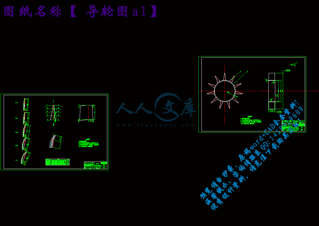
轴流式通风机结构设计【优秀】【word+4张CAD图纸全套】【毕设】

轴流式通风机结构设计【优秀】【word+4张CAD图纸全套】【毕设】

收藏

压缩包内文档预览:

资源预览需要最新版本的Flash Player支持。
您尚未安装或版本过低,建议您

JBT62轴流式通风机总体方案和通风机总体结构设计轴流式通风机结构设计【优秀】【word+4张CAD图纸全套】【毕业设计】【带开题报告+外文翻译+实习总结】【60页正文16400字】【详情如下】【需要咨询购买全套设计请加QQ1459919609】B9.Unsteady Flow Analysis in Hydraulic Turbomachinery.pdf个人工作计划.doc叶轮图a0.dwg壳体a1.dwg学生毕业实习总结.doc导轮图a1.dwg开题报告.doc总装图a0.dwg摘  要.doc译文.doc说明书.doc开题报告1、研究目的和意义在矿井生产过程中,为了准备新水平,新采区和采煤工作面,都必须掘进大量的巷道。在掘进巷道时,为了供给工作人员呼吸新鲜空气,稀释掘进工作面的瓦斯及产生的有害气体,矿尘,并创造良好的气候条件,必须对掘进工作面进行通风。2、国内外发展情况当前世界先进工业国家风机产品开发的主要特点是:1.以节能、节约资源为核心,提高单件效率和耐久性,进而提高整个系统的效率。2.加强系统的自动化、事故警报系统的研制,节省维护、监控方面的人力。3.为提高竞争能力,力求包括附属部件在内的产品标准化和组合化。4.进一步加强了对低噪声、低振动技术的研究。5.不断针对新的需要,开发新的产品。6.在工艺上引进柔性制造系统,最大限度地提高产品生产的自动化程度12。风机产品大多根据用户需要有不同特性要求,多属小批量生产,特别是一些大型风机产品甚至是单件小批生产,对工艺要求复杂。目前国内生产自动化程度很低,而国外通过研制和采用柔性制造系统,提高了生产的自动化程度。以美国为例,中小风机的生产已全部通过自动线完成,从工艺角度提高了产品质量,降低了产品成本8。从产品品种看,发达国家中小型通风机的生产数量和我国大致相当甚至低于我国,但离心、轴流风机的产量约为我国的2倍从85-94年的情况看,离心及轴流风机产量我国为537台,日本为2364台,日本是我国的5倍多,离心风机我国为9980台,而日本高达176911台,是我国的17.7倍。与95年情况对比,我国与之的差距在缩小13。3、研究/设计的目标设计流量Q=5.6m3/s ,全压H=3100pa,效率85%。适合煤矿掘进工作面用的轴流风机。设计的主要内容:JBT62轴流式通风机总体方案设计,叶轮的设计,壳体、集流器、疏流罩、扩散器 、校核计算、外文翻译等。4、设计方案(研究/设计方法、理论分析、计算、实验方法和步骤等)为了适应掘进工作面和巷道狭窄的工况条件,应采用结构紧凑的轴流风机,为了便于拆卸、安装、应设计成多段壳体。风机采用一个电动机驱动二级叶轮的驱动方式,可以减小风机的体积,节约成本。步骤如下:1电动机的选型,根据风量和全压计算出电动机功率选择电动机型号。2风机主要结构形式的确定,根据工况和通风要求选定风机结构。3风机叶轮、导轮的设计,采用相似原理设计风机叶轮。4风机集流器、扩散器、轴的设计,根据工作条件和强度要求设计主要部件。5主要零部件的强度校核,确定设计的合理性。风机机构图如下:方案简图1-轴;2-壳体;3-中导轮;4-后导轮;5-扩散器;6-叶片;7-叶轮;8集流器;9-流线题5、方案的可行性分析风机采用多段壳体设计,满足了采掘面狭小的工作条件,同时便于运输和安装,适合采掘工作面的变化,安装了消声装置,降低了对环境噪声的污染,采用防爆电机,提高了设备的安全性。6、该设计的创新之处风机是一个较强的噪声源。风机在运转中产生的噪声常常成为影响工人健康和干扰环境的祸源。特别是邻近生活区的风机,其进风口和出风口所辐射的空气动力性噪声,更是污染环境的主要因素,形成公害,风机噪音是近年来我国工业部门治理噪声污染的主要对象之一6。本设计在风机上安装了消声装置,有效的降低了风机的噪音,可以减少噪声对人们的听觉、视觉、神经系统、心血管系统、消化系统和内分泌系统的严重危害。7、设计产品的主要用途和应用领域   轴流式风机风压一般在450N/平方米4500N/平方米之间,是主要用来抽吸、输送、提高流体能量的一种机械,主要应用在矿井、隧道、船舰仓室的通风;纺织厂通风、工业作业场所的通风、降温;化工厂高温腐蚀气体的排放;热电厂锅炉的通风、引风;热电站、冶金、化工等冷却塔通风冷却;地下工程、地下发电厂通风;车间空调和原子防护设备的通风等方面。风机的应用非常广泛,简言之主要是用于辅助充分燃烧、通风、输送,几乎涉及国民经济各个领域13。8、时间进程   第  1  周       在学校图书馆查找资料   第  2  周       在鹤岗南山矿实习   第  3  周       在鹤岗南山矿实习第  4  周       整理资料,完成实习总结第  5  周       筹备资料,完成开题报告第  6  周       对轴流式通风机进行总体方案设计第  7  周       主要零部件进行设计第  8  周       主要零部件进行设计第  9  周       对所设计个部分零件进行校核第  10 周       画轴流式通风机总体装配图第  11 周       画轴流式通风机总体装配图第  12 周       画轴流式通风机各部分零件图第  13 周       画轴流式通风机各部分零件图第  14 周       进行外文参考文献的翻译第  15 周       整理说明书和图纸第  16 周       打印说明书和图纸第  17 周       准备答辩9、参考文献1 黄清,陈焕新. 用MATLAB处理通风机性能试验数据.风机技术 , 2005,(02) . 2 盛赛斌. 轴流式风机防堵转控制系统. 华东电力 , 1997,(06) 3 付怀波, 王秉恒. 提高对旋轴流式风机轴承寿命的探讨. 防爆电机 , 2004,(03) 4 杨红军. 风机紧固件的失效和控制措施. 风机技术 , 2005,(02) 5 刘敏. 矿用轴流通风机现场测试技术的研究. 流体机械 , 1996,(12) 6 张弛. 煤矿轴流式风机风井噪声控制方案探讨. 噪声与振动控制 , 1999,(04) 7 吴华淼. 动叶角度可调轴流式风机平衡重块的平衡原理. 华东电力 , 1982,(07) 8 赵艳志, 杜付.风机应用与节能分析. 发电设备 , 2006,(01) 9 苗继军. 变频器在轴流式风机中的应用. 山西煤炭 , 2006,(01) 10吕文灿. 轴流式风机空间流型分析与研究.工程热物理学报 , 1993,(02)  11 陈佐一,叶大均. 叶轮机械内部真实流动研究的某些进展.中国科学基金 , 1996,(02) 12 赵日春, 杨佳仁. 矿井通风机的现场技术改造. 风机技术 , 1997,(04)13 昌泽舟.轴流式通风机实用技术.机械工业出版社,200514 J.P.Van Doormal,G.G.Raithby. Enhancement of the SIMPLEmethod for predicting incompressible fluid flows.NumericalHeat Transfer, 1984, (7) :147-163 15  Korakianitis, T.P. On the Prediction of Unsteady Forces on Gas-Turbine Blades .Part 2:Viscous-Wake-Interaction and Axial-Gap Effects. ASME Paper 88-GT-90, June, 1988 16  Marizo Piller, Enrico Nobile, Thomas J. DNS study of turbulent transport at low Prandtl numbers in a channel flow .Journal of Fluid Mechanics, (458):419-441, 2002 指导教师意见摘  要在矿井掘进巷道时,为了供给工作人员呼吸新鲜空气,稀释掘进工作面的瓦斯及产生的有害气体,矿尘,创造良好工作条件,必须对掘进工作面进行通风。目前对掘进工作面进行通风的主要设备为JBT系列轴流式通风机。本次设计的内容是对JBT62轴流式通风机总体方案和通风机总体结构设计,机械传动部分设计,对轴流风机工作原理,主要工况参数的意义的掌握。具体内容包括:通风方式的选择,总体结构方案的确定,轴的设计和校核计算,叶轮的设计和校核计算,导叶的设计计算,疏流罩、扩散器和集流器的设计和选择,壳体的设计,通风机消声装置的设计,电机的选择和固定方式的设计,联轴器、键和法兰等零件的选型校核。关键词  轴流风机? 局部通风设备? 机械设计AbstractWhen mine pit tunneling tunnel, breathes the fresh air for the supplies staff, the noxious gas which the dilution tunneling working surface's gas and produces, the mine dust, the creation good working condition, must carry on to the tunneling working surface ventilates. At present carries on the well ventilated major installation to the tunneling working surface is the JBT series axial flow type ventilator.This design's content is to the JBT62 axial fans flow type ventilator overall concept and the ventilator gross structure design, mechanical drive part design, to axial-flow fan principle of work, main operating mode parameter significance grasping. The actual content includes: Ventilates the way the choice, the gross structure plan determination, the axis design and the examination computation, impeller's design examines and examines the computation, guide vane's design calculation, sparse class cover, diffuser and current collector design and choice, shell's design, ventilator muffler design, electrical machinery's choice and fixed way design, components and so on shaft coupling, key and flange shaping examinations.Keywords Axial fans Local ventilation equipment Mechanical design目录摘  要IAbstractII第1章 绪论11.1选题的意义11.2主要设计内容11.3国内外同类设备发展状况21.4轴流通风机的工作原理21.5轴流通风机主要工作参数31.5.1风量31.5.2风压31.5.3功率31.5.4效率41.5.5转速41.5.6无因次的流量系数4第2章 轴流通风机总体结构方案设计62.1通风方式的确定62.1.1压入式通风62.1.2抽出式通风72.2结构方案型式82.2.1叶轮92.2.2导叶92.2.3进风口(集流器和整流罩)102.2.4扩散器102.2.5外壳102.2.6轴112.3通风机结构形式的确定112.3.1确定通风机的转速n112.3.2确定通风机的级型式112.3.3确定通风机各级风压比112.3.4叶顶圆周速度ut和叶轮直径D 的选择计算122.4计算电动机功率并选择电机型号13第3章 主要部件的设计计算153.1叶轮参数的设计计算153.1.1流量系数和全压系数的确定153.1.2轮毂比和轮毂直径的确定153.1.3轮毂比检验163.1.4叶片翼型参数的计算183.2叶片翼型的选择213.2.1 LS翼型坐标223.2.2叶片的绘制223.3导轮参数的设计计算233.3.1导轮参数的计算233.3.2导流器叶片几何尺寸的计算253.4导叶翼型的选择253.4.1 圆弧板翼型253.4.2叶片的绘制26第4章 结构部件的设计计算274.1集流器的设计274.2流线罩的设计274.3扩散器的设计284.4轴流通风机轴向间隙的确定304.5轴流通风机径向间隙的确定314.6轴承的选择324.7联轴器的选择334.8风筒的选择344.8.1风筒选用要求344.8.2局部通风机的风筒选型344.9噪音的处理34第5章 主要零部件强度计算365.1叶轮强度计算365.2键的校核385.2.1 键的基本尺寸385.2.2 键的校核385.3轴的校核39第6章 通风机的安装维护和保养416.1通风机安装方法416.2通风机的拆卸416.3通风机的维护416.3.1叶轮的检修426.3.2主轴的检修426.3.3转子的检查436.3.4机壳漏气的检修436.3.5轴承的检修43结论45致谢46参考文献47附录149附录252第1章 绪论1.1选题的意义瓦斯事故历来是煤矿的主要安全事故,因此矿井要防止瓦斯事故的发生。中国矿山安全条例与安全规程规定:向井下供给新鲜风量一般每人不得少于4m3/min,在采掘工作面进风风流中氧气按体积计算不得低于,二氧化碳不得超过。矿井新建、扩建或生产时,都要掘进巷道,在掘进过程中,为了供给工作人员呼吸新鲜空气,稀释和排出自煤(岩)体涌出的有害气体、爆破产生的炮烟和矿尘,以及创造良好的气候条件,必须对掘进工作面进行通风。矿井采掘面通风可以保证人身安全和矿井的安全生产,因此矿井通风有着非常重要的意义。1.2主要设计内容本次设计的内容及工作量是确定JBT62轴流式通风机总体方案设计,总体结构及其组成,掌握轴流风机工作原理,主要工况参数的意义。完成主要机械部分设计。JBT62轴流式通风机过流部件由集流器,叶轮,导叶,扩散器等几部分组成。具体设计内容包括:拟定总体结构方案的确定,轴的设计计算,叶轮的设计计算,导叶的设计计算,疏流罩的设计计算,扩散器的设计计算,集流器的设计计算,壳体的设计,联轴器、法兰等零件的选型校核。保证设计参数流量达到Q=5.6m3/s、全压达到H=3100Pa、效率在以上。此外还包括设计说明书的编写,外文资料的翻译工作。图纸的绘制工作。包括:总体装配图 1张;叶轮零件图 1张;导叶零件图1张;壳体零件图1张;轴零件图1张。1.3国内外同类设备发展状况风机已有悠久的历史。中国在公元前许多年就已制造出简单的木制砻谷风车,它的作用原理与现代离心风机基本相同。1862年,英国的圭贝尔发明离心风机,其叶轮、机壳为同心圆型,机壳用砖制,木制叶轮采用后向直叶片,效率仅为40左右,主要用于矿山通风。1935年,德国首先采用轴流等压风机为锅炉通风和引风;1948年,丹麦制成运行中动叶可调的轴流风机;旋轴流风机、子午加速轴流风机、斜流风机和横流风机也都获得了发展。未来风机发展将进一步提高风机的气动效率、装置效率和使用效率,以降低电能消耗;用动叶可调的轴流风机代替大型离心风机;降低风机噪声;提高排烟、排尘风机叶轮和机壳的耐磨性;实现变转速调节和自动化调节。随着科学技术的不断发展,人们对风机使用的要求也愈来愈高,就目前国外风机技术发展趋势而言,将朝着风机容量不断增大、高效化、高速小型化和低噪音方向发展。高速小型化。各类风机采用三元流动叶轮后,在提高效率的同时,压力也可提高。所以在同等条件下,叶轮外径可减少1030,这样就取得缩小体积和减轻重量的明显效果。提高转速也是风机小型化的重要途径之一。 低噪声化。风机的噪声是工业生产中噪声污染源最主要来源之一。风机大型化和高速化使噪声问题更加突出。对低频噪声,风机主要通过改进风机结构设计,降低本体噪声,若达不到要求,可采取加装消声器等措施。综上所述,这些技术既是国外风机未来发展趋势,也是国内风机行业在技术方面的努力方向。1.4轴流通风机的工作原理轴流风机又叫局部通风机,是工矿企业常用的一种风机,安不同于一般的风机它的电机和风叶都在一个圆筒里,外形就是一个筒形,用于局部通风,安装方便,通风换气效果明显,使用安全,可以接风筒把风送到指定的区域。轴流,就是与风叶的轴同方向的气流(即风的流向和轴平行),如电风扇,空调外机风扇就是轴流方式。风流从集风器沿轴向进入,通过原动机驱动叶轮旋转,使风流获得能量后流入导叶。由于导叶是静止的,其作用是改变风流方向并使风流的部分动能转换为压能。最后,风流通过扩散风筒进一步降低流速,将轴向风流的动能转换为静压能沿轴向排出。1.5轴流通风机主要工作参数风机的性能参数主要有流量、压力、功率,效率和转速。另外,噪声和振动的大小也是主要的风机设计指标。1.5.1风量风量指通风机在单位时间内所输送的气体体积。风机说明书中的风量与风压, 一般均指标准气态下(即大气压力为760mmHg, 温度为, 湿度为, 密度为1.2kg/m3)的数值。风量单位常用的有m3/s, m3/min, m3/h。1.5.2风压风机风压系指全压H, 单位为Pa, 它是单位体积的气体流过风机叶轮时所获得的能量增量。它等于风机的静压与动压之和。一般通风机在较高效率范围内工作时, 其动压约占全压的1020% 左右。1.5.3功率功率是指单位时间内所做的功, 单位 kW(千瓦)。风机的功率可分为:全压有效功率指单位时间内通过风机的空气所获得的实际能量, 它是风机的输出功率, 也称为空气功率。静压有效功率指单位时间内通过风机的空气所获得的静压能量。它是全压有效功率的一部分。轴功率电动机传递给风机转轴上的功率。也就是风机的输入功率。电机功率考虑了传动机械效率和电机容量安全系数后, 电动机的功率。1.5.4效率效率: 表明风机将输入功率转化为输出功率的程度。分为全压效率(也称为空气效率或总效率)和静压效率。1.5.5转速转速系指风机叶轮每分钟的转数, 单位为rad/min。风机转速改变时, 风机的流量、风压和轴功率都将随之改变。参考文献1 黄清,陈焕新. 用MATLAB处理通风机性能试验数据.风机技术 , 2005,(02) . 2 盛赛斌. 轴流式风机防堵转控制系统. 华东电力 , 1997,(06) 3 付怀波, 王秉恒. 提高对旋轴流式风机轴承寿命的探讨. 防爆电机 , 2004,(03) 4 杨红军. 风机紧固件的失效和控制措施. 风机技术 , 2005,(02) 5 刘敏. 矿用轴流通风机现场测试技术的研究. 流体机械 , 1996,(12) 6 张弛. 煤矿轴流式风机风井噪声控制方案探讨. 噪声与振动控制 , 1999,(04) 7 吴华淼. 动叶角度可调轴流式风机平衡重块的平衡原理. 华东电力 , 1982,(07) 8 赵艳志, 杜付.风机应用与节能分析. 发电设备 , 2006,(01) 9 苗继军. 变频器在轴流式风机中的应用. 山西煤炭 , 2006,(01) 10吕文灿. 轴流式风机空间流型分析与研究.工程热物理学报 , 1993,(02)  11 陈佐一,叶大均. 叶轮机械内部真实流动研究的某些进展.中国科学基金 , 1996,(02) 12 赵日春, 杨佳仁. 矿井通风机的现场技术改造. 风机技术 , 1997,(04)13 昌泽舟.轴流式通风机实用技术.机械工业出版社,2005
编号:299871    类型:共享资源    大小:5.28MB    格式:RAR    上传时间:2014-07-27 上传人:QQ14****9609 IP属地:陕西
45
积分
关 键 词:
轴流通风机 结构设计 优秀 优良 word cad 图纸 全套
资源描述:

JBT62轴流式通风机总体方案和通风机总体结构设计

轴流式通风机结构设计【优秀】【word+4张CAD图纸全套】【毕业设计】

【带开题报告+外文翻译+实习总结】【60页@正文16400字】【详情如下】【需要咨询购买全套设计请加QQ1459919609】

B9.Unsteady Flow Analysis in Hydraulic Turbomachinery.pdf

个人工作计划.doc

叶轮图a0.dwg

壳体a1.dwg

学生毕业实习总结.doc

导轮图a1.dwg

开题报告.doc

总装图a0.dwg

摘  要.doc

译文.doc

说明书.doc

开题报告

1、研究目的和意义

在矿井生产过程中,为了准备新水平,新采区和采煤工作面,都必须掘进大量的巷道。在掘进巷道时,为了供给工作人员呼吸新鲜空气,稀释掘进工作面的瓦斯及产生的有害气体,矿尘,并创造良好的气候条件,必须对掘进工作面进行通风。

2、国内外发展情况

当前世界先进工业国家风机产品开发的主要特点是:1.以节能、节约资源为核心,提高单件效率和耐久性,进而提高整个系统的效率。2.加强系统的自动化、事故警报系统的研制,节省维护、监控方面的人力。3.为提高竞争能力,力求包括附属部件在内的产品标准化和组合化。4.进一步加强了对低噪声、低振动技术的研究。5.不断针对新的需要,开发新的产品。6.在工艺上引进柔性制造系统,最大限度地提高产品生产的自动化程度[12]。风机产品大多根据用户需要有不同特性要求,多属小批量生产,特别是一些大型风机产品甚至是单件小批生产,对工艺要求复杂。目前国内生产自动化程度很低,而国外通过研制和采用柔性制造系统,提高了生产的自动化程度。以美国为例,中小风机的生产已全部通过自动线完成,从工艺角度提高了产品质量,降低了产品成本[8]。

从产品品种看,发达国家中小型通风机的生产数量和我国大致相当甚至低于我国,但离心、轴流风机的产量约为我国的2倍从85-94年的情况看,离心及轴流风机产量我国为537台,日本为2364台,日本是我国的5倍多,离心风机我国为9980台,而日本高达176911台,是我国的17.7倍。与95年情况对比,我国与之的差距在缩小[13]。

3、研究/设计的目标

设计流量Q=5.6m3/s ,全压H=3100pa,效率85%。适合煤矿掘进工作面用的轴流风机。

设计的主要内容:JBT62轴流式通风机总体方案设计,叶轮的设计,壳体、集流器、疏流罩、扩散器 、校核计算、外文翻译等。

4、设计方案(研究/设计方法、理论分析、计算、实验方法和步骤等)

为了适应掘进工作面和巷道狭窄的工况条件,应采用结构紧凑的轴流风机,为了便于拆卸、安装、应设计成多段壳体。风机采用一个电动机驱动二级叶轮的驱动方式,可以减小风机的体积,节约成本。

步骤如下:

1.电动机的选型,根据风量和全压计算出电动机功率选择电动机型号。

2.风机主要结构形式的确定,根据工况和通风要求选定风机结构。

3.风机叶轮、导轮的设计,采用相似原理设计风机叶轮。

4.风机集流器、扩散器、轴的设计,根据工作条件和强度要求设计主要部件。

5.主要零部件的强度校核,确定设计的合理性。

风机机构图如下:

方案简图

1-轴;2-壳体;3-中导轮;4-后导轮;5-扩散器;

6-叶片;7-叶轮;8集流器;9-流线题

5、方案的可行性分析

风机采用多段壳体设计,满足了采掘面狭小的工作条件,同时便于运输和安装,适合采掘工作面的变化,安装了消声装置,降低了对环境噪声的污染,采用防爆电机,提高了设备的安全性。

6、该设计的创新之处

风机是一个较强的噪声源。风机在运转中产生的噪声常常成为影响工人健康和干扰环境的祸源。特别是邻近生活区的风机,其进风口和出风口所辐射的空气动力性噪声,更是污染环境的主要因素,形成公害,风机噪音是近年来我国工业部门治理噪声污染的主要对象之一[6]。本设计在风机上安装了消声装置,有效的降低了风机的噪音,可以减少噪声对人们的听觉、视觉、神经系统、心血管系统、消化系统和内分泌系统的严重危害。

7、设计产品的主要用途和应用领域

    轴流式风机风压一般在450N/平方米~4500N/平方米之间,是主要用来抽吸、输送、提高流体能量的一种机械,主要应用在矿井、隧道、船舰仓室的通风;纺织厂通风、工业作业场所的通风、降温;化工厂高温腐蚀气体的排放;热电厂锅炉的通风、引风;热电站、冶金、化工等冷却塔通风冷却;地下工程、地下发电厂通风;车间空调和原子防护设备的通风等方面。风机的应用非常广泛,简言之主要是用于辅助充分燃烧、通风、输送,几乎涉及国民经济各个领域[13]。

8、时间进程

  第  1  周       在学校图书馆查找资料

  第  2  周       在鹤岗南山矿实习

  第  3  周       在鹤岗南山矿实习

第  4  周       整理资料,完成实习总结

第  5  周       筹备资料,完成开题报告

第  6  周       对轴流式通风机进行总体方案设计

第  7  周       主要零部件进行设计

第  8  周       主要零部件进行设计

第  9  周       对所设计个部分零件进行校核

第  10 周       画轴流式通风机总体装配图

第  11 周       画轴流式通风机总体装配图

第  12 周       画轴流式通风机各部分零件图

第  13 周       画轴流式通风机各部分零件图

第  14 周       进行外文参考文献的翻译

第  15 周       整理说明书和图纸

第  16 周       打印说明书和图纸

第  17 周       准备答辩

9、参考文献

1 黄清,陈焕新. 用MATLAB处理通风机性能试验数据.风机技术 , 2005,(02) .

2 盛赛斌. 轴流式风机防堵转控制系统. 华东电力 , 1997,(06)

3 付怀波, 王秉恒. 提高对旋轴流式风机轴承寿命的探讨. 防爆电机 , 2004,(03)

4 杨红军. 风机紧固件的失效和控制措施. 风机技术 , 2005,(02)

5 刘敏. 矿用轴流通风机现场测试技术的研究. 流体机械 , 1996,(12)

6 张弛. 煤矿轴流式风机风井噪声控制方案探讨. 噪声与振动控制 , 1999,(04)

7 吴华淼. 动叶角度可调轴流式风机平衡重块的平衡原理. 华东电力 , 1982,(07)

8 赵艳志, 杜付.风机应用与节能分析. 发电设备 , 2006,(01)

9 苗继军. 变频器在轴流式风机中的应用. 山西煤炭 , 2006,(01)

10吕文灿. 轴流式风机空间流型分析与研究.工程热物理学报 , 1993,(02)  

11 陈佐一,叶大均. 叶轮机械内部真实流动研究的某些进展.中国科学基金 , 1996,(02)

12 赵日春, 杨佳仁. 矿井通风机的现场技术改造. 风机技术 , 1997,(04)

13 昌泽舟.轴流式通风机实用技术.机械工业出版社,2005
14 J.P.Van Doormal,G.G.Raithby. Enhancement of the SIMPLEmethod for predicting incompressible fluid flows.NumericalHeat Transfer, 1984, (7) :147-163

15  Korakianitis, T.P. On the Prediction of Unsteady Forces on Gas-Turbine Blades .Part 2:Viscous-Wake-Interaction and Axial-Gap Effects. ASME Paper 88-GT-90, June, 1988

16  Marizo Piller, Enrico Nobile, Thomas J. DNS study of turbulent transport at low Prandtl numbers in a channel flow .Journal of Fluid Mechanics, (458):419-441, 2002

指导教师意见

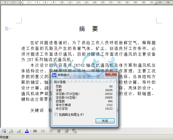
摘  要

在矿井掘进巷道时,为了供给工作人员呼吸新鲜空气,稀释掘进工作面的瓦斯及产生的有害气体,矿尘,创造良好工作条件,必须对掘进工作面进行通风。目前对掘进工作面进行通风的主要设备为JBT系列轴流式通风机。

本次设计的内容是对JBT62轴流式通风机总体方案和通风机总体结构设计,机械传动部分设计,对轴流风机工作原理,主要工况参数的意义的掌握。具体内容包括:通风方式的选择,总体结构方案的确定,轴的设计和校核计算,叶轮的设计和校核计算,导叶的设计计算,疏流罩、扩散器和集流器的设计和选择,壳体的设计,通风机消声装置的设计,电机的选择和固定方式的设计,联轴器、键和法兰等零件的选型校核。

关键词  轴流风机? 局部通风设备? 机械设计

Abstract

When mine pit tunneling tunnel, breathes the fresh air for the supplies staff, the noxious gas which the dilution tunneling working surface's gas and produces, the mine dust, the creation good working condition, must carry on to the tunneling working surface ventilates. At present carries on the well ventilated major installation to the tunneling working surface is the JBT series axial flow type ventilator.

This design's content is to the JBT62 axial fans flow type ventilator overall concept and the ventilator gross structure design, mechanical drive part design, to axial-flow fan principle of work, main operating mode parameter significance grasping. The actual content includes: Ventilates the way the choice, the gross structure plan determination, the axis design and the examination computation, impeller's design examines and examines the computation, guide vane's design calculation, sparse class cover, diffuser and current collector design and choice, shell's design, ventilator muffler design, electrical machinery's choice and fixed way design, components and so on shaft coupling, key and flange shaping examinations.

Keywords Axial fans Local ventilation equipment Mechanical design

目录

摘  要I

AbstractII

第1章 绪论1

1.1选题的意义1

1.2主要设计内容1

1.3国内外同类设备发展状况2

1.4轴流通风机的工作原理2

1.5轴流通风机主要工作参数3

1.5.1风量3

1.5.2风压3

1.5.3功率3

1.5.4效率4

1.5.5转速4

1.5.6无因次的流量系数4

第2章 轴流通风机总体结构方案设计6

2.1通风方式的确定6

2.1.1压入式通风6

2.1.2抽出式通风7

2.2结构方案型式8

2.2.1叶轮9

2.2.2导叶9

2.2.3进风口(集流器和整流罩)10

2.2.4扩散器10

2.2.5外壳10

2.2.6轴11

2.3通风机结构形式的确定11

2.3.1确定通风机的转速n11

2.3.2确定通风机的级型式11

2.3.3确定通风机各级风压比11

2.3.4叶顶圆周速度ut和叶轮直径D 的选择计算12

2.4计算电动机功率并选择电机型号13

第3章 主要部件的设计计算15

3.1叶轮参数的设计计算15

3.1.1流量系数和全压系数的确定15

3.1.2轮毂比和轮毂直径的确定15

3.1.3轮毂比检验16

3.1.4叶片翼型参数的计算18

3.2叶片翼型的选择21

3.2.1 LS翼型坐标22

3.2.2叶片的绘制22

3.3导轮参数的设计计算23

3.3.1导轮参数的计算23

3.3.2导流器叶片几何尺寸的计算25

3.4导叶翼型的选择25

3.4.1 圆弧板翼型25

3.4.2叶片的绘制26

第4章 结构部件的设计计算27

4.1集流器的设计27

4.2流线罩的设计27

4.3扩散器的设计28

4.4轴流通风机轴向间隙的确定30

4.5轴流通风机径向间隙的确定31

4.6轴承的选择32

4.7联轴器的选择33

4.8风筒的选择34

4.8.1风筒选用要求34

4.8.2局部通风机的风筒选型34

4.9噪音的处理34

第5章 主要零部件强度计算36

5.1叶轮强度计算36

5.2键的校核38

5.2.1 键的基本尺寸38

5.2.2 键的校核38

5.3轴的校核39

第6章 通风机的安装维护和保养41

6.1通风机安装方法41

6.2通风机的拆卸41

6.3通风机的维护41

6.3.1叶轮的检修42

6.3.2主轴的检修42

6.3.3转子的检查43

6.3.4机壳漏气的检修43

6.3.5轴承的检修43

结论45

致谢46

参考文献47

附录149

附录252

第1章 绪论

1.1选题的意义

瓦斯事故历来是煤矿的主要安全事故,因此矿井要防止瓦斯事故的发生。中国矿山安全条例与安全规程规定:向井下供给新鲜风量一般每人不得少于4m3/min,在采掘工作面进风风流中氧气按体积计算不得低于,二氧化碳不得超过。矿井新建、扩建或生产时,都要掘进巷道,在掘进过程中,为了供给工作人员呼吸新鲜空气,稀释和排出自煤(岩)体涌出的有害气体、爆破产生的炮烟和矿尘,以及创造良好的气候条件,必须对掘进工作面进行通风。矿井采掘面通风可以保证人身安全和矿井的安全生产,因此矿井通风有着非常重要的意义。

1.2主要设计内容

本次设计的内容及工作量是确定JBT62轴流式通风机总体方案设计,总体结构及其组成,掌握轴流风机工作原理,主要工况参数的意义。完成主要机械部分设计。JBT62轴流式通风机过流部件由集流器,叶轮,导叶,扩散器等几部分组成。具体设计内容包括:拟定总体结构方案的确定,轴的设计计算,叶轮的设计计算,导叶的设计计算,疏流罩的设计计算,扩散器的设计计算,集流器的设计计算,壳体的设计,联轴器、法兰等零件的选型校核。保证设计参数流量达到Q=5.6m3/s、全压达到H=3100Pa、效率在以上。此外还包括设计说明书的编写,外文资料的翻译工作。图纸的绘制工作。包括:总体装配图 1张;叶轮零件图 1张;导叶零件图1张;壳体零件图1张;轴零件图1张。

1.3国内外同类设备发展状况

风机已有悠久的历史。中国在公元前许多年就已制造出简单的木制砻谷风车,它的作用原理与现代离心风机基本相同。1862年,英国的圭贝尔发明离心风机,其叶轮、机壳为同心圆型,机壳用砖制,木制叶轮采用后向直叶片,效率仅为40%左右,主要用于矿山通风。1935年,德国首先采用轴流等压风机为锅炉通风和引风;1948年,丹麦制成运行中动叶可调的轴流风机;旋轴流风机、子午加速轴流风机、斜流风机和横流风机也都获得了发展。未来风机发展将进一步提高风机的气动效率、装置效率和使用效率,以降低电能消耗;用动叶可调的轴流风机代替大型离心风机;降低风机噪声;提高排烟、排尘风机叶轮和机壳的耐磨性;实现变转速调节和自动化调节。随着科学技术的不断发展,人们对风机使用的要求也愈来愈高,就目前国外风机技术发展趋势而言,将朝着风机容量不断增大、高效化、高速小型化和低噪音方向发展。高速小型化。各类风机采用三元流动叶轮后,在提高效率的同时,压力也可提高。所以在同等条件下,叶轮外径可减少10%~30%,这样就取得缩小体积和减轻重量的明显效果。提高转速也是风机小型化的重要途径之一。 低噪声化。风机的噪声是工业生产中噪声污染源最主要来源之一。风机大型化和高速化使噪声问题更加突出。对低频噪声,风机主要通过改进风机结构设计,降低本体噪声,若达不到要求,可采取加装消声器等措施。综上所述,这些技术既是国外风机未来发展趋势,也是国内风机行业在技术方面的努力方向。

1.4轴流通风机的工作原理

轴流风机又叫局部通风机,是工矿企业常用的一种风机,安不同于一般的风机它的电机和风叶都在一个圆筒里,外形就是一个筒形,用于局部通风,安装方便,通风换气效果明显,使用安全,可以接风筒把风送到指定的区域。轴流,就是与风叶的轴同方向的气流(即风的流向和轴平行),如电风扇,空调外机风扇就是轴流方式。风流从集风器沿轴向进入,通过原动机驱动叶轮旋转,使风流获得能量后流入导叶。由于导叶是静止的,其作用是改变风流方向.并使风流的部分动能转换为压能。最后,风流通过扩散风筒进一步降低流速,将轴向风流的动能转换为静压能沿轴向排出。

1.5轴流通风机主要工作参数

风机的性能参数主要有流量、压力、功率,效率和转速。另外,噪声和振动的大小也是主要的风机设计指标。

1.5.1风量

风量指通风机在单位时间内所输送的气体体积。风机说明书中的风量与风压, 一般均指标准气态下(即大气压力为760mmHg, 温度为, 湿度为, 密度为1.2kg/m3)的数值。风量单位常用的有m3/s, m3/min, m3/h。

1.5.2风压

风机风压系指全压H, 单位为Pa, 它是单位体积的气体流过风机叶轮时所获得的能量增量。它等于风机的静压与动压之和。一般通风机在较高效率范围内工作时, 其动压约占全压的10~20% 左右。

1.5.3功率

功率是指单位时间内所做的功, 单位 kW(千瓦)。风机的功率可分为:

全压有效功率─指单位时间内通过风机的空气所获得的实际能量, 它是风机的输出功率, 也称为空气功率。

静压有效功率─指单位时间内通过风机的空气所获得的静压能量。它是全压有效功率的一部分。

轴功率─电动机传递给风机转轴上的功率。也就是风机的输入功率。

电机功率─考虑了传动机械效率和电机容量安全系数后, 电动机的功率。

1.5.4效率

效率: 表明风机将输入功率转化为输出功率的程度。分为全压效率(也称为空气效率或总效率)和静压效率。

1.5.5转速

转速系指风机叶轮每分钟的转数, 单位为rad/min。风机转速改变时, 风机的流量、风压和轴功率都将随之改变。

参考文献

1 黄清,陈焕新. 用MATLAB处理通风机性能试验数据.风机技术 , 2005,(02) .

2 盛赛斌. 轴流式风机防堵转控制系统. 华东电力 , 1997,(06)

3 付怀波, 王秉恒. 提高对旋轴流式风机轴承寿命的探讨. 防爆电机 , 2004,(03)

4 杨红军. 风机紧固件的失效和控制措施. 风机技术 , 2005,(02)

5 刘敏. 矿用轴流通风机现场测试技术的研究. 流体机械 , 1996,(12)

6 张弛. 煤矿轴流式风机风井噪声控制方案探讨. 噪声与振动控制 , 1999,(04)

7 吴华淼. 动叶角度可调轴流式风机平衡重块的平衡原理. 华东电力 , 1982,(07)

8 赵艳志, 杜付.风机应用与节能分析. 发电设备 , 2006,(01)

9 苗继军. 变频器在轴流式风机中的应用. 山西煤炭 , 2006,(01)

10吕文灿. 轴流式风机空间流型分析与研究.工程热物理学报 , 1993,(02)  

11 陈佐一,叶大均. 叶轮机械内部真实流动研究的某些进展.中国科学基金 , 1996,(02)

12 赵日春, 杨佳仁. 矿井通风机的现场技术改造. 风机技术 , 1997,(04)

13 昌泽舟.轴流式通风机实用技术.机械工业出版社,2005


内容简介:
Unsteady Flow Analysis in Hydraulic TurbomachineryAlbert RuprechtInstitute of Fluid Mechanics and Hydraulic MachineryUniversity of Stuttgart, GermanyABSTRACTIn the field of hydraulic machinery Computational Fluid Dynamics (CFD) is routinely used today in re-search and development as well as in design. At that nearly always steady state simulations are ap-plied. In this paper, however, unsteady simulations are shown for different examples. The presentedexamples contain applications with self excited unsteadiness, e. g. vortex shedding or vortex rope inthe draft tube, as well as applications with externally forced unsteadiness by changing or movinggeometries, e. g. rotor-stator interactions. For these examples the requirements, potential and limita-tions of unsteady flow analysis assessed. Particularly the demands on the turbulence models and thenecessary computational efforts are discussed.INTRODUCTIONFor more than a decade Computational Fluid Dynamics (CFD) is used in the field ofhydraulic machinery in research and development as well as in the daily design busi-ness. Early successful demonstrations are given e. g. in the GAMM workshop 1.The applications are steadily increasing. This is expressed in fig. 1, where the per-centage of papers dealing with CFD is shown, which were presented at the IAHRSymposium on Hydraulic Machinery and Cavitation. Starting with Q3D-Euler and 3D-Euler today usually the Rey-nolds averaged Navier-Stokesequations together with a robustmodel of turbulence (usuallythe k- model) is used. It iscommon practice to applysteady state simulations, theunsteadiness in consequence ofthe rotor-stator interactions isaddressed by averaging proce-dures. By this method accurateresults are obtained for manyquestions in the design of com-ponents.However, different problems inturbomachinery arise from un-steady flow phenomena. In or-der to get information on this phenomena or solutions to the problems an unsteadyflow analysis is necessary. This requires a much higher computational effort, roughlya factor 5-10 compared to steady state, depending of the problem and of the degreeof modeling assumptions. With todays computers and software, however, unsteadyproblems can be solved.Fig. 1: Percentage of papers at the IAHR-Symposium dealing with CFDTwo major groups of unsteady problems can be distinguished. The first group areflows with an externally forced unsteadiness. This can be caused by unsteadyboundary conditions or by changing of the geometry with time. Examples are the clo-sure of a valve, the change of the flow domain in a piston pump, or the rotor-statorinteractions. The second group are flows with self excited unsteadiness, which are e.g. turbulent motion, vortex shedding (Karman vortex street) or unsteady vortex be-havior (e. g. vortex rope in a draft tube). Here the unsteadiness is obtained withoutany change of the boundary conditions or of the geometry. There can also occur acombination of both groups (e. g. flow induced vibrations, change of geometrycaused by vortex shedding). All these phenomena can take place in a turbine orpump and require different solution procedures.BASIC EQUATIONS AND NUMERICAL PROCEDURESIn hydraulic turbomachinery today usually the Reynolds averaged Navier-Stokesequations for an incompressible flow are applied. Compared to the steady state themomentum equations contain an additional term prescribing the unsteady change:0xUxUxxP1xUUtUijijjijijiji=?+ (1)ij are the Reynolds stresses, which are calculated from the turbulence model. Thecontinuity equation for incompressible flow reads0xUii=(2)and does not contain a time depending term. It hasto be emphasized that the equations (1) and (2)behaves different in time and in space. In spacethey show elliptic behavior, therefore they requireboundary conditions on all surfaces. In time, how-ever, they are of parabolic nature, which mean thatthere is no feed-back from the future to the pres-ent or past. Because of that no boundary condi-tions are required in the future. This is schemati-cally shown in fig. 2. This is the reason, why thetime discretization is generally carried out in a dif-ferent way than the spatial discretization. For spa-tial discretization usually a Finite Volume or a FiniteElement approximation is applied. For time discre-tization, however, mostly the Finite Differencemethod is used. A few of the most popular finitedifference approximations are shown in fig. 3. Inaddition explicit multi-point schemes of Runge-Kutta-type or predictor-corrector schemes are often applied.Fig. 2: Boundary and initialconditionsFig. 3: Time discretization schemesIt has to be mentioned that the explicit methods require a restriction of the time stepaccording to stability criteria (CFL-criteria), which depend on the local velocities andthe local grid size. The implicit methods, in contrary, are always stable, there is norestriction of the time step. It can be chosen only according to the physical require-ments. In order to obtain accurate solutions the time discretization should be at leastof 2nd order, similar to the spatial discretization. Otherwise extremely small time stepswould be required.The above description of the flow in the Eulerian coordinates can be applied for un-steady boundary condition problems as well as for self excited unsteadiness. How-ever, to express problems with moving geometries in Eulerian coordinates is moredifficult. At the moving boundary a Lagrangian description can be applied very easilysince the fluid particles can be traced by this method. Combining these two methodsan Arbitrary Lagrangian Eulerian (ALE) method can be utilized. This method is suit-able for the solution of problems with moving boundaries. In the ALE method the ref-erence coordinates can be chosen arbitrary. In this referential coordinate system thematerial derivative can be described as()()()()jEijjRiLixt ,xfwutt ,xftt ,xf+=(3)with the coordinatesscooddinateEulerian.x; scooddinatelreferentia.x; scooddinateLagrangian.xEiRiLiand Wi . reference velocity.The momentum equations in the ALE formulation can be written as follows()0xUxUxxP1xUWUtUijijjijijijji=?+(4)The moving of the reference system Wi can be chosen arbitrary. If Wi is equal to zeroone gets the Eulerian description, on the other hand, if wi is equal to the velocity ofthe fluid particle the Lagrangian formulation is obtained. The convective term in thetransport equations for scalar quantities changes in the same way than in the mo-mentum equations. This applies also to the k- and -equations.The numerical realization of moving or changing grids can either be obtained by de-formation of an existing mesh in each time step. For large deformations this requiresan automatic grid smoothing algorithm or even an automatic remeshing after a fewtime steps. An other method is the use of different embedded grids, which can moveagainst each other. In this case a sliding interface between the non-matching grids isrequired. This procedure is schematically shown in fig. 4 for two different problems,namely rotor-stator interaction and vibration of a cylinder in a fluid.In FENFLOSS, the computer code developed at our institute at University of Stutt-gart, the second approach is applied. The interface between the grids is realized bymeans of dynamic boundary conditions, where downstream the node values (veloci-ties and turbulence quantities) are prescribed and upstream pressure and fluxes areintroduced as surfaceconditions. A brief over-view on the numericalprocedures is given in 2,for more details thereader is referred to 3,4.One point has to be em-phasized. Since the un-steady simulations re-quire a severe increaseof computational effortcompared to steady statesolutions, parallel proce-dures are necessary. Inthis case the ALE formulation with moving grids leads to a dynamic change of com-munication because the location of exchange boundaries varies with time and cantherefore change the computational domain of the processors, see 2.In FENFLOSS an implicit solution algorithm is applied. As already mentioned this hasthe advantage that there is no stability limitation for the time step. The overall solutionprocedure including the fluid-structure interaction is shown in fig. 5. If the movementof the grid does not depend on the flow situation the fluid-structure loop vanishes.Fig. 5: Flow chart of FENFLOSS including fluid-structure interactionFig. 4: Moving grid examplesAPPLICATIONSIn the following selected applications are shown and the specific problems for thisexamples are discussed. Firstly some cases with self excited unsteadiness are pre-sented.Vortex shedding at the inlet of a power plantProblem description: The first example shows the flow behavior at the inlet of a low-head power plant. It is an existing plant with two identical bulb turbines. During op-eration the inner turbine showed severe bearing problems whereas the outer turbineoperates smoothly. The reason was expected to be vortex shedding at the inlet. Bynumerical analysis the problem was investigated and it was tried to find a solution tothe problem. In fig. 6 the geometry is shown. The calculation has been carried out in2D as well as in 3D. Firstly it was tried tocarry out a steady state simulation, how-ever, no converged solution could beobtained. Therefore an unsteady simula-tion was undertaken. The results indicatea strong unsteady motion. In fig. 7 thevelocity distribution at a certain time stepis presented. Clearly visible are the vor-tices, shedding from the inlet and movingdownstream into the inner turbine. This isthe reason of thedestruction of thebearings. In or-der to improvethe flow behaviora modified ge-ometry was sug-gested. This ge-ometry, shown infig. 8, has beenbuilt in themeantime. Thereare no longerproblems withvortex shedding. Further detailsabout this application can be foundin 5,6.Discussion: The physical unsteadi-ness of the flow has been indicatedby the inability to achieve a con-verged steady state solution. This isvery often the case with flowsshowing vortex shedding in reality.Fig. 6: Geometry of power plant inletFig. 7: Instantaneous velocity vectors, vortex shedding at theinlet pierFig. 8: Modified geometryA necessary condition for that is, that the numerical scheme does not contain seri-ous artificial diffusion, which would suppress the unsteady motion. The same appliesto the used turbulence model. The standard k- model usually produces a too higheddy viscosity, especially in swirling flows, and therefore it very often suppresses theunsteady motion. This will be discussed again in other applications. For many casesat least a streamline curvature correction or even a non-linear eddy viscosity formu-lation is necessary in order to avoid a too high turbulence production.Another point in turbulence modeling is the treatment of the near wall flow. It is wellknown that the use of wall functions usually tends to predict a flow separation toolate. In case of vortex shedding this can cause a severe reduction of the vortex sizesor even a complete suppression of the vortices. More accurate results can be ob-tained by solving the flow up to the wall (if possible) by a low-Reynolds- or a two-layer model. The results shown above are achieved by an algebraic turbulencemodel (Baldwin-Lomax-type) where the flow is resolved up to the wall.Vortex rope in a draft tubeProblem description: As an other self excited unsteady flow example the simulationof a vortex rope in a draft tube is shown. Here a straight axisymmetrical diffuser isconsidered. The inflow conditions to the diffuser are chosen according to the partload operation of a Francis turbine. This means that the flow shows a strong swirlcomponent. The inlet velocity distribution and the geometry are presented in fig. 9.The instantaneous flow for a certain time step is given in fig. 10, where an iso-pressure surface as well as the secondary velocity vectors in three cross-sectionsare plotted. Clearly the cork-screw type flow with an unsymmetrical form is visible,although the geometry and the boundary conditions are completely axisymmetrical.Fig. 9: Geometry and inlet conditionsFig. 10: Iso-pressure and secondary flow of a vortex ropeIn fig. 11 the secondary velocity and the low pressure region, which represents thevortex center, is shown in the cross-section S, indicated in fig. 9, for certain timesteps. Clearly the revolution of the vortex center can be observed. This, of course,causes pressure fluctuations and therefore dynamical forces on the draft tube sur-face.Fig. 11: Secondary motion and low pressure region for different time stepsDiscussion: Concerning the numerical scheme and the turbulence models the dis-cussion above also applies here, e. g. application of the standard k- model leads toa steady state, symmetrical solution. This is also reported in 7. The results shownabove are achieved by applying the multi-scale k- model of Kim 8 together with astreamline curvature correction. This model shows a much lower eddy viscosity thanthe standard model, especially in swirling flows. The application of wall functionsdoes not give any problems here, since the flow instability has its origin in the centerand is not affected by the prediction of the near-wall region.Vortex instability in a pipe trifurcationProblem description: In the following anotherproblem caused by a vortex instability isshown. It is a pipe trifurcation, which is es-tablished in a power plant in Nepal. The tri-furcation distributes the water from the pen-stock to the three turbine units. The prob-lem in this plant arises from severe fluctua-tions of the power output of the both outerturbines. By field measurements the trifur-cation was discovered as the reason for thefluctuations. By means of CFD and bymodel tests, carried out at ASTROE in Graz,the flow behavior should be analyzed and acure of the problem should be found. Thegeometry of the trifurcation is shown in fig. 12. It hasa spherical shape.The fluctuation in the trifurcation is caused by astrong vortex, which tends to be unstable. It skipsbetween the two situations, sketched in fig.13. In themodel tests the secondary velocity of the vortex couldbe found to be 30 times higher than the transportvelocity. The reason is that at the top of the spherethere is enough space for a huge vortex to form. Thisvortex concentrates in the side branches and there-fore increases the swirl intensity. Because of thisstrong secondary motion there are strong losses atthe inlet of the branch, which reduces the head of the turbine and therefore causesthe reduction of power output.During the project it was tried to obtain the unsteady behavior by a k- simulation onrelatively coarse grids (200-300.000 nodes). However, these calculations did notshow the vortex instability. Merely a vortex forms which extends from one sidebranch to the other. The swirl intensity was underpredicted by more than a factor five.Because of the low swirl rate the vortex is completely stable and has no tendency ofskipping between different stations. Even by a dynamical excitation caused bychanges of the outlet boundary condition of one branch the predicted vortex did notchange its position.Only when applying finer grids and another turbulence model the predicted swirl in-tensity could be increased. Here an algebraic turbulence model with a limitation ofthe eddy viscosity is applied. The used grids consists of about 500 000 nodes. As aconsequence this leads to an instability of the vortex. In the prediction the vortexskips between the two structures shown in fig. 14. One of these structures corre-sponds quite well with the structure observed in the model tests. In the second situa-tion the vortex expends from one side branch to the other. This complies with theabove mentioned stable results. The calculated swirl intensity is still more than twotimes lower compared to the results of the model tests. Therefore further investiga-Fig. 12: Geometry of the trifurcationFig. 13: Vortex structuretions with other turbulence models and with finer grids are necessary and will be car-ried out in future.Fig. 14: Predicted vortex structuresFor completeness the solution to the problem isshown. It consists of the installation of two platesin the upper and lower part of the sphere. This isshown in fig. 15. Hence no free space is available,where the vortex can form. Consequently the in-tensity of the vortex is dramatically reduced andthe vortex is completely stable. In the meantimethe reconstruction was carried out and the fluctua-tion of the power output vanished. As a by-productthe losses in the trifurcation are severely reduced,which results in an increase of power output of ap-proximately 5%. Further details of this problem canbe found in 9,10.Discussion: As already mentioned the calculations using the k- model were notsuccessful. It is well known that this model is not able to predict highly swirling flowsaccurately. The unsteady motion of the vortices (especially of very slim vortices),however, very much depends on the swirl intensity. In order to prescribe such typesof flow with sufficient accuracy it is necessary to have highly sophisticated turbulencemodels and very fine grids, maybe the only way to achieve it is the application oflarge eddy simulation.Rotor-stator interaction in an axial tubineThe following ex-ample belongs tothe second group,the unsteadinessis forced by mov-ing geometries.The problem inquestion is theFig. 15: Modified geometryFig. 16: Geometry of the investigated axial turbineflow in an axial turbine. The speciality of this turbine is its relatively low specificspeed. It has been designed for pressure recuperation in piping systems. The ad-vantage is that the discharge is nearly independent of the speed, because of that theturbine cannot introduce waterhammers in the system. The geometry of the turbine isshown in fig. 16. It consists of the inlet confuser, 12 fixed guide vanes, 15 runnerblades and the draft tube. The stator and rotor part is shown in more detail in fig. 17.For the simulation the complete turbine is considered including all flow channels inthe guide vanes and in the runner, although a symmetry condition of 120 could beused. The reason is, that also a variant with unsymmetrical outlet has been investi-gated.The computational mesh consists of more than 2 million grid nodes, part of the gridis shown in fig. 18. These are roughly 60000 nodes per flow channel. It is a rathercoarse grid, considering that the clearance between runner blades and casing has tobe included in the model, which is necessary since the clearance flow very much af-fects the channel flow because of the short runner blades. The calculations are car-ried out using the standard k- model.In the following someresults of the calcu-lation will be shown.In fig. 19 the instan-taneous flow in therunner is presented.The figure shows thepressure distributionof the runner surfaceas well as stream-lines started at dif-ferent locations.Looking at the pres-sure one clearly seesthe stagnation pointat the leading edge.The location of theDraft tubeguide vanesrunnerFig. 18: Part of the computational meshFig. 17: Geometry of rotor and statorFig. 19: Instantaneous flow in the runnerstagnation point varies slightly with the runner position. Generally the inlet flow angleseems to be slightly too flat. Therefore the stagnation point is shifted towards thesuction side. Considering the flow in the tip clearance one can observe that at theinlet the shear forces dominate. The flow tends to go from the suction to the pressureside. In the second half of the blade the pressure forces dominate. The flow in theclearance goes from the pressure to the suction side. It can already be seen by thisresults that the design of the runner is not optimal. This is a first version, in themeantime a much better runner has been designed. However this geometry is nu-merically investigated since extensive measurements have been carried out for thisconfiguration and the numerical results can be validated.In fig. 20 again the instantaneous pressure for a certain time step is shown. One canobserve the low pressure region on the suction side at the top of the runner blades.Clearly visible is the variation of the pressure with the position. The low pressure re-gion corresponds quite well with the cavitation observation at the test rig, see fig. 21.There one also can observe the variation of the cavitation bubbles according to therunner position.As a quantitative compari-son the pressure at twolocations is shown in fig.22. Position 1 is located infront of the guide vanesand the second positionlies between the guidevanes and the runner. Atboth locations the meas-ured and the calculatedpressure correspondsquite well. One can seethat even in front of theguide vanes pressurefluctuations can be ob-served. Between the statorFig. 20: Calculated pressure distribution fora certain runner positionFig. 21: Cavitation observation in therunnerFig. 22: Pressure distribution at two spot pointsand the rotor fluctuations of nearly 25% of the head of the turbine can be seen. This,of course, leads to dynamical forces on the blades. In fig. 23 the torque on one run-ner blade as well as the torque of the complete runner is shown. The calculatedtorque fluctuation on a single blade arenearly 30% of the averaged torque. Thisis a dynamical force on the blading. Thetotal torque, however, is nearly constantdue to the great number of blades anddue to different phases of the fluctua-tions. Further details concerning the tur-bine and the measurements are pub-lished in 11, details on the calculationsare given in 12.Discussion: Since the unsteadiness of theflow is forced by the changing of the ge-ometry this problem is easier to attackthan the examples shown above. Heresufficient results are obtained applyingthe same models than in steady statesimulations and similar criteria apply foraccuracy than for the steady state simulations. As seen in the comparison with themeasurements the prediction of pressure (but also of velocities which are not shownhere, see 12) is quite accurate. Therefore this kind of calculation is suitable to pre-dict dynamical forces.POTENTIAL, LIMITATIONS, REQUIRED RESOURCESThe applications show that many unsteady problems can be investigated by CFD andmany phenomena can be studied, even rather complicated ones. Here we will dis-cuss again the potential and the limitations as well as the required resources, whichare necessary for an unsteady simulation.Firstly the rotor-stator problem is discussed. It can be said, that for this type of flowthe unsteady computations behave similar to steady state. The accuracy principallydepends on the grid size and on the turbulence model used as in steady state. Thereasons for inaccuracy also correspond very close to that of steady state simulations,e. g. wake flow, swirling flow etc.It has to be pointed out, that the requirements of computational effort for unsteadyflows is much higher than for steady state. Looking at a single component an un-steady simulation needs at least 3-5 times more computing time. But due to the ab-sence of any periodicity the complete turbine including all stator and rotor channelshave to be considered, in opposition to steady state, where periodicity can be appliedby circumferential averaging. Depending on the type of machine and on the numberof guide vanes and runner blades the necessary grid nodes can be increased by afactor of 20-30, to achieve a similar accuracy.Another problem for unsteady computations of a complete turbine or pump is, thatthe flow contains a large range of frequencies. In order to resolve the high frequen-Fig. 23: Torque on a runner bladescies sufficiently accurate a small computational step has to be chosen. This, how-ever, results in very long computational times when also low frequency phenomenahave to be resolved, see 2.Concerning the self excited vortex flow qualitative predictions can be obtained. Thephenomenon of vortex shedding can be calculated quite accurate. Even if the de-tailed flow behavior may not be kept completely correct the frequencies and ampli-tudes of integral quantities (e. g. forces) can be predicted with sufficient accuracy formost of the problems. Flow instabilities and correct vortex movements, however, de-pend very much on the detailed flow situation. Even small changes of velocity canhave a great response in the flow structure. As an example the flow in the sphericaltrifurcation is mentioned. There the vortex instability strongly depends on the swirlingrate. This means it is essential to predict the highly swirling flow very accurate, butthat is a severe problem for all the turbulence models used in practice today. At leastit is necessary to apply non-linear models or Reynolds-stress models, since swirlingflows are dominated by anisotropic effects. Maybe sufficient results can only beachieved by Large Eddy Simulations.Because the vortices are often very concentrated and consequently show very steepgradients their prediction require very fine computational grids. If the vortices movewith time a self adaptive mesh refinement would be desirable. This, however, israther complicated. Since the required computational effort is very high, parallelcomputing must be applied in order to obtain reasonable response times. An adap-tive grid generation then leads to a dynamical load distribution. Both of the two ap-proaches, either using extremely fine grids in total geometry or using adaptivemeshes with dynamical load balancing, leads to a computational effort, which is atleast 20 times higher than a similar steady state solution.CONCLUSIONSUnsteady simulations for the different applications have been shown, among themare applications dominated by vortex shedding or vortex instabilities as well as appli-cations with forced unsteadiness which is e. g. rotor-stator interactions. All simula-tions have in common a quite large requirement of computational resources. Espe-cially for rotor-stator interactions the complete turbine has to be considered and allflow channels in the stator as well as in the rotor have to be included. This leads tomany grid nodes and an
温馨提示:
1: 本站所有资源如无特殊说明,都需要本地电脑安装OFFICE2007和PDF阅读器。图纸软件为CAD,CAXA,PROE,UG,SolidWorks等.压缩文件请下载最新的WinRAR软件解压。
2: 本站的文档不包含任何第三方提供的附件图纸等,如果需要附件,请联系上传者。文件的所有权益归上传用户所有。
3.本站RAR压缩包中若带图纸,网页内容里面会有图纸预览,若没有图纸预览就没有图纸。
4. 未经权益所有人同意不得将文件中的内容挪作商业或盈利用途。
5. 人人文库网仅提供信息存储空间,仅对用户上传内容的表现方式做保护处理,对用户上传分享的文档内容本身不做任何修改或编辑,并不能对任何下载内容负责。
6. 下载文件中如有侵权或不适当内容,请与我们联系,我们立即纠正。
7. 本站不保证下载资源的准确性、安全性和完整性, 同时也不承担用户因使用这些下载资源对自己和他人造成任何形式的伤害或损失。
提示  人人文库网所有资源均是用户自行上传分享,仅供网友学习交流,未经上传用户书面授权,请勿作他用。
关于本文
本文标题:轴流式通风机结构设计【优秀】【word+4张CAD图纸全套】【毕设】
链接地址:https://www.renrendoc.com/p-299871.html

官方联系方式

2:不支持迅雷下载,请使用浏览器下载   
3:不支持QQ浏览器下载,请用其他浏览器   
4:下载后的文档和图纸-无水印   
5:文档经过压缩,下载后原文更清晰   
关于我们 - 网站声明 - 网站地图 - 资源地图 - 友情链接 - 网站客服 - 联系我们

网站客服QQ:2881952447     

copyright@ 2020-2025  renrendoc.com 人人文库版权所有   联系电话:400-852-1180

备案号:蜀ICP备2022000484号-2       经营许可证: 川B2-20220663       公网安备川公网安备: 51019002004831号

本站为文档C2C交易模式,即用户上传的文档直接被用户下载,本站只是中间服务平台,本站所有文档下载所得的收益归上传人(含作者)所有。人人文库网仅提供信息存储空间,仅对用户上传内容的表现方式做保护处理,对上载内容本身不做任何修改或编辑。若文档所含内容侵犯了您的版权或隐私,请立即通知人人文库网,我们立即给予删除!