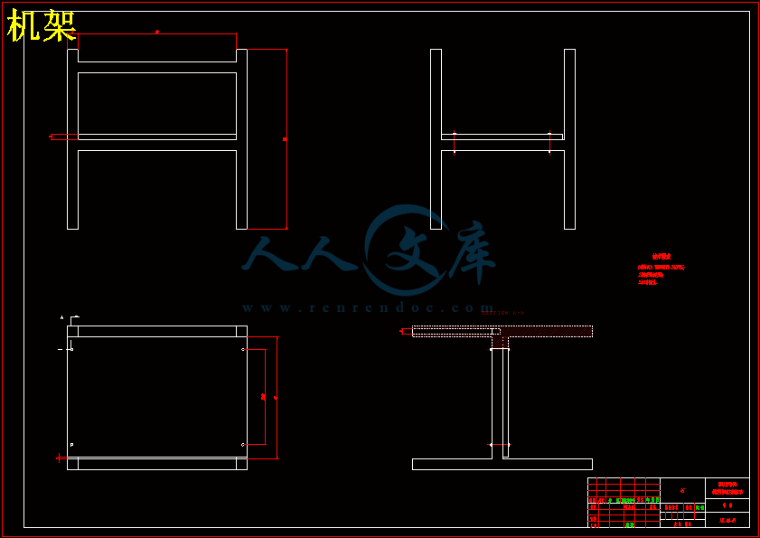
装配图.dwg
装配图.dwg

回转体质心位置检测设备的设计【4张CAD图纸】【优秀】

收藏

压缩包内文档预览:
预览图
编号:300025    类型:共享资源    大小:1.29MB    格式:RAR    上传时间:2014-07-28 上传人:上*** IP属地:江苏
45
积分
关 键 词:
回转体 质心位置 检测设备 设计 cad图纸
资源描述:

回转体质心位置检测设备的设计

24页 4300字数+说明书+任务书+外文翻译+4张CAD图纸【详情如下】

任务书.doc

回转体质心位置检测设备的设计论文.doc

外文翻译--应力为基础的有限元方法应用于灵活的曲柄滑块机构.doc

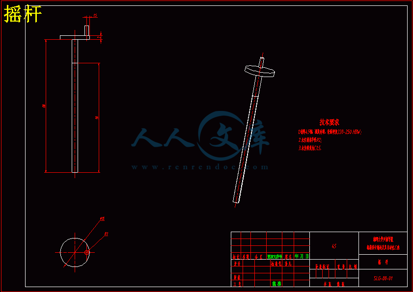
摇杆.dwg

机架.dwg

脚轮.dwg

装配图.dwg

目录

·摘要2

·Abstract3

第一章 绪论4

1.1 国内外现状4

1.2 研究的目的和意义4

第二章 方案设计5

2.1方案设计一5

  2.1.1质心和质量检测装置.5

  2.1.2工件质心检测的基本原理5

2.2 方案设计二11

2.2.1结构组成11

2.2.2检测工件的基本原理11

   2.2.3质心的三点法测量原理12

   2.2.4选择-------------------13

第三章 手动升降台的设计14

3.1结构组成14

   3.1.1 工作原理14

3.1.2 摇杆的设计15

3.1.3升降杆的设计16

   3.1.4轴承的设计17

3.1.5上底板的设计18

   3.2升降台的上升说明-19

总结感谢23

参考文献24

回转体质心位置检测设备的设计

摘要 本文主要从工程的角度上探讨了非均匀回转体工件采用四点旋转法检测质心的方法。并利用此方法初步设计了质心和质量的自动检测装置。 在装置中,采用了同步带传动机构及摩擦驱动装置,并采用了液制系统进行驱动检测参数要求的换位和摩擦轮的压力调节,保证了检测装置的正确位置和摩擦轮接触正压力的有效工作范围。

    在驱动方式上,采用了直接转矩控制和速度控制两种控制模式,以应付不同参数检测的要求,使其机械系统运行更加平稳。针对每种参数的检测传感器,分别配用了相应的信号放大电路、滤波电路和检测数据处理的专用单片机系统,使各个参数的检测自成系统。各参数的单片机采用内部通信方式将各单片机系统有机结合,通过主单片机系统进行协调与调度,使系统具有进行数据处理的能力,保证了相关参数检测的同步性,从而克服了因程序流程造成的时间差异引起的检测误差,使

检测系统的适时精度得到提高。为保证各传感器检测的信号具有足够高的分辨率,采用了微伏级高精度稳压电电源和具有微处理器的24位A/D转换器ADS1211,并设计了相应的高精度信号放大器和低通滤波器。    

关键词质心    滤波器    分辨率

Design of rotary centroid position detection equipment

· Abstract

This paper mainly from the point of view of project and discusses the method of non uniform revolving body workpiece with four rotating method to detect centroid. And preliminary design of the center of mass and the quality of the automatic detection device using this method.

In the device, the synchronous belt transmission mechanism and a friction drive device, and the liquid system requires the drive parameters of the transposition and friction wheel pressure regulation, ensure the effective working range of the correct position and friction wheel contact detecting device of positive pressure.

In a driving way, using the direct torque control and speed control of two kinds of control mode, to meet different detecting, the mechanical system run more smoothly. For every sensor parameters, respectively, a signal amplifying dedicated  microcontroller system circuit, filter circuit and the testing data processing, a system of testing the parameters. The parameters of the single-chip microcomputer with internal communication mode combines the MCU system, coordination and scheduling by principal microcomputer system, so that the system has the ability of data processing, to ensure the synchronization parameters detection, thus overcoming the detection error caused by time difference caused by the process, so that the

To improve the precision of detection system. To ensure the signal of each sensor has high enough resolution, using the 24 bit A/D converter ADS1211 microvolt precision regulated power supply and a microprocessor, and the design of high precision signal amplifier corresponding and low pass filter.

· keyword

Centroid  filter   resolution

第一章 绪论

当一个回转体工件制作完场后,根据使用要求往往需要知道较精确的质心位置,用以准确计算工件的动力学特性。对于质量分布均匀的工件,比较简单,可以直接计算出来,但对于非均匀工件,特别是非均匀组装件的计算则比较困难,而且还很难保证精确度。因此需要利用相应的检测装置,将这些参数直接而准确地检测出来。

1.1国内外现状

    目前国内外普遍使用的质心检测方法主要有三点测量法,四点测量法等;常用的转动惯量检测方法主要有三线摆法、能量法、转动法和扭转震动和振幅测定法等。

   美国Space Electronios公司目前是航天大尺寸物体质量性能测量的领先者。所销售的转动惯量测试仪大约是世界上其他公司销量的总和。其质心测量仪是目前世界上最准确的。其成功的一个主要原因是采用了无摩擦气体轴承和平衡力矩测量技术。独特的气体轴承设计可以在一台机器上一次测量动平衡度、转动惯量、质心质量。

    国内西安交通大学现代设计及转子轴承系统教育部重点实验室采用扭摆震动振幅测试法,对轴向最大负荷为10KN的转动惯量测试台磁悬浮系统的电磁阻尼进行了试验研究,结果表明该磁悬浮系统中,向心电磁轴承的电磁阻尼起决定性作用。同时还采用有限元法和级数法对电磁推力轴承和径向轴承中的电磁场进行了计算,理论计算的结果与实验测量的结果有很好的一致性,转动惯量的计算值与实验值的误差仅为1.09%。  

1.2研究的目的和意义

    目的是要解决长径较大的非均匀质量分布回转体工件的质心和质量的检测问题。同时提出多设备同时检测的数据通信网络的构建方法,为今后的多检测设备、多参数同时检测并进行产品的整体系统动态测试和混合仿真试验分析打下基础。  

第二章  设计方案

2.1设计方案一

2.1.1质心和质量检测装置

结构组成:检测装置有检测平台、摩擦驱动轮组、支撑轮组、测力传感器和测力平台及液压系统等部分组成,(图1)。

2.1.2工件质心检测基本原理

    将工件放置在检测装置中、启动质心检测功能,这时检测平台由四个对称分布的测力传感器顶起脱离平台支撑面(图二)由摩擦驱动轮组驱动被测工件做定轴转动。工件每转90度为一个质心检测位置,每个检测位置工件都停下来,摩擦轮组离开支撑轮组(见下图)。一个位置检测完毕后,摩擦轮组在油缸的驱动下置位,将工件顺着原方向再转90度,摩擦轮组重新离开支撑轮组,周而复始,直到一周的四个位置全部检测完毕。工作原理

   向右摇动手轮带动连杆转动、连杆上的螺纹和推动块的螺纹相啮合,推动块向轴向固定块移动,此时上底板开始上升,当推动块接触轴向固定块时;升降工作台达到最高值;向左摇动手轮,推动块向首轮移动升降台开始下架,当推动块接触固定块时升降台达到最低点。  如上图所示手轮和连杆固定在一起叫摇杆,手轮直径145mm,厚度63mm,连杆长度620mm,直径28mm;

   连杆螺纹的设计

  大径     30.1625mm

  小径     28.48356mm

  螺距     1.41224mm

  角度     60

  轴尺寸   29.94152mm

  方法            剪切

  成型            统一标准

  螺纹头数        1

  长度            500mm

  3.1.3升降杆的设计

升降杆有四根,上底板就是由升降杆提供的向上的力,两根连杆之间由销连接。而连杆的两头分别连接上底板和轴承。   到现在为止,论文基本已经定稿,想到开始的时候我基本不知道怎么动手,现在却可以说完成的相当理想的情况,这期间可以说是一个探索的过程,碰到了不少的新鲜东西,也用到了不少旧的事物。这次的毕业设计对我来说是一个考验,这会为我未来的工作奠定一个良好的基础。

   在这次毕业设计中,软件的使用必不可少,尤其是NX。这次毕业设计使我运用软件方面有了不少的提高,为以后工作的展开有坚实的基础。其中不少东西涉及我们平时所学,为了完成毕业设计我不得不重新拾起旧的记忆,所以这次相当让我对大学知识的一次归纳,使我爱上我的专业。在这次毕业设计中我也充分认识自己的不足,实践和理论还是存在差别的,只有不断的积累经验了,才能真正做到学所有用。

   这次毕业设计的题目、设计具体细则是在马秋成老师的悉心指导下完成的。老师在毕业设计的过程中付出了很多,因此,时至今日,请容许我像我的老师表示由心的感谢。?

   在将来我会向这次毕业设计一样,用一样的热情和态度去加强理论和实践的结合去迎战新的挑战。  

参考文献

【1】濮良贵, 纪名刚. 机械设计[M]. 北京:高等教育出版社,2006.

【2】罗圣国.吴宗泽. 机械设计课程设计手册[M]. 北京:高等教育出版社,2006.

【3】李必文.机械精度设计与检测[M]. 长沙:中南大学出版社,2011.              

【4】潘存云,唐先进. 机械原理[M]. 长沙:中南大学出版社,2011.    

【5】卢志辉、孙志扬、陈惠南、李祥云、费星如;旋转体质心形心和质心横偏量的测量机构设计及精度分析【J】机械设计;2010(04)  

【6】曾敏、陈东;固体火箭发动机质心计算测量研究【J】计算机测量与控制;2010(09)

【7】于治会;下卧式径向偏心仪【J】宇航计测技术;1995(02)

【8】朱俊杰、陈田英、蔺美俊;正确选择和使用电子天平【J】宇航计测技术;1997(04)

【9】吴庆鸣、涂志国、杨文清、李国超;发动机质心测量方案研究【J】航空制造技术;2003(11)

【10】张可强;复杂回转体零件简易质心测量装置的设计《机械工程师》2008(12)

【11】郑宾、侯文、杨瑞峰;大尺寸柱状结构质量、质心测量方法【J】测试技术学报;2002(02)

【12】刘建营;固体火箭发动机质心测量技术述评【J】固体火箭技术;1991(04);

【13】成大先.机械设计手册:第3卷[M].第四版.北京:化学工业出版社,2002.

【14】濮良贵,纪名刚. 机械设计(第八版)[M].北京:高等教育出版社,2006.

内容简介:
湘潭大学兴湘学院毕业论文(设计)任务书论文(设计)题目: 回转体质心位置检测设备的设计 学号: 2010963027 姓名: 孙凡 专业: 机械设计制造及其自动化 指导教师: 马秋成 系主任: 刘柏希 一、主要内容及基本要求 设计一台用于检测回转体质心位置的设备。要求能检测出长圆柱形装配体的在三个坐标方向质心位置参数,并能根据质心位置参数计算出配重质量和位置.检测原理可以采用四点法检测。已知参数和主要技术要求如下: 1、被检对象的最大长度4000mm,最大直径220mm;最大重量300kg。 2、检测精度,位置偏差小于3mm; 3、产品结构紧凑、工作可靠,并要求2班制连续工作; 4、测量参数能在电脑上实时显示; 设计基本要求 1、按以上技术要求,完成质心位置检测设备的方案设计; 2、应用UG软件进行产品的三维建模和工程图设计 3、设计计算说明书1份; 4、装配图1张,其他零件图若干,图纸总工作量折合成零号图不少于2.5张 5、翻译英文资料(3000单词左右)。 二、重点研究的问题 1、质心的测试方法; 2、质心的位置计算。 三、进度安排序号各阶段完成的内容完成时间1UG软件学习及知识准备12周2文献检索与资料查阅3周3总体技术方案设计及计算45周4产品的三维建模69周5总装配图绘制10周6详细设计并绘零件图 1112周7撰写设计计算说明书13周8毕业答辩14周四、应收集的资料及主要参考文献 1濮良贵,纪名刚. 机械设计M. 北京:高等教育出版社,2002. 2胡宗武等. 非标准机械设备设计手册M. 北京:机械工业出版社,2005. 3 机械设计的相关手册 4 UG建模的相关书籍 5 回转体质心检测的相关专利 湘潭大学兴湘学院毕业论文(设计)鉴定意见 学号: 2010963027 姓名: 孙 凡 专业: 机械设计制造及其自动化 毕业论文(设计说明书) 25 页 图 表 4 张论文(设计)题目: 回转体质心位置检测设备的设计 内容提要: 主要内容是找出检测质心和转动惯量的方法,使之能在一套检测装置上检测工件的质量、质心和转动惯量,并能在加工制造要求不十分严格的条件下获得较高的检测精度。为适应工件的实际工作情况的静态和动态计算分析要求,检测装置还要同时具有单次和连续检测。本文主要采用了四点旋转法检测质心和根据刚体转动定理利用旋转法检测转动惯量的方法;研究的目的是要解决回转体的质心和转动惯量的检测问题.目前国内外普遍使用的质心检测方法主要有三点测量法,四点测量法等;常用的转动惯量检测方法主要有三线摆法、能量法、转动法和扭转震动和振幅测定法等。美国Space Electronios公司目前是航天大尺寸物体质量性能测量的领先者。所销售的转动惯量测试仪大约是世界上其他公司销量的总量和其质心测量仪是目前世界上最准确的。其成功的一个主要原因是采用了无摩擦气体轴承和平衡力矩测量技术。独特的气体轴承设计可以在一台机器上一次测量动平衡度、转动惯量、质心质量。国内西安交通大学现代设计及转子轴承系统教育部重点实验室采用扭摆震动振幅测试法,对轴向最大负荷为10KN的转动惯量测试台磁悬浮系统的电磁阻尼进行了试验研究,结果表明该磁悬浮系统中,向心电磁轴承的电磁阻尼起决定性作用。同时还采用有限元法和级数法对电磁推力轴承和径向轴承中的电磁场进行了计算,理论计算的结果与实验测量结果有很好的一致性,转动惯量计算值与实验值的误差仅为1.09%。指导教师评语 孙凡同学毕业设计期间,针对装配回转体质心位置检测问题,查阅了相关文献资料,采用四点法进行了质心位置检测装置的设计,应用UG软件建立了虚拟装配模型,绘制了二维工程图。所设计的质心位置检测装置,原理正确,方案可行,但非测量位置太高,不便于操作,局部装配关系表达不清楚,图纸尺寸标注欠规范。 同意参加毕业答辩,建议评定成绩“中”。指导教师: 年 月 日 答辩简要情况及评语 根据答辩情况,答辩小组同意其成绩评定为答辩小组组长: 年 月 日答辩委员会意见经答辩委员会讨论,同意该毕业论文(设计)成绩评定为答辩委员会主任: 年 月 日湘潭大学兴湘学院毕业论文(设计)评阅表学号 2010963027 姓名 孙 凡 专业 机械设计制造及其自动化 毕业论文(设计)题目: 回转体质心位置检测设备的设计 评价项目评 价 内 容选题1.是否符合培养目标,体现学科、专业特点和教学计划的基本要求,达到综合训练的目的;2.难度、份量是否适当;3.是否与生产、科研、社会等实际相结合。能力1.是否有查阅文献、综合归纳资料的能力;2.是否有综合运用知识的能力;3.是否具备研究方案的设计能力、研究方法和手段的运用能力;4.是否具备一定的外文与计算机应用能力;5.工科是否有经济分析能力。论文(设计)质量1.立论是否正确,论述是否充分,结构是否严谨合理;实验是否正确,设计、计算、分析处理是否科学;技术用语是否准确,符号是否统一,图表图纸是否完备、整洁、正确,引文是否规范;2.文字是否通顺,有无观点提炼,综合概括能力如何;3.有无理论价值或实际应用价值,有无创新之处。综合评 价 孙凡同学在毕业设计期间,认真研究了回转体质心位置检测问题,查阅 了很多文献,最终确定了四点旋转法测量质心位置。在这期间努力学习UG等画图软件,并且用UG建立了装配模型,生成了二维图,虽然很久简单,但是创意新颖、简单、实用;只是二维图布局不合理,尺寸标注欠规范,局部表达不清楚。评阅人: 年 月 日湘潭大学兴湘学院毕业设计说明书题 目:回转体质心位置检测设备的设计学 院: 兴湘学院 专 业:机械设计制造及其自动化学 号: 2010963027 姓 名: 孙 凡 指导教师: 马秋成 完成日期: 2014年5月8号 湘潭大学兴湘学院毕业设计说明书题 目: 回转体质心位置检测设备的设计 专 业: 机械设计制造及其自动化 学 号: 姓 名: 指导教师: 完成日期: 2014年5月8号 目录摘要2Abstract3第一章 绪论41.1 国内外现状41.2 研究的目的和意义4第二章 方案设计52.1方案设计一5 2.1.1质心和质量检测装置.5 2.1.2工件质心检测的基本原理52.2 方案设计二112.2.1结构组成112.2.2检测工件的基本原理11 2.2.3质心的三点法测量原理12 2.2.4选择-13第三章 手动升降台的设计143.1结构组成14 3.1.1 工作原理143.1.2 摇杆的设计153.1.3升降杆的设计16 3.1.4轴承的设计173.1.5上底板的设计18 3.2升降台的上升说明-19总结感谢23参考文献24 回转体质心位置检测设备的设计摘要 本文主要从工程的角度上探讨了非均匀回转体工件采用四点旋转法检测质心的方法。并利用此方法初步设计了质心和质量的自动检测装置。 在装置中,采用了同步带传动机构及摩擦驱动装置,并采用了液制系统进行驱动检测参数要求的换位和摩擦轮的压力调节,保证了检测装置的正确位置和摩擦轮接触正压力的有效工作范围。 在驱动方式上,采用了直接转矩控制和速度控制两种控制模式,以应付不同参数检测的要求,使其机械系统运行更加平稳。针对每种参数的检测传感器,分别配用了相应的信号放大电路、滤波电路和检测数据处理的专用单片机系统,使各个参数的检测自成系统。各参数的单片机采用内部通信方式将各单片机系统有机结合,通过主单片机系统进行协调与调度,使系统具有进行数据处理的能力,保证了相关参数检测的同步性,从而克服了因程序流程造成的时间差异引起的检测误差,使检测系统的适时精度得到提高。为保证各传感器检测的信号具有足够高的分辨率,采用了微伏级高精度稳压电电源和具有微处理器的24位A/D转换器ADS1211,并设计了相应的高精度信号放大器和低通滤波器。 关键词 质心 滤波器 分辨率Design of rotary centroid position detection equipment AbstractThis paper mainly from the point of view of project and discusses the method of non uniform revolving body workpiece with four rotating method to detect centroid. And preliminary design of the center of mass and the quality of the automatic detection device using this method.In the device, the synchronous belt transmission mechanism and a friction drive device, and the liquid system requires the drive parameters of the transposition and friction wheel pressure regulation, ensure the effective working range of the correct position and friction wheel contact detecting device of positive pressure.In a driving way, using the direct torque control and speed control of two kinds of control mode, to meet different detecting, the mechanical system run more smoothly. For every sensor parameters, respectively, a signal amplifying dedicated microcontroller system circuit, filter circuit and the testing data processing, a system of testing the parameters. The parameters of the single-chip microcomputer with internal communication mode combines the MCU system, coordination and scheduling by principal microcomputer system, so that the system has the ability of data processing, to ensure the synchronization parameters detection, thus overcoming the detection error caused by time difference caused by the process, so that theTo improve the precision of detection system. To ensure the signal of each sensor has high enough resolution, using the 24 bit A/D converter ADS1211 microvolt precision regulated power supply and a microprocessor, and the design of high precision signal amplifier corresponding and low pass filter. keywordCentroid filter resolution 第一章 绪论 当一个回转体工件制作完场后,根据使用要求往往需要知道较精确的质心位置,用以准确计算工件的动力学特性。对于质量分布均匀的工件,比较简单,可以直接计算出来,但对于非均匀工件,特别是非均匀组装件的计算则比较困难,而且还很难保证精确度。因此需要利用相应的检测装置,将这些参数直接而准确地检测出来。1.1国内外现状 目前国内外普遍使用的质心检测方法主要有三点测量法,四点测量法等;常用的转动惯量检测方法主要有三线摆法、能量法、转动法和扭转震动和振幅测定法等。美国Space Electronios公司目前是航天大尺寸物体质量性能测量的领先者。所销售的转动惯量测试仪大约是世界上其他公司销量的总和。其质心测量仪是目前世界上最准确的。其成功的一个主要原因是采用了无摩擦气体轴承和平衡力矩测量技术。独特的气体轴承设计可以在一台机器上一次测量动平衡度、转动惯量、质心质量。 国内西安交通大学现代设计及转子轴承系统教育部重点实验室采用扭摆震动振幅测试法,对轴向最大负荷为10KN的转动惯量测试台磁悬浮系统的电磁阻尼进行了试验研究,结果表明该磁悬浮系统中,向心电磁轴承的电磁阻尼起决定性作用。同时还采用有限元法和级数法对电磁推力轴承和径向轴承中的电磁场进行了计算,理论计算的结果与实验测量的结果有很好的一致性,转动惯量的计算值与实验值的误差仅为1.09%。 1.2研究的目的和意义 目的是要解决长径较大的非均匀质量分布回转体工件的质心和质量的检测问题。同时提出多设备同时检测的数据通信网络的构建方法,为今后的多检测设备、多参数同时检测并进行产品的整体系统动态测试和混合仿真试验分析打下基础。 第二章 设计方案 2.1设计方案一2.1.1质心和质量检测装置结构组成:检测装置有检测平台、摩擦驱动轮组、支撑轮组、测力传感器和测力平台及液压系统等部分组成,(图1)。2.1.2工件质心检测基本原理 将工件放置在检测装置中、启动质心检测功能,这时检测平台由四个对称分布的测力传感器顶起脱离平台支撑面(图二)由摩擦驱动轮组驱动被测工件做定轴转动。工件每转90度为一个质心检测位置,每个检测位置工件都停下来,摩擦轮组离开支撑轮组(见下图)。一个位置检测完毕后,摩擦轮组在油缸的驱动下置位,将工件顺着原方向再转90度,摩擦轮组重新离开支撑轮组,周而复始,直到一周的四个位置全部检测完毕。 四个测力传感器按图4分步进行检测。图中使用的四个测力传感器型号规格相同。 将直角坐标系取在工件上,Y轴与工件中心轴线重合,使之能随工件旋转,其原点在检测平台上的投影与四个测力传感器的连线构成的四边形的形心重合,并在工件左端边缘作上转动起始位置标记。 设为工件绕定轴转过的角度,则当=0时受力情况见图5 即 由 即 (1-1b)当=时受力情况见图6 由 得: 即 (1-1c) 由 即 (1-1d) 当 =时受力情况见图7. 由 得: 即 (1-1e) 由 即 (1-1f) 当=时受力情况见图8. 由 得: 即 (1-1g) 由 则 (1-1h)求上述计算的平均值得: (1-1i) 将工件的边缘起始位置端点做上标记,并使其正对下方,测量出标记端到测力传感器布局形心的距离Y和工件半径R,则被测工件的质心相对于端点起始位置标记的坐标为: (1-1) 2.2方案二 2.2.1结构组成 检测装置由机架、支撑板、脚轮、手轮、上下底板、升降杆、连杆、推动块、固定块、和支撑平台等组成。2.2.2检测工件的基本原理 开始时升降台顶起支撑板,这时在工件是那个做好标记,转动手轮支撑板开始下降当接触到压力传感器时升降台的上底板和支撑板分离,开始测量;测量完之后,上底板又顶起工件,转动工件90度又放下支撑板开始测量记下数据;之后重复之前的那些动作,分别测量工件转动180度和270度的数据;直到一周360度的四个位置全部检测完毕。 2.2.3 质心三点法测量原理 测量装置采用的是三点式支撑称重测量法。由于测量的重力加速度g为常值,故其质心和重心重合一致,测量装置的三点支撑方式如图所示。 设物体的质量为P,三个支撑点处传感器测到的力分别为。则有: 根据静力矩平衡原理可得轴向质心位置为:在测量径向质心位置时,先在被测物体上做好标记I、II、III、IV方位标记,转动被测物体,分别测得物体在四个位置时传感器3的测量值,根据静力矩平衡原理可得径向质心位置为: =arccos2.2.4选择 经过我仔细的考虑,又从经济和实用方面来选择,本设计说明书选择了第二个方案。 第三章 手动升降台的设计3.1结构组成 升降台组成有上下底板、升降杆、固定块、轴承固定块、推动块、轴承、销、连杆和手轮。3.1.1工作原理 向右摇动手轮带动连杆转动、连杆上的螺纹和推动块的螺纹相啮合,推动块向轴向固定块移动,此时上底板开始上升,当推动块接触轴向固定块时;升降工作台达到最高值;向左摇动手轮,推动块向首轮移动升降台开始下架,当推动块接触固定块时升降台达到最低点。3.1.2摇杆的设计 手轮和连杆连在一起固定一起转动,连杆上的螺纹与推动块的螺纹相啮合,带动升降台升降。 如上图所示手轮和连杆固定在一起叫摇杆,手轮直径145mm,厚度63mm,连杆长度620mm,直径28mm;连杆螺纹的设计大径 30.1625mm小径 28.48356mm螺距 1.41224mm角度 60轴尺寸 29.94152mm方法 剪切成型 统一标准螺纹头数 1长度 500mm3.1.3升降杆的设计 升降杆有四根,上底板就是由升降杆提供的向上的力,两根连杆之间由销连接。而连杆的两头分别连接上底板和轴承。连杆的长度为900mm,厚度为46mm,有三个圆孔都是直径10mm.3.1.4轴承的设计 轴承主要是连在连杆上,总共有四个升降台上升和下降时,都有它的参与,很重要。 轴承的外径为120mm,内径为10mm,宽的为35。3.1.5上底板的设计上底板是用来支撑工件和支撑板,上面有四个圆孔,用来和支撑板定位,上底板顶起支撑板时,四个圆孔对其,将销放入孔中,此时已将支撑板固定。下降时上底板和支撑板分离,销也从支撑板中分离,陷入上底板中。上底板是600x600x30的板状物,底板上底面开有四个圆孔深度15mm直径5mm,下底面有双耳,双耳是60x60x30的正方体,正方体的正中间有一个直径20的圆孔贯穿正方体。3.2 升降台的上升说明 摇杆转至40厘米时,上底板上升107mm.(见下图)摇杆转动至距离90mm时,高度为186mm. 摇杆转至距离100mm时,高度为278mm. 摇杆转至150mm时,高度为401mm.摇杆转至距离452mm时,高度达到最高。 总结感谢 到现在为止,论文基本已经定稿,想到开始的时候我基本不知道怎么动手,现在却可以说完成的相当理想的情况,这期间可以说是一个探索的过程,碰到了不少的新鲜东西,也用到了不少旧的事物。这次的毕业设计对我来说是一个考验,这会为我未来的工作奠定一个良好的基础。在这次毕业设计中,软件的使用必不可少,尤其是NX。这次毕业设计使我运用软件方面有了不少的提高,为以后工作的展开有坚实的基础。其中不少东西涉及我们平时所学,为了完成毕业设计我不得不重新拾起旧的记忆,所以这次相当让我对大学知识的一次归纳,使我爱上我的专业。在这次毕业设计中我也充分认识自己的不足,实践和理论还是存在差别的,只有不断的积累经验了,才能真正做到学所有用。这次毕业设计的题目、设计具体细则是在马秋成老师的悉心指导下完成的。老师在毕业设计的过程中付出了很多,因此,时至今日,请容许我像我的老师表示由心的感谢。在将来我会向这次毕业设计一样,用一样的热情和态度去加强理论和实践的结合去迎战新的挑战。 参考文献【1】濮良贵, 纪名刚. 机械设计M. 北京:高等教育出版社,2006.【2】罗圣国.吴宗泽. 机械设计课程设计手册M. 北京:高等教育出版社,2006.【3】李必文.机械精度设计与检测M. 长沙:中南大学出版社,2011. 【4】潘存云,唐先进. 机械原理M. 长沙:中南大学出版社,2011. 【5】卢志辉、孙志扬、陈惠南、李祥云、费星如;旋转体质心形心和质心横偏量的测量机构设计及精度分析【J】机械设计;2010(04) 【6】曾敏、陈东;固体火箭发动机质心计算测量研究【J】计算机测量与控制;2010(09)【7】于治会;下卧式径向偏心仪【J】宇航计测技术;1995(02)【8】朱俊杰、陈田英、蔺美俊;正确选择和使用电子天平【J】宇航计测技术;1997(04)【9】吴庆鸣、涂志国、杨文清、李国超;发动机质心测量方案研究【J】航空制造技术;2003(11)【10】张可强;复杂回转体零件简易质心测量装置的设计机械工程师2008(12)【11】郑宾、侯文、杨瑞峰;大尺寸柱状结构质量、质心测量方法【J】测试技术学报;2002(02)【12】刘建营;固体火箭发动机质心测量技术述评【J】固体火箭技术;1991(04);【13】成大先.机械设计手册:第3卷M.第四版.北京:化学工业出版社,2002.【14】濮良贵,纪名刚. 机械设计(第八版)M.北京:高等教育出版社,2006.英文翻译应力为基础的有限元方法应用于灵活的曲柄滑块机构(多伦多大学:Y.L. Kuo .L. Cleghorn加拿大)摘要:本文在欧拉一伯努利梁基础上提出了一种新的适用于以应力为基础的有限元方法的程序。先选择一个近似弯曲应力的分布,然后通过一体化确定近似横位移。该方法适用于解决灵活滑块曲柄机构问题,制定的依据是欧拉-拉格朗日方程,而拉格朗日包括与动能,应变能有关的组件,并通过弹性横向挠度构成的轴向负荷的链接来工作。梁元模型以翻转运动为基础,结果表明以应力和位移为基础的有限元方法。关键词:应力为基础的有限元方法,曲柄滑块机构,拉格-朗日方程1.前言以位移为基础的有限元方法通过实行假定位移补充能量。这种方法可能由内部因素产生不连续应力场,同时由于采用了低阶元素,边界条件与压力不能得到满足。因此,另一种被成为以应力为基础采用假定应力的有限元方法得到了应用和发展。Veubeke和Zienkiewicz1-2首先对应力有限元素进行了研究。之后,这种方法被广泛用于解决应用程序中的问题3-5。此外,还有各种书籍提供更加详细的方法6,7。这一高速运作机制采用振动,声辐射,协同联结,和挠度弹性链接的准确定位。因此,有必要分析灵活的弹塑性动力学这一类的问题,而不是分析刚体动力学。 灵活的机制是一个由无限多个自由度组成的连续动力学系统,其运动方程是由非线性偏微分方程建立的模型,但得不到分析解决方案。Cleghorn et al8-10 阐述了横向振动上的轴向荷载对灵活四杆机构的影响。并且通过能有效预测横向振动和弯曲应力的五次多项式建立了一个翻转梁单元。本文提出了一种新的方法来执行建立在欧拉一伯努利基础上的以应力为基础的有限元方法。改进后的方法首先选定了假定应力函数。然后通过整合假定应力函数得到横向位移函数。当然,这种方法能解决没有强制制约因素的应力集中问题。我们可以通过这种方法解决灵活曲柄滑块机构体系中存在的问题。目的是通过这种方法提高准确性,该系统存在的问题也可以通过取代基有限元方法来解决。结果可以证明偏差比较。2.以应力为基础的欧拉一伯努利梁欧拉一伯努利梁的弯曲应力与横向位移的二阶导数相关,也就是曲率,可以近似的看做是形函数和交点变量:这里(i)N(c)是连续载体的形函数;(i)e 是列向量的交点函数,y是关于中性线的横向定位,E是杨氏模量,(i)v是横向位移,x轴向定位函数。由方程(1)可以推导出横向位移转换方程: 横向位移:这里 (i)C1和(i)C2是两个一体化常数,可以通过满足兼容性来确定。将方程(2)和(3)代入(1),可以得到有限元位移和回转曲率,如下所示:这里下标(C),(R)和(D)分别代表曲率,自转和位移。运用变分原理,可以得到这些方程11-13。表1 分别比较以位移和应力为基础的有限元方法的欧拉-伯努利梁元素以位移为基础的有限元方法以应力为基础的有限元方法近似横向位移自由度立方米立方米近似弯曲应力线性线性交点变量两端位移和回转两端曲率边界应力满足条件位移,回转位移,回转,弯曲应力自由度数量四二3.以位移和应力为基础的有限元方法的比较 主要区别在于以位移为基础的有限元方法的应力场存在不连续的内部因素,同时具有低阶形函数。主要是因为不连续量的产生以及间离散分布。再者,它可能由于使用过多交点变量而产生刚度矩阵。以应力为基础的方法与以位移为基础的方法比较具有很多优点。首先,以应力为基础的方法产生的交点变量较少(如表1)。第二,使用以应力为基础的方法时,弯曲应力的边界条件可以得到满足。最后,应力由体系方程直接计算得到。4.方程推导曲柄滑块机构如图1所示,由做刚体运动的曲柄来运作,该方程由有限元公式推导而得。有限元方程的推导过程如下:(1)建立刚体运动学曲柄滑块机构;(2)构建基于刚体运动学机构的翻转梁单元;(3)确定一套变量用来描述灵活曲柄滑块机构的运动;(4)装配所有梁单元。最后,就可以得到有限元方程,同时该灵活曲柄滑块机构的时间响应可以通过时间一体化确定。图1 灵活曲柄滑块机构A翻转梁的元方程考虑灵活的梁单元受到刚体翻转和回转运动。叠加在刚体运动轨迹时,纵向和横向方向上允许一些挠度变量。通过拉格-朗日方程可以得到任意灵活翻转的组件的微分方程。由于弹性变形认为是很小的,而且自由度是有限的,这个方程是线性的并且很容易画出来。推导公式的元素也被很明确的列出来8-10,并且做了简要的介绍。鉴于在轴向有很强的刚度,因此很有必要在纵向方向上合理考虑为刚性梁。所以,纵向方向如一下所示: (5)这里u1是交点变量,是关于x轴方向的常数,如图2所示。横向可以表示为: 翻转梁单元上任意点的速度可以表示如下:这里(i)Vax(i)Vay)是梁单元在O点的绝对速度,如图2所示; 是梁单元的角速度;(i)u(i)v)分别是梁单元上任意点纵向和横向的位移,x是梁单元纵向的定位,如图2所示。图2 旋转梁如果我们把 当作组件材料的单位体积;A是组件的横截面积,L是组件的长度,组件的动能可以表示如下: 均匀刚性组件的轴向弯曲应变能量与杨氏模量E有关,得到二阶矩阵I,如下所示:由纵向拉伸负荷工作,(i)P,组件的横向挠度表示如下: 运功机制的纵向负荷不是一成不变的,与位置和时间有关。在忽略纵向弹性形变的前提下,纵向负荷可能来自于刚性惯性力,可以表示如下:这里PR是元件右侧的外部纵向负载, 是x轴方向上O点的绝对加速度。如图2所示。 拉格-朗日形式表示如下:将公式(5-100)代入(12),并且运用欧拉-拉格朗日方程,旋转梁的运动方程可以表示为一下形式: 这里Me、Ce和Ke分别是元件的质量、等效阻尼和等效刚度矩阵;Fe是元件的载荷向量。当建立质量耦合矩阵时,应主要考虑滑块机构。B.曲柄滑块机构方程提出解决曲柄滑块机构问题的方法,变量是曲率的节点。装配所有元件时,考虑机构的边界条件是很有必要的。因为该动力适用于基础曲柄结构,在O点存在弯矩,如图1所示,在O点也存在曲率。如图1所示的A点和B点,我们假定它们是很小的点。然而,实际上,弯矩和曲率在这两个点上都为零。因为公式(13)是变量的矩阵表示方式 ,这个公式可以通过总结所有的方程来得到,可以表示如下:这里M、C、K分别是质量、阻尼和刚度矩阵,F是负载向量。5.稳定状态基础上的数值模拟曲柄的转速是150rad/s (1432rpm),该灵活曲柄滑块机构的各项数值表示如下:R2=0.15(m),R3=0.30(m), =0.225(kg/m), EI=12.72(N-m2), mB=0.03375(kg)。这里R2 和R3分别是曲柄和耦合器的长度,mB是滑块的质量。通过曲柄和耦合器的一个运动周期,可以看出稳态横向位移和中点弯曲应力的变化情况,以及分析本课题的结果。可以通过增加物理阻尼矩阵提高稳定性,被称作瑞利阻尼:这里和是两个常数,可以从15中对应于两个不同频率的振动的阻尼比得到。本文中和的值取决于自然频率。通过在运动方程中增加物理阻尼,也可以通过Newmark时间步骤观测超过20个周期的运动,从而得到分析结果。当采用数值时间积分是出示条件从零开始。误差可以表示为:这里QFEQRef 和分别表示以有限元方法和参考方法为基础的两个值,总的来说,可以建立时间方程,而且很容易被接受,比如能量、位移、弯矩等等。t1 和t2指的是时间积分的间隔,通常指的是稳态条件下的以个周期。因为没有一个合适的准确的方法,在本文中可以通过一个五次多项式表示20个元件链接为基础的位移有限元方法得到参考值。Fig. 3. Time responses of the total energy, dimensionless midpoint deflection of the coupler, and the midpoint strain of the coupler at the steady statecondition图3 总能量的时间响应,耦合器的量纲中点挠度,耦合器在稳态条件下的中点应变。6.数值模拟在这一节中,我们讨论刚性曲柄机构。耦合器是唯一的一个灵活的连杆。在第六节中以以梁单元为基础,该梁单元可以做刚性轴运动,但是存在横向挠度。在第三节中讨论以有限元为基础的方法时,很有必要考虑模型的边界条件和形函数的相近程度,我们粗略的建立了耦合器应变线性分布方程,而且在弯矩不为零的条件下考虑耦合器的边界条件。在下面这个例子中,我们认为耦合器是由两个、三个、四个或者五个元件组成的,同时它的曲率分布可以表示为线性方程:于是,时间响应和总能量误差,耦合器的中点挠度和应变都可以通过以应力为基础的有限元方法得到。同时,也评估了第一自然频率。曲柄的转速为150rad/s (1432rpm) ,该灵活的曲柄滑块机构中各个部件的值可以表示如下16:R2=0.15(m),R3=0.30(m), =0.225(kg/m), EI=12.72(N-m2), mB=0.03375(kg)。这里R2 和R3分别是曲柄和耦合器的长度,mB是滑块的质量。为了通过以位移为基础的有限元方法比较误差,我们同样要用它建立一个机构,结果可以参考文献17。表2 两种有限元方法的第一自然频率误差元件数目第一自然频率以位移为基础的有限元方法以应力为基础的有限元方法11.10E-1(DOF=2)23.91E-3(DOF=4)7.21E-3(DOF=1)38.10E-4(DOF=6)1.12E-3(DOF=2)42.60E-4(DOF=8)3.05E-4(DOF=3)51.07E-4(DOF=10)1.19E-4(DOF=4)DOF:自由度数目表3 两种有限元方法的总能量误差元件数目第一自然频率以位移为基础的有限元方法以应力为基础的有限元方法11.94E-2(DOF=2)23.21E-3(DOF=4)8.85E-4(DOF=1)31.92E-3(DOF=6)3.77E-4(DOF=2)41.20E-3(DOF=8)2.82E-4(DOF=3)59.00E-4(DOF=10)2.17E-4(DOF=4)DOF:自由度数目图3显示了总能量的时间响应,耦合器的量纲中点挠度,耦合器在稳态条件下的中点应变。表2-5分别比较了以位移为基础和以应力为基础的有限元方法的第一自然频率误差、总能量、耦合器的中点挠度量纲、以及耦合器的中点应变。误差可以由公式(16)得到。结果表明,当两种方法中的元件数目相同时,以应力为基础的方法误差较以位移为基础的误差大。但是,当自由度的数目相同时,以应力为基础的有限元方法的误差比以位移为基础的有限元方法的误差小很多。同时,我们注意到当元件相同,除去第一自然频率误差时,以应力为基础的有限元方法的误差也比以位移为基础的有限元方法的小很多。这说明以应力为基础的有限元方法可以提供大量精确的解决动态弹塑性问题的方法。表4 两种有限元方法的耦合器中点挠度误差元件数目第一自然频率以位移为基础的有限元方法以应力为基础的有限元方法13.60E-1(DOF=2)25.27E-2(DOF=4)1.29E-2(DOF=1)33.26E-2(DOF=6)8.41E-3(DOF=2)42.14E-2(DOF=8)6.12E-3(DOF=3)51.57E-2(DOF=10)4.90E-3(DOF=4)DOF:自由度数目表5 两种有限元方法的耦合器中点应变误差元件数目第一自然频率以位移为基础的有限元方法以应力为基础的有限元方法14.25E-1(DOF=2)21.65E-1(DOF=4)2.38E-1(DOF=1)35.35E-2(DOF=6)2.89E-2(DOF=2)44.38E-2(DOF=8)2.28E-2(DOF=3)52.27E-2(DOF=10)1.80E-2(DOF=4)DOF:自由度数目7.结论 本文提出了一种新的以应力为基础的有限元方法来解决欧拉-拉格朗日梁问题。该方法尤其适用于解决动态弹塑性问题。并且提出了梁的近似曲率。然后我们可以通过整合近似曲率得到横向挠度和应力分布。在整合过程中,有必要使梁单元的边界条件得到满足,从而可以得到整合常数。本文中,我们提出了在高速运作下解决灵活曲柄滑块机构问题。结果表明,在同样的自由度下,以应力为基础的有限元方法的误差小于常规方法的误差,常规方法也就是以位移为基础的有限元方法。同样,在元件数目相同的条件下,以应力为基础的有限元方法可以提供更多准确的解决方法。参考文献1B. Fraeijs de Veubeke, “Displacement an equilibrium models in the finite element method”, stress Analysis, edited by O.C. Zienkiewicz, Wiley, New York, 1965.2B. Fraeijs de Veubekd and O.C. Zienkiewicz, “Strai-energy bounds in finite-element analysis by slab analogy” J. Strain Analysis, Vol. 2, pp. 265-271, 1967.3Z. Wieckowski, S.K. Youn, and B.S. Moon, “Stressedbased finite element analysis of plane plasticity problems”, Int. J Numer. Meth. Engng., Vol. 44, pp. 1505-1525, 1999.4H. Chanda and K.K. Tamma, “Developments encompassig stress based finite element formulations for materially nonlinear static dynamic problems”, Comp. Struct.,Vol. 59, No. 3, pp. 583-592, 1996.5M. Kaminski, “Stochastic second-order perturbation approach to the stress-based finite element method”, Int. J. Solids and Struct., Vol. 38, No. 21, pp. 3831-3852, 2001. 6O.C. Zienkiewicz and R.L. Taylor, The Finite Element Method, McGraw-Hill, London, 2000. 7R.H. Gallagher, Finite Element Fundamentals, Prentice-Hall, Englewood Cliffs, 1975. 8W.L. Cleghorn, 1980, Analysis and design of high-speed flexible mechanism, Ph. D. Thesis, University of Toronto. 9W.L. Cleghorn, R. G. Fenton, and B. Tabarrok, 1981, “Finite element analysis of high-speed flexible mechanisms”, Mechanism and Machine Theory, 16(4), 407-424. 10W.L. Cleghorn, R.G. Fenton, and B. Tabarrok, 1984, “Steady-state vibrational response of high-speed fexible mechanisms”, Mechanism and Machine Theory, 19(4/5)417-423. 11Y.L. Kuo, W.L. Cleghorn and K. Behdinan, “Stress-bsed Finite Element Method for Euler-Bernoulli Beams”,Transactions of the Canadian Society for Mechanical Engineering, Vol. 30(1), pp. 1-6, 2006. 12Y.L. Kuo, W.L. Cleghorn, and K. Behdinan “Applicatons of Stress-based Finite Element Method on Euler-Bernoulli Beams ”, Proceedings of the 20th Canadian Congress of Applied Mechanics, Montreal, Quebec, Canada, May 30-Jun 2, 2005. 13Y.L. Kuo, Applications of the h-, p-, and r-refinements of the Finite Element Method on Elasto-dynamic Problems, Ph.D. Thesis, University of Toronto, 2005. 14L. Meirovitch, 1967, Analytical Methods in Vibrations, Macmillan, New York, 436-463. 15K.J. Bathe, 1996, Finite Element Procedures, Prentice Hall, Englewood Cliffs, NJ, USA. 16A.L. Schwab and J.P. Meijaard, 2002, “Small vibratons superimposed on prescribed rigid body motion”, Mulibody System Dynamics, 8, 29-49. 17Y.L. Kuo and W.L. Cleghorn, “The h-p-r-refinement Finite Element Analysis of a High-speed Flexible Slider Crank Mechanism”, Journal of Sound and Vibration, in press.英文原稿12thIFToMM World Congress,Besancon,June 18-21,2007Application of Stress-based Finite Element Methodto a Flexible Slider Crank MechanismY.L.Kuo? W.L.CleghornUniversity of Toronto University of TorontoToronto,Canada Toronto,CanadaAbstractThis paper presents a new procedure to apply the stress-based finite element method on Euler-Bernoulli beams.An approximated bending stress distribution is selected,and then the approximated transverse displacement is determined by integration.The proposed approach is applied to solve a flexible slider crank mechanism.The formulation is based on the Euler-Lagrange equation,for which the Lagrangian includes the components related to the kinetic energy,the strain energy,and the work done by axial loads in a link that undergoes elastic transverse deflection.A beam element is modeled based on a translating and rotating motion.The results demonstrate the error comparison obtained from the stress-and displacement-based finite element methods.Keywords:stress-based finite element method;slidercrank mechanism;Euler-Lagrange equation.1.IntroductionThe displacement-based finite element method employs complementary energy by imposing assumed displacements.This method may yield the discontinuities of stress fields on the inter-element boundary while employing low-order elements,and the boundary conditions associated with stress could not be satisfied.Hence,an alternative approach was developed and called the stress-based finite element method,which utilizes assumed stress functions.Veubeke and Zienkiewicz1,2were the first researchers introducing the stress-based finite element method.After that,the method was applied to a wide range of problems and its applications3-5In addition,there are various books providing details about the method6,7.The operation of high-speed mechanisms introduces vibration,acoustic radiation,wearing of joints,and inaccurate positioning due to deflections of elastic links.Thus,it is necessary to perform an analysis of flexible elasto-dynamics of this class of problems rather than the analysis of rigid body dynamics.Flexible mechanisms are continuous dynamic systems with an infinite number of degrees of freedom,and their governing equations of motion are modeled bynonlinear partial differential equations,but their analytical_?Email:ylkuomie.utoronto.casolutions are impossible to obtain.Cleghorn et al.8-10included the effect of axial loads on transverse vibrations of a flexible four-bar mechanism.Also,they constructed a translating and rotating beam element with a quintic polynomial,which can effectively predict the transverse vibration and the bending stress.This paper presents a new approach for the implementation of the stress-based finite element method on the Euler-Bernoulli beams.The developed approach first selects an assumed stress function.Then,the approximated transverse displacement function is obtained by integrating the assumed stress function.Thus,this approach can satisfy the stress boundary conditions without imposing a constraint.We apply this approach to solve a flexible slider crank mechanism.In order to show the accuracy enhancement by this approach,the mechanism is also solved by the displace-based finite element method.The results demonstrate the error comparison.II.Stress-based Method for Euler-Bernoulli BeamsThe bending stress of Euler-Bernoulli beams is associated with the second derivative of the transverse displacement,namely curvature,which can be approximated as the product of shape functions and nodal variables:Where is a row vector of shape functions for the ith element; is a column vector of nodal curvatures,y is the lateral position with respect to the neutral line of the beam,E is the Youngs modulus,and is the transverse displacement,which is a function of axial position x.Integrating Eq.(1)leads to the expressions of the rotation and the transverse displacement as Rotation: Transverse displacement: Where and are two integration constants for the ith element,which can be determined by satisfying the compatibility.Substituting Eqs.(2)and(3)into(1),the finite element displacement,rotation and curvature can beexpressed as: where the subscripts(C),(R)and(D)refer to curvature,rotation and displacement,respectively.By applying the variational principle,the element and global equations can be obtained11-13.Table 1:Comparison of the displacement-and the stress-based finite element methods for anEuler-Bernoulli beam elementIII.Comparisons of the Displacement-and Stress-based Finite Element MethodsThe major disadvantage of the displacement-based finite element method is that the stress fields at the inter-element nodes are discontinuous while employing low-degree shape functions.This discontinuity yields one of the major concerns behind the discretization errors.In addition,it might use excessive nodal variables while formulating stiffness matrices.The stress-based method has several advantages over the displacement-based finite method.First of all,the stress-based method produces fewer nodal variables (Table 1).Secondly,when employing the stress-basedfinite method,the boundary conditions of bending stress can be satisfied,and the stress is continuous at theinter-element nodes.Finally,the stress is calculated directly from the solution of the global system equations.However,the only disadvantage of the stress-based finite method is that the integration constants are different for each element.IV.Generation of Governing EquationThe slider crank mechanism shown in Fig.1 is operated with a prescribed rigid body motion of the crank,and the governing equations are derived using a finite element formulation.The derivation procedure of the finite element equations involves:(1)deriving the kinematics of a rigid body slider crank mechanism;(2) constructing a translating and rotating beam element based on the rigid body motion of the mechanism;(3)defining a set of global variables to describe the motion of a flexible slider crank mechanism;(4)assembling all beam elements.Finally,the global finite element equations can be obtained,and the time response of a flexible slider crank mechanism can be obtained by time integration.A.Element equation of a translating and rotating beamConsider a flexible beam element subjected to prescribed rigid body translations and rotations.Superimposed on the rigid body trajectory,a finite number of deflection variables in the longitudinal and transverse directions is allowed.The Euler-Lagrange equation is used to derive the governing differential equations for an arbitrarily translating and rotating flexible member.Since elastic deflections are considered small,and there is a finite number of degrees of freedom,the governing equations are linear and are conveniently written in matrix form.The derivation of the element equations has been precisely presented in 8-10,and this section provides a brief summary.In view of high axial stiffness of a beam,it is reasonable to consider the beam as being rigid in its longitudinal direction.Hence,the longitudinal deflection is given as where u1 is a nodal variable,which is constant with respect to the x direction shown in Fig.2.The transverse deflection can be represented asThe velocity of an arbitrary point on the beam element with a translating and rotating motion is given aswhere is the absolute velocity of point O of the beam element shown in Fig.2;?is the angular velocity of the beam element; are the longitudinal and transverse displacements of an arbitrary point on the beam element,respectively;x is a longitudinal position on the beam element shown in Fig.2.If we letbe the mass per unit volume of element material;A,the element cross-sectional area,and L the element length,then the kinetic energy of an element is expressed asThe flexural strain energy of uniform axially rigid element with the Youngs modulus,E,and second moment of area,I,is given asThe work done by a tensile longitudinal load,(i)P,in an element that undergoes an elastic transverse deflection is given by14Longitudinal loads in a moving mechanism element are not constant,and depend both on the position in the element and on time.With the longitudinal elastic motions neglected,the longitudinal loads may be derived from the rigid body inertia forces,and can be expressed aswhere PR is an external longitudinal load acting at theright hand end of an element,andox(i )ais the absolute eacceleration of the point O in the x direction shown in Fig.2.The Lagrangian takes the formSubstituting Eqs.(5-10)into(12),and employing the Euler-Lagrange equations,the governing equations of motion for a rotating and translating elastic beam can be expressed in the following matrix form:whereMe,CeandKeare mass,equivalent damping,and equivalent stiffness matrices of a element,respectively;Feis a load vector of an element.When formulating the mass matrix of the coupler,the mass of the slider should be taken into account.B.Global equations of slider crank mechanism For the proposed approach to solve a flexible slider crank mechanism,the global variables are the curvatures on the nodes.For assembling all elements,it is necessary to consider the boundary conditions applied to the mechanism.Since a prescribed motion applied to the base of the crank,there is a bending moment at point O shown in Fig.1,i.e.,the curvature at point O exists.For points A and B shown in Fig.1,we presume that both points refer to pin joints.Thus,the bendingmoments and the curvatures at both points are zeros.Since Eq.(13)is a matrix-form expression in terms of the vector of global variables,the global equations can be obtained by directly summing up all of element equations,which can be expressed aswhereM,C,Kare global mass,damping and stiffness matrices,respectively;Fis a global load vector.V.Numerical simulation based on steady stateThe rotating speed of the crank is operating at 150rad/s(1432 rpm),and the system parameters of a flexible slider crank are as follows:R2=0.15(m),R3=0.30(m),A=0.225(kg/m),EI=12.72(N-m2),mB=0.03375(kg)where R2 and R3 are the lengths of the crank and coupler,respectively;mB is the mass of the slider.The analytical results of this paper are presented by plotting steady state transverse displacements and bending strains of midpoints on crank and coupler throughout a cycle of motion.The steady state can be obtained by adding a physical damping matrix,namely Rayleigh damping whereandare two constants,which can be determined from two given damping ratio that correspond to two unequal frequencies of vibration15. In this paper,the values ofandare determined based on the first two natural frequencies.By adding physical damping to the equations of motion,the analytical solution is obtained by performing the constant time-step Newmark method over twenty cycles of motion.The initial conditions are set to zeros when performing numerical time integration.The error indicator is defined as where QFE and QRef are two quantities based on a finite element solution and a reference solution,respectively.Generally,they are functions of time,and they can be arbitrarily selected,such as energy,displacement,bending strain,etc.t1 and t2 refer to the interval of timeintegration,which are usually one cycle after steady-state condition has been reached.Since an exact solution is not available,a reference solution is obtained by the displacement-based finite element method based on twenty elements per link with quintic polynomials in this paper.Fig.3.Time responses of the total energy,mensionless midpoint deflection of the coupler,andhe midpoint strain of the coupler at the steady state conditionVI.Numerical SimulationsIn the section,we consider the mechanism with a rigid crank.The coupler is the only flexible link.Based on the beam element constructed in Section IV.,the beam element has a rigid axial motion,but it has a transverse deflection.When we implement the stress-based finite elementmethod proposed in Section III.,it is necessary to consider the boundary conditions of the modeled links and the approximated degree of shape functions.In this example,we select a linear function along the axial axis to approximate the strain distribution of the coupler,and the boundary conditions of the coupler are considered without zero bending moment.Thus,it is impossible to model the coupler with one element.In the example,we consider the coupler discretized as two,three,four,and five elements,and its curvature distribution is approximated by a linear function asAnd then,the time responses and the errors of the total energy,the midpoint deflection of the coupler,the midpoint strain of the coupler is obtained by the stress-based finite element method.Also,the first natural frequency is evaluated.The rotating speed of the crank is operating at 150rad/s(1432 rpm),and the system parameters of a flexible slider-crank are as follow16:R2=0.15(m),R3=0.30(m),A=0.225(kg/m),EI=12.72(N-m 2),mB=0.03375(kg)where R2 and R3 are the lengths of the crank and coupler,respectively;mB is the mass of the slider.In order to compare the errors obtained by the displacement-based finite element method,we also use it to solve the mechanism,and its results are based on Ref.17.Table 2.Errors of the first natural frequency by both finite element methodsFig.3.shows the time responses of the total energy,the dimensionless midpoint deflection of coupler,and the midpoint strain of the coupler on the steady state condition.Tables 2 to 5 show the error comparisons of the first natural frequency,the total energy,the midpoint deflection of the coupler,and the midpoint strain of the coupler by the stress-and the displacement-based finite element methods.The error calculation is based on Eq. (16).The results show that the errors from the stress-based finite element method are greater than the errors from the displacement-based finite element method,when we consider the same number of elements for both methods.However,when the number of degrees of freedom is the same,the errors from thestress-based finite element method is much smaller than the errors from the displacement-based finite element method.Also,we notice that except for the errors of the first natural frequency,the errors from the stress-based finite element method are smaller than the errors from the displacement-based finite element method under the same number of elements.It illustrates that the stress-based finite element method can provide much accurate approximated solutions for kineto-elasto-dynamic problems.VII.Conc
温馨提示:
1: 本站所有资源如无特殊说明,都需要本地电脑安装OFFICE2007和PDF阅读器。图纸软件为CAD,CAXA,PROE,UG,SolidWorks等.压缩文件请下载最新的WinRAR软件解压。
2: 本站的文档不包含任何第三方提供的附件图纸等,如果需要附件,请联系上传者。文件的所有权益归上传用户所有。
3.本站RAR压缩包中若带图纸,网页内容里面会有图纸预览,若没有图纸预览就没有图纸。
4. 未经权益所有人同意不得将文件中的内容挪作商业或盈利用途。
5. 人人文库网仅提供信息存储空间,仅对用户上传内容的表现方式做保护处理,对用户上传分享的文档内容本身不做任何修改或编辑,并不能对任何下载内容负责。
6. 下载文件中如有侵权或不适当内容,请与我们联系,我们立即纠正。
7. 本站不保证下载资源的准确性、安全性和完整性, 同时也不承担用户因使用这些下载资源对自己和他人造成任何形式的伤害或损失。
提示  人人文库网所有资源均是用户自行上传分享,仅供网友学习交流,未经上传用户书面授权,请勿作他用。
关于本文
本文标题:回转体质心位置检测设备的设计【4张CAD图纸】【优秀】
链接地址:https://www.renrendoc.com/p-300025.html

官方联系方式

2:不支持迅雷下载,请使用浏览器下载   
3:不支持QQ浏览器下载,请用其他浏览器   
4:下载后的文档和图纸-无水印   
5:文档经过压缩,下载后原文更清晰   
关于我们 - 网站声明 - 网站地图 - 资源地图 - 友情链接 - 网站客服 - 联系我们

网站客服QQ:2881952447     

copyright@ 2020-2025  renrendoc.com 人人文库版权所有   联系电话:400-852-1180

备案号:蜀ICP备2022000484号-2       经营许可证: 川B2-20220663       公网安备川公网安备: 51019002004831号

本站为文档C2C交易模式,即用户上传的文档直接被用户下载,本站只是中间服务平台,本站所有文档下载所得的收益归上传人(含作者)所有。人人文库网仅提供信息存储空间,仅对用户上传内容的表现方式做保护处理,对上载内容本身不做任何修改或编辑。若文档所含内容侵犯了您的版权或隐私,请立即通知人人文库网,我们立即给予删除!