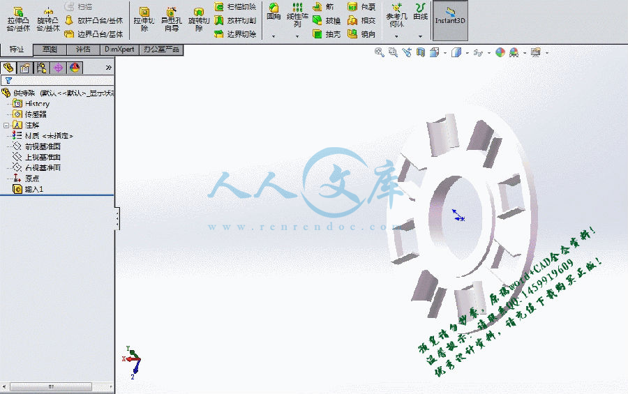
锥轮.dwg
锥轮.dwg

Koop-B型钢球式无级变速器结构设计【优秀】【带UG或SolidEdge三维】【word+7张CAD图纸全套】【毕设】

收藏

资源目录
跳过导航链接。
Koop-B型钢球式无级变速器结构设计【优秀】【带UG或SolidEdge三维】【word+7张CAD图纸全套】【毕设】.rar
锥轮.dwg---(点击预览)
鉴定意见.doc---(点击预览)
轴.dwg---(点击预览)
评阅表.doc---(点击预览)
装配.dwg---(点击预览)
箱体边.dwg---(点击预览)
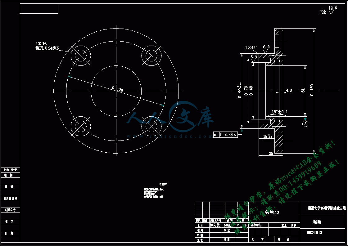
端盖.dwg---(点击预览)
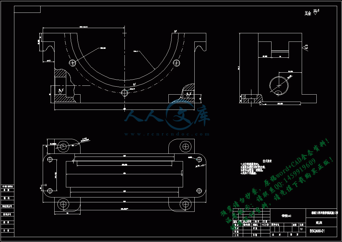
底座.dwg---(点击预览)
外文文献.pdf---(点击预览)
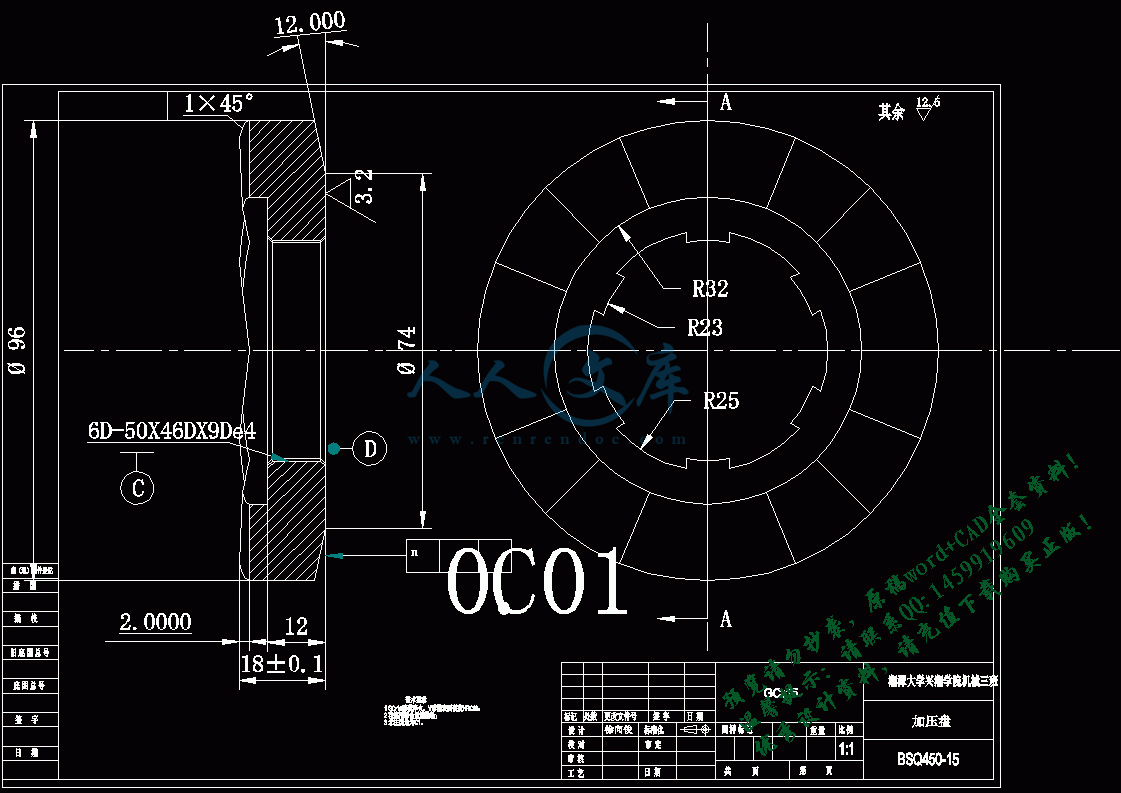
加压盘.dwg---(点击预览)
任务书.doc---(点击预览)
Koop-B型钢球式无级变速器结构设计正文.docx---(点击预览)
Solid Edge三维图
保持架.par
保持架2.par
加压滚珠.par
加压盘.dft
加压盘.par
压配式圆形油标.par
圆柱滚子轴承NF0000型.par
外环.par
平键A.par
平键B.par
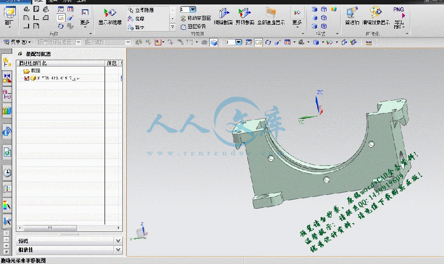
底座.dft
底座.par
油封.par
涡轮.par
涡轮边最终.par
涡轮边最终wunei.par
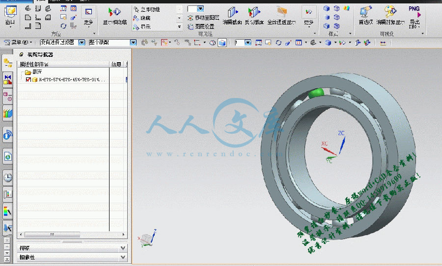
深沟球轴承6010.par
碟型唐璜.par
端盖.dft
端盖.par
箱体小边.par
箱体小边wunei.par
箱体边.dft
箱盖.par
蜗杆 所用毡圈油封.par
蜗杆 盖1.par
蜗杆.par
蜗杆加长盖.par
螺塞.par
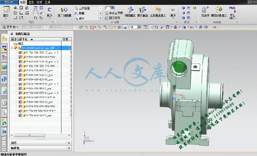
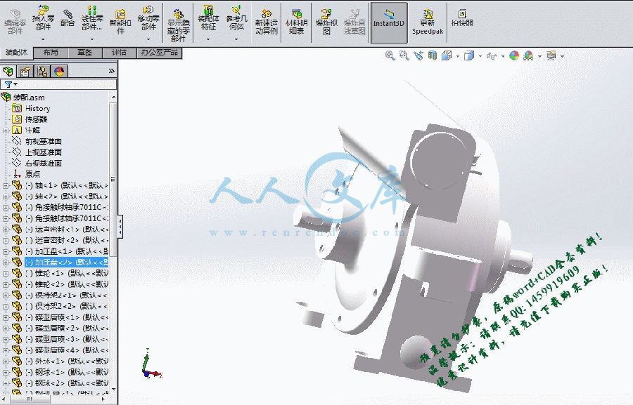
装配.asm
装配.cfg
装配.dft
角接触球轴承7011C.par
轴.dft
轴.par
迷宫密封.par
通气帽.par
钢球 轴.par
钢球.par
锥轮.dft
锥轮.par
压缩包内文档预览:
预览图
编号:303088    类型:共享资源    大小:6.73MB    格式:RAR    上传时间:2014-08-05 上传人:QQ14****9609 IP属地:陕西
45
积分
关 键 词:
钢球式 无级变速器 结构设计
资源描述:

Koop-B型钢球式无级变速器结构设计【优秀】【带UG或SolidEdge三维】【word+7张CAD图纸全套】【毕业设计】

【带任务书+鉴定意见+评阅表+外文翻译】【23页@正文9228字】【详情如下】【需要咨询购买全套设计请加QQ1459919609】.bat

Koop-B型钢球式无级变速器结构设计正文.docx

UG及SW三维

任务书.doc

加压盘.dwg

外文文献.pdf

底座.dwg

端盖.dwg

箱体边.dwg

装配.dwg

评阅表.doc

轴.dwg

鉴定意见.doc

锥轮.dwg

任务书

论文(设计)题目:    Koop-B型钢球式无级变速器结构设计                            


学号:   2010963034      姓名:    徐向俊     专业: 机械设计制造及其自动化                        

指导教师:          邱爱红                   系主任:     刘柏希                      

一、主要内容及基本要求

     1、以钢球、加压盘为传动件,设计一种机械摩擦式无级变速器;                                                                                

     2、输入功率P=5kw,输入转速n=1500rpm,调速范围R=10;                                                                              

     3、以UG或SolidEdge三维CAD软件为平台,建立整机的数字化模型;                                                                                

     4、完成A0#装配图纸1张,零件图总量不少于A0#图纸1张;                                                                                

     5、设计说明书一份;                                                                                

     6、英文文献一份。                                                                                

二、重点研究的问题

      1、钢球式无级变速器原理及其结构;                                                                                  

      2、变速原理的传动结构的实现。                                                                                  

三、进度安排

序号各阶段完成的内容完成时间

1熟悉课题及基础资料第1周

2调研及收集资料第2周

3方案设计与讨论第3~4周

4无级变速器各零件三维模型设计第5~8周

5无级变速器总装配图设计第9周

6无级变速器工程图设计第10周

7撰写说明书第11周

8英文文献翻译,答辩第12周

四、应收集的资料及主要参考文献

      [1] 周有强. 机械无级变速器[M]. 成都:机械工业出版社,2001.                

      [2] 阮忠唐.机械无级变速器设计与选用指南[M].北京:化学工业出版社,1999.                                                                      

      [3]  濮良贵,继名刚,机械设计[M].第7版.北京:高等教育出版社,2001                                                                    

目  录

摘要

Abstract

第一章 引言………………………………………………………………(1)

1.1机械无级变速的发展概况…………………………………………………(1)

1.2机械无级变速器的特征及应用……………………………………………(1)

1.3国内机械无级变速器的研究现状…………………………………………(2)

1.4钢球外锥式无级变速器简介………………………………………………(3)

1.5毕业论文设计内容及要求…………………………………………………(4)

第二章 主要零件的计算与设计…………………………………………(5)

2.1   钢球与主、从动锥轮的计算与设计………………………………………(5)

   2.2   加压盘的计算与设计………………………………………………………(8)

   2.3   调速齿轮上变速曲线槽的计算与设计……………………………………(9)

   2.4   输入、输出轴的计算与设计………………………………………………(10)

   2.5   输入、输出轴上轴承的计算与设计………………………………………(11)

   2.6   输入、输出轴上端盖的计算与设计………………………………………(11)

   2.7   调速机构的计算与设计……………………………………………………(11)

2.8   无级变速器的装配…………………………………………………………(13)

第三章 主要零件的校核…………………………………………………(14)

3.1   输入、输出轴的校核………………………………………………………(14)

3.2   轴承的校核…………………………………………………………………(16)

总结…………………………………………………………………………(18)

参考文献……………………………………………………………………(19)

钢球锥轮式无级变速器的设计

摘要:机械无级变速器能够适应不断变化的工艺要求,工艺开发和机械化的一般驱动器提高了设备的机械性能和自动化。本文描述的机械摩擦无级变速器,设计计算的方法,材料和润滑等的知识的基本结构,以及作为该无级变速器设计的理论基础。

这种设计是通过改变球的半径来实现球锥轮无级变速器的输出轴速度的连续变化用作中间球锥形轮驱动部件,工作。本文分析了主,从动轮,球和外工程和在传输过程中的传力之间的关系;实际CVT球锥轮设计公式的详细推导;和选择用于计算具体的设计参数的设计;绘制的零件图计算出的CVT球锥轮装配图和主传动组件,此传输技术的结构和要求的其它方面表现更清晰。

该无级变速器具有良好的结构和性能上的优势,具有很强的实用价值,可作为大规模生产的无级变速器。其主要特点是:1、调速范围宽; 2、良好的恒功率特性; 3、可以上升,减速,正,反转。4、光滑,耐冲击性强; 5、输出功率较大; 6、寿命长; 7、速简单,可靠; 8、维护方便。

关键词:无级变速器、摩擦式、钢球锥轮式、设计

Ball wheel cone design CVT

Abstract: Mechanical continuously variable transmission to adapt to changing process requirements , process development and the general drive to improve the mechanical properties of mechanization and automation equipment. Mechanical friction CVT described herein , design and calculation methods , materials and lubrication of the basic structure of knowledge , as well as the CVT design theories.

This design is continuously varied by changing the radius of the sphere to achieve the goals cone round CVT output shaft speed of the ball as an intermediate conical wheel drive parts, work . This paper analyzes the relationship between the driving and driven wheels , balls and external works and power transmission during transmission between ; detailed derivation of the actual CVT ball cone wheel design formulas ; and selection of design parameters used to calculate the specific design ; drawn parts diagram calculated CVT ball cone wheel assembly drawing and the main transmission components , other aspects of the performance of this transmission technology architecture and requirements clearer.

The CVT has a good structure and performance advantages , has a strong practical value , can be used as mass production CVT. Its main features are: wide speed range ; 2 good constant power characteristics ; 3 can rise , deceleration, positive and reverse . 4 .. smooth, high impact resistance ; larger 5 output power ; 6 , long life ; 7-speed is simple, reliable ; 8 , easy maintenance .

Keywords: CVT、Friction、Ball Cone Wheel、Design

第一章 引言

1.1 机械无级变速的发展概况

机械无级变速器是一个由变速传动机构、调速机构以及加压装置或输出机构三部分组成的一种传动装置,其主要功能特点是:在恒定的输入速度,输出轴速度可以在一定范围内实现连续变化,从而满足该机器或生产系统所需要操作过程中的各种不同的条件要求。

它配合减速器传动时具有显著作用,可进一步扩大变速范围与输出转矩,以提高产物的产率,满足产品改造,节约能源,实现机械化和自动化的整个系统的各方面的需要。因此CVT已经成为各个工业部门的公共传输部件,并且已被广泛使用。

机械无级变速器最初出现在19世纪70年代,但是当时受材质与工艺的条件限制,发展十分缓慢。直到20世纪70年代以后,一方面是与冶炼,热处理,精密加工及数控机床和牵引传动理论和油的产生和发展,解决CVT的研发和生产的限制因素;另一方面,随着生产过程的机械化,自动化和提高性能所需的机械的工作需要大量使用CVT的。因此,在这种情况下,机械无级变速器获得了快速而广泛的发展。主要开发和生产的国家有日本,德国,意大利,美国和俄罗斯等。产品有摩擦式、链式、带式及脉动式四大类约30多种不同的结构类型。输入功率一般为N=(0.09-30)千瓦,个别类型可达到N=(150-175)KW ,输入转速一般是n1=(750、1500、3000)转/分;输出转速可以是正,反转,增速或者减速,最小速率可以降低到零。 80年代以来,机械无级变速趋势是向美国,日本等国家进行用于汽车高速,高效,高扭矩的CVT进行研发 。

1.2 机械无级变速器的特征及应用

机械无级变速器是一种传动装置,其功能主要特点是:在恒定的输入速度下,输出轴速度可以在一定范围内连续变化来实现,以满足各种操作过程中不同的应用要求的机器或生产系统;其主要结构特征是:需要由可变速传动机构,调速机构和加压装置或输出装置由三个部分组成。

机械无级变速器的适用范围广,有在驱动功率保持不变时,由于工作阻力的变化,需要调整驱动转矩的速度以产生适当的驱动力矩者(例如,化工行业中的搅拌机械,即需要随着搅拌物料的粘度、阻力增大而能相应减慢搅拌速度);还有需要根据情况进行调整所需的速度者(如起重运输机械要求随物料及运行区段的变化而能相应改变或提升运行速度,食品机械中的烤干机或制药机械要求随着温度变化而调节转移速度);有为了获得恒定的运行速度或张力需要调节速度者(如需要切割导线截面切割加工时保持恒定的速度,电气机械络筒机需要保持一个恒定的卷绕速度,纺织机械,轻工机械浆纱机膜机都必须调整速度,以保证恒张力等);有在整个系统中为适应各种条件,需要协调各种工况、工位、工序或单元的不同要求,并具有自动速度控制者(如生产各种半自动或自动操作或流水线操作);有为了改变所要求的速度去探索最佳效果者(如试验机械或者离心机需要调速,以获得最佳的分离);有为了节能减排而需进行调速者(如风机,水泵等);此外,根据各种规律的或不规律的变化,进行自动调整速度或实现自动或程序控制等。

总之,采用无级变速器,特别是配合减速传动时,进一步扩大其转速范围和输出转矩,能够更好地适应于提高产品的产量和质量,以满足变换的最佳性能所需的各种条件,可以看出对产品的需求,节约能源,机械化和自动化的整个系统的所有方面都具有显著作用。因此,CVT已经成为传输的基本常见的形式,在纺织,轻工,食品,包装,化工,机床,电机,材料处理采矿和冶金,工程,农业,国防和测试等各类机械使用。

1.3国内机械无级变速器的研究现状

国内机械无级变速器基本上是围绕20世纪60年代开始到80年代中期,随着大量引进国外先进设备,工业生产和现代自动化流水线的快速发展,为各类机械无级变速器的专业厂家需求显著增加启动建设和规模化生产,一些大学已经开展了研究工作在外地。经过十多年的发展,现在,从机械式无级变速器的研发,生产,以情报信息的各个方面在国内同行业组成了一个较完整的体系,一个新兴的行业,在机械领域的发展。

目前,国内生产的机械式无级变速器的大多是模仿国外产品,主要产品类型:

   (1)摩擦式无级变速器:

1、行星锥盘式(DISCO型);

2、行星环锥式(RX型);

3、锥盘环盘式(干式、湿式);

4、多盘式(Bier型)等。

(2)齿链式无级变速器:

1、滑片链式;

2、滚柱链式;

3、链式卷绕式。

(3)带式无级变速器:

1、普通V带;

2、宽V带;

(4)脉动式无级变速器:

1、三相并列连杆式;

2、四相并开连杆式。

其中行星锥无级变速器高度灵活的光盘,结构和工艺相对简单,可靠,综合性能好,尤其是需要适应各种生产线,使用最广泛,产量最大,其年度账目机械50%超过无级变速器的总输出。输入功率为广大的CVT产品(0.18-7.5)千瓦,少数种类可以达到(22?30)千瓦左右。经过前一阶段通过实践,掌握本领域近几年,国内发展机械无级变速器的生产有一个新的发展趋势,主要是

(1)基础上的“恒功率行星摩擦式无级变速机”和“非物理心轴行星齿轮无级变速器”的创新和发展的原盘无级变速行星锥原有产品的创新和改进,后者的传动比由5个增至6至20个或更多,输出扭矩也增加了一倍多,等优良性能,还有一系列的产品。

(2)与CVT无级变速器汽车的研究和开发是一种高科技产品,目前已开通了金属带式无级变速器,经过测试,现在准备进行工业化生产;其中依靠关键部件“金属条”还将自己生产的进口。此外,新的汽车也被用在CVT和复合带进行讨论。

(3)开发新类型的创新的(汽车和通用)无级变速器近年来取得了创新性的无级变速器,其中无级变速器的特性主要是①无摩擦式传动,大多要链接脉动无级变速器的驱动器或采取的主链驱动; ②实现高功率,恒功率或速度要求; ③力求结构简单,紧凑,并获得优异的性能。这个计划,已经多年研究试验,在不久的将来,可能会见效。

上述情况可以解释,从过去国内的发展无级变速器模拟阶段和生产进入创新阶段,由低功耗的发展,大功率,高科技发展的总体技术方向,所以在未来可能会有一些新的一代机械无级变速器的优异性能。

随着电力电子技术的发展,自80年代以来,许多出现由交流电机调速方式进行。它作为一种先进的变速器,驱动器控制器及其获得机械无级变速器的迅速发展和应用衍生品产生了一定的影响。它的主要优点是速度快,性能好,规模大,效率高,良好的自我控制,很宽的功率范围。近年来,一种新型开关磁阻电机(Switched Reluctance Drive - SRD)的出现,以进一步提高性能;然而,缺点在于,它们都小于电机的额定速度,只在低转速的效率比低并且足够稳定,从过载性能较差等的恒定转矩特性。

上述功率调速相比,机械无级变速器的特性主要是:机械性能与恒功率,转速稳定,可靠,传动效率高,结构简单,维修方便,而且种类很多,范围广泛的应用。因此,在未来的发展,仍具有广阔的前景。

参考文献

[1] 周有强. 机械无级变速器[M]. 成都:机械工业出版社,2001.                

[2] 阮忠唐.机械无级变速器设计与选用指南[M].北京:化学工业出版社,1999.                                                                      

[3] 濮良贵,继名刚,机械设计[M].第7版.北京:高等教育出版社,2001  

[4] 赵又红,周知进,机械设计/机械设计基础课程设计指导.中南大学出版社,2012

[5] 苏旭平,工程材料[M].湘潭大学出版社,2011

[6] 成大先,机械设计文献[6][M],北京:化学工业出版社,2001

[7] 濮良贵,纪明刚,机械设计[M],北京:高等教育出版社,1996.11

内容简介:
湘潭大学兴湘学院毕业设计说明书题 目: Koop-B型钢球式无级变速器结构设计专 业: 机械设计制造及其自动化 学 号: 2010963034 姓 名: 徐向俊 指导教师: 邱爱红 完成日期: 2014年5月21日 湘潭大学兴湘学院毕业论文(设计)任务书论文(设计)题目: Koop-B型钢球式无级变速器结构设计 学号: 2010963034 姓名: 徐向俊 专业: 机械设计制造及其自动化 指导教师: 邱爱红 系主任: 刘柏希 一、主要内容及基本要求 1、以钢球、加压盘为传动件,设计一种机械摩擦式无级变速器; 2、输入功率P=5kw,输入转速n=1500rpm,调速范围R=10; 3、以UG或SolidEdge三维CAD软件为平台,建立整机的数字化模型; 4、完成A0#装配图纸1张,零件图总量不少于A0#图纸1张; 5、设计说明书一份; 6、英文文献一份。 二、重点研究的问题 1、钢球式无级变速器原理及其结构; 2、变速原理的传动结构的实现。 三、进度安排序号各阶段完成的内容完成时间1熟悉课题及基础资料第1周2调研及收集资料第2周3方案设计与讨论第34周4无级变速器各零件三维模型设计第58周5无级变速器总装配图设计第9周6无级变速器工程图设计第10周7撰写说明书第11周8英文文献翻译,答辩第12周四、应收集的资料及主要参考文献 1 周有强. 机械无级变速器M. 成都:机械工业出版社,2001. 2 阮忠唐.机械无级变速器设计与选用指南M.北京:化学工业出版社,1999. 3 濮良贵,继名刚,机械设计M.第7版.北京:高等教育出版社,2001 湘潭大学兴湘学院毕业论文(设计)评阅表学号 2010963034 姓名 徐向俊 专业 机械设计制造及其自动化 毕业论文(设计)题目: Koop-B型钢球式无级变速器结构设计 评价项目评 价 内 容选题1.是否符合培养目标,体现学科、专业特点和教学计划的基本要求,达到综合训练的目的;2.难度、份量是否适当;3.是否与生产、科研、社会等实际相结合。能力1.是否有查阅文献、综合归纳资料的能力;2.是否有综合运用知识的能力;3.是否具备研究方案的设计能力、研究方法和手段的运用能力;4.是否具备一定的外文与计算机应用能力;5.工科是否有经济分析能力。论文(设计)质量1.立论是否正确,论述是否充分,结构是否严谨合理;实验是否正确,设计、计算、分析处理是否科学;技术用语是否准确,符号是否统一,图表图纸是否完备、整洁、正确,引文是否规范;2.文字是否通顺,有无观点提炼,综合概括能力如何;3.有无理论价值或实际应用价值,有无创新之处。综合评 价 论文选题综合性强,基本符合机械专业培养目标和要求,题目难度适中,与工业生产实际结合较为紧密。论文作者具有较强的查阅文献和综合归纳资料的能力,综合应用本学科所学只是能力较强。 论文理论基本正确,论述比较充分,整体结构尚可;设计计算比较科学,技术用语比较准确,引文比较规范。文字通顺,综合概括能力较强;论文具有一定的参考价值。 同意进行答辩评阅人: 2010年5月 日湘潭大学兴湘学院毕业论文(设计)鉴定意见学号:2010963034姓名徐向俊专业:机械设计制造及其自动化毕业论文(设计说明书)21 页 图表 7 张论文(设计)题目:Koop-B型钢球式无级变速器结构设计内容提要:Koop-B型钢球式无级变速器,动力由输入轴输入,经自动加压装置带动主动轮同速转动,再经一组钢球利用牵引力驱动外环和从动轮,最后经锥轮、自动加压装置驱动输出轴将动力输出。传动钢球的支撑轴的两端嵌装在端盖的径向弧形导槽内,轴通过调速蜗轮上的凸轮槽;调速时,通过蜗杆使蜗轮转动,由于凸轮槽的作用,使钢球轴心线的倾角发生变化,导致钢球与主、从动轮的工作直径改变,输出轴的转速得到调节,从而达到变速的作用。在设计、制造与安装时,一组钢球直径要一致、球孔轴线与直径要一致、端盖经向圆弧槽的等分性及其圆弧中心和球心要一致、调速蜗轮上凸轮槽的等分性,以及钢球、锥轮、加压盘的制造精度和表面粗糙度应注意。在设计时根据已知数据算出钢球直径,钢球的轴心线倾斜角度范围,钢球中心圆直径,钢球倾隙,外环尺寸。随后加压盘的计算与设计,以及调速齿轮上变速曲线槽的计算与设计,输入、输出轴的设计与计算,调速机构的计算与设计,无级变速器的装配,最后是主要零件的校核,符合设计要求后,根据所算出的数据利用soild edge st4软件画出三维零件图、装配图,完成整个毕业设计。指导教师评语该生在本次毕业设计中表现出基础知识较扎实、独立工作能力较强。计算机操作较熟练。劳动纪律性较强,工作较认真。能如期完成设计任务,设计方案基本正确,图面质量较好,结构尚合理。设计说明书撰写较认真,具有一定的专业英文文献阅读与翻译能力。同意其参加答辩。建议成绩评定为:指导教师:年 月 日答辩简要情况及评语答辩小组组长:年 月 日答辩委员会意见答辩委员会主任:年 月 日目 录摘要Abstract第一章 引言(1)1.1 机械无级变速的发展概况(1)1.2 机械无级变速器的特征及应用(1)1.3 国内机械无级变速器的研究现状(2)1.4 钢球外锥式无级变速器简介(3)1.5 毕业论文设计内容及要求(4)第二章 主要零件的计算与设计(5)2.1 钢球与主、从动锥轮的计算与设计(5) 2.2 加压盘的计算与设计(8) 2.3 调速齿轮上变速曲线槽的计算与设计(9) 2.4 输入、输出轴的计算与设计(10) 2.5 输入、输出轴上轴承的计算与设计(11) 2.6 输入、输出轴上端盖的计算与设计(11) 2.7 调速机构的计算与设计(11)2.8 无级变速器的装配(13)第三章 主要零件的校核(14)3.1 输入、输出轴的校核(14)3.2 轴承的校核(16)总结(18)参考文献(19)钢球锥轮式无级变速器的设计摘要:机械无级变速器能够适应不断变化的工艺要求,工艺开发和机械化的一般驱动器提高了设备的机械性能和自动化。本文描述的机械摩擦无级变速器,设计计算的方法,材料和润滑等的知识的基本结构,以及作为该无级变速器设计的理论基础。这种设计是通过改变球的半径来实现球锥轮无级变速器的输出轴速度的连续变化用作中间球锥形轮驱动部件,工作。本文分析了主,从动轮,球和外工程和在传输过程中的传力之间的关系;实际CVT球锥轮设计公式的详细推导;和选择用于计算具体的设计参数的设计;绘制的零件图计算出的CVT球锥轮装配图和主传动组件,此传输技术的结构和要求的其它方面表现更清晰。该无级变速器具有良好的结构和性能上的优势,具有很强的实用价值,可作为大规模生产的无级变速器。其主要特点是:1、调速范围宽; 2、良好的恒功率特性; 3、可以上升,减速,正,反转。4、光滑,耐冲击性强; 5、输出功率较大; 6、寿命长; 7、速简单,可靠; 8、维护方便。关键词:无级变速器、摩擦式、钢球锥轮式、设计Ball wheel cone design CVTAbstract: Mechanical continuously variable transmission to adapt to changing process requirements , process development and the general drive to improve the mechanical properties of mechanization and automation equipment. Mechanical friction CVT described herein , design and calculation methods , materials and lubrication of the basic structure of knowledge , as well as the CVT design theories.This design is continuously varied by changing the radius of the sphere to achieve the goals cone round CVT output shaft speed of the ball as an intermediate conical wheel drive parts, work . This paper analyzes the relationship between the driving and driven wheels , balls and external works and power transmission during transmission between ; detailed derivation of the actual CVT ball cone wheel design formulas ; and selection of design parameters used to calculate the specific design ; drawn parts diagram calculated CVT ball cone wheel assembly drawing and the main transmission components , other aspects of the performance of this transmission technology architecture and requirements clearer.The CVT has a good structure and performance advantages , has a strong practical value , can be used as mass production CVT. Its main features are: wide speed range ; 2 good constant power characteristics ; 3 can rise , deceleration, positive and reverse . 4 . smooth, high impact resistance ; larger 5 output power ; 6 , long life ; 7-speed is simple, reliable ; 8 , easy maintenance .Keywords: CVT、Friction、Ball Cone Wheel、Design第一章 引言1.1 机械无级变速的发展概况机械无级变速器是一个由变速传动机构、调速机构以及加压装置或输出机构三部分组成的一种传动装置,其主要功能特点是:在恒定的输入速度,输出轴速度可以在一定范围内实现连续变化,从而满足该机器或生产系统所需要操作过程中的各种不同的条件要求。它配合减速器传动时具有显著作用,可进一步扩大变速范围与输出转矩,以提高产物的产率,满足产品改造,节约能源,实现机械化和自动化的整个系统的各方面的需要。因此CVT已经成为各个工业部门的公共传输部件,并且已被广泛使用。机械无级变速器最初出现在19世纪70年代,但是当时受材质与工艺的条件限制,发展十分缓慢。直到20世纪70年代以后,一方面是与冶炼,热处理,精密加工及数控机床和牵引传动理论和油的产生和发展,解决CVT的研发和生产的限制因素;另一方面,随着生产过程的机械化,自动化和提高性能所需的机械的工作需要大量使用CVT的。因此,在这种情况下,机械无级变速器获得了快速而广泛的发展。主要开发和生产的国家有日本,德国,意大利,美国和俄罗斯等。产品有摩擦式、链式、带式及脉动式四大类约30多种不同的结构类型。输入功率一般为N=(0.09-30)千瓦,个别类型可达到N=(150-175)KW ,输入转速一般是n1=(750、1500、3000)转/分;输出转速可以是正,反转,增速或者减速,最小速率可以降低到零。 80年代以来,机械无级变速趋势是向美国,日本等国家进行用于汽车高速,高效,高扭矩的CVT进行研发 。1.2 机械无级变速器的特征及应用机械无级变速器是一种传动装置,其功能主要特点是:在恒定的输入速度下,输出轴速度可以在一定范围内连续变化来实现,以满足各种操作过程中不同的应用要求的机器或生产系统;其主要结构特征是:需要由可变速传动机构,调速机构和加压装置或输出装置由三个部分组成。机械无级变速器的适用范围广,有在驱动功率保持不变时,由于工作阻力的变化,需要调整驱动转矩的速度以产生适当的驱动力矩者(例如,化工行业中的搅拌机械,即需要随着搅拌物料的粘度、阻力增大而能相应减慢搅拌速度);还有需要根据情况进行调整所需的速度者(如起重运输机械要求随物料及运行区段的变化而能相应改变或提升运行速度,食品机械中的烤干机或制药机械要求随着温度变化而调节转移速度);有为了获得恒定的运行速度或张力需要调节速度者(如需要切割导线截面切割加工时保持恒定的速度,电气机械络筒机需要保持一个恒定的卷绕速度,纺织机械,轻工机械浆纱机膜机都必须调整速度,以保证恒张力等);有在整个系统中为适应各种条件,需要协调各种工况、工位、工序或单元的不同要求,并具有自动速度控制者(如生产各种半自动或自动操作或流水线操作);有为了改变所要求的速度去探索最佳效果者(如试验机械或者离心机需要调速,以获得最佳的分离);有为了节能减排而需进行调速者(如风机,水泵等);此外,根据各种规律的或不规律的变化,进行自动调整速度或实现自动或程序控制等。总之,采用无级变速器,特别是配合减速传动时,进一步扩大其转速范围和输出转矩,能够更好地适应于提高产品的产量和质量,以满足变换的最佳性能所需的各种条件,可以看出对产品的需求,节约能源,机械化和自动化的整个系统的所有方面都具有显著作用。因此,CVT已经成为传输的基本常见的形式,在纺织,轻工,食品,包装,化工,机床,电机,材料处理采矿和冶金,工程,农业,国防和测试等各类机械使用。1.3 国内机械无级变速器的研究现状国内机械无级变速器基本上是围绕20世纪60年代开始到80年代中期,随着大量引进国外先进设备,工业生产和现代自动化流水线的快速发展,为各类机械无级变速器的专业厂家需求显著增加启动建设和规模化生产,一些大学已经开展了研究工作在外地。经过十多年的发展,现在,从机械式无级变速器的研发,生产,以情报信息的各个方面在国内同行业组成了一个较完整的体系,一个新兴的行业,在机械领域的发展。 目前,国内生产的机械式无级变速器的大多是模仿国外产品,主要产品类型: (1)摩擦式无级变速器:1、行星锥盘式(DISCO型);2、行星环锥式(RX型);3、锥盘环盘式(干式、湿式);4、多盘式(Bier型)等。(2)齿链式无级变速器:1、滑片链式;2、滚柱链式;3、链式卷绕式。(3)带式无级变速器:1、普通V带;2、宽V带;(4)脉动式无级变速器:1、三相并列连杆式;2、四相并开连杆式。其中行星锥无级变速器高度灵活的光盘,结构和工艺相对简单,可靠,综合性能好,尤其是需要适应各种生产线,使用最广泛,产量最大,其年度账目机械50超过无级变速器的总输出。输入功率为广大的CVT产品(0.18-7.5)千瓦,少数种类可以达到(2230)千瓦左右。经过前一阶段通过实践,掌握本领域近几年,国内发展机械无级变速器的生产有一个新的发展趋势,主要是(1)基础上的“恒功率行星摩擦式无级变速机”和“非物理心轴行星齿轮无级变速器”的创新和发展的原盘无级变速行星锥原有产品的创新和改进,后者的传动比由5个增至6至20个或更多,输出扭矩也增加了一倍多,等优良性能,还有一系列的产品。(2)与CVT无级变速器汽车的研究和开发是一种高科技产品,目前已开通了金属带式无级变速器,经过测试,现在准备进行工业化生产;其中依靠关键部件“金属条”还将自己生产的进口。此外,新的汽车也被用在CVT和复合带进行讨论。(3)开发新类型的创新的(汽车和通用)无级变速器近年来取得了创新性的无级变速器,其中无级变速器的特性主要是无摩擦式传动,大多要链接脉动无级变速器的驱动器或采取的主链驱动; 实现高功率,恒功率或速度要求; 力求结构简单,紧凑,并获得优异的性能。这个计划,已经多年研究试验,在不久的将来,可能会见效。上述情况可以解释,从过去国内的发展无级变速器模拟阶段和生产进入创新阶段,由低功耗的发展,大功率,高科技发展的总体技术方向,所以在未来可能会有一些新的一代机械无级变速器的优异性能。随着电力电子技术的发展,自80年代以来,许多出现由交流电机调速方式进行。它作为一种先进的变速器,驱动器控制器及其获得机械无级变速器的迅速发展和应用衍生品产生了一定的影响。它的主要优点是速度快,性能好,规模大,效率高,良好的自我控制,很宽的功率范围。近年来,一种新型开关磁阻电机(Switched Reluctance Drive - SRD)的出现,以进一步提高性能;然而,缺点在于,它们都小于电机的额定速度,只在低转速的效率比低并且足够稳定,从过载性能较差等的恒定转矩特性。上述功率调速相比,机械无级变速器的特性主要是:机械性能与恒功率,转速稳定,可靠,传动效率高,结构简单,维修方便,而且种类很多,范围广泛的应用。因此,在未来的发展,仍具有广阔的前景。1.4 钢球外锥无级变速器简介钢球外锥式机械无级变速器的结构如图1-1所示。动力由轴1输入,通过自动加压装置2,带动主动轮3同速转动,经一组(38个)钢球4利用摩擦力驱动外环7和从动锥轮9;再经锥轮轮9、自动加压装置10驱动输出轴11,最后将动力输出。传动钢球的支承轴8的两端嵌装在壳体两端盖12和l3的径间弧形导槽内,并穿过调速蜗轮5的曲线槽;调速时,通过蜗杆6使蜗轮5转动。由于曲线槽(相当于一个控制凸轮)的作用,使钢球轴心线的倾斜角发生变化,导致钢球与两锥轮的工作半径改变,输出轴的转速便得到调节。其动力范围为:nR=9,Imax=1/Imin,P11KW,4%,0.800.92,应用甚广。从动调速齿轮5的端面分布一组曲线槽,曲线槽数目与钢球数相同。曲线槽可用阿基米德螺旋线,也可用圆弧。当转动主动齿轮6使从动齿轮5转动时,从动齿轮的曲线槽迫使传动钢球轴8绕钢球4的轴心线摆动,传动轮3以及从动轮9与钢球4的接触半径发生变化,实现无级调速。 图1-1 钢球外锥式无级变速器的结构1、11-输入、输出轴;2、10-加压装置;3、9-主、从动锥轮;4-传动钢球;5-调速涡轮6-调速蜗杆;7-外环;8-传动钢球轴;12、13-端盖1.5 毕业论文设计内容及要求毕业设计内容:钢球机械无级变速器结构的设计:选择钢球外锥式机械无级变速器,对其进行机构设计与;对关键部件进行强度校核和寿命校核。设计要求:输入功率P=5kw,输入转速n=1500rpm.调速范围R=10;结构设计时应使制造成本尽可能低;安装拆卸要方便;外观要匀称,美观;调速要灵活,调速过程中不能出现卡死现象,能实现动态无级调速;关键部件满足强度和寿命要求;画零件图和装配图。 第二章 主要零件的计算与设计2.1 钢球与主、从动锥轮的计算与设计 确定传动件的主要尺寸1、 选材:钢球、锥轮、外环及加压盘均用GCr15,表面硬度HRC61,摩擦系数=0.04,许用应力,属于点接触,查文献2表2-5知传动件=22002500MPa,压力元件=44005000MPa。2、 预选参数:锥轮锥顶半角=45,传动钢球个数为Z=6,加压钢球数m=8,锥轮与钢球= =1.5,=1.25,=0.8。图2-1 钢球外锥式机械无级变速器设计简图3、 运动参数的计算 各尺寸对应图2-1标注尺寸传动比 imax=1500750=2 imin=250750=0.3333钢球支撑轴承的极限转角: 4、 计算确定传动钢球的直径dq 由查文献2表2-3,得,代入公式 cm 表2-1 按传递功率P1选取钢球直径dq的参考值 mm根据表2-1中的数据,圆整取锥轮直径mm圆取整 则 演算接触应力 在许用接触应力范围之内,故可用。5、 计算尺寸钢球中心圆直径 钢球侧隙 外环内径 外环轴向弧半径R 取 R=7.5cm锥轮工作圆之间的轴向距离B 2.2 加压盘的计算与设计图2-2 钢球V型槽式加压装置1、 钢球式自动加压装置如图2-2,它由加压盘,加压钢球,保持架,调整垫圈,碟形弹簧和摩擦轮与加压盘相对端面上各有的几条均匀分布的V型槽。每个槽内有一个钢球,中间以保持架保持钢球的相对位置。摩擦轮与加压盘之间还有预压蝶形弹簧并衬以调整垫圈。改变调整垫圈的厚度,即可调整弹簧的变形量及预压力。2、 加压装置的主要参数确定加压盘作用直径 其中为锥轮直径。加压盘V形槽倾角 取其中为锥轮锥顶半角,为锥轮与钢球的摩擦系数。加压钢球按经验公式取 所以轴向压紧力法向压紧力 故接触强度不足改用腰鼓形滚子8个,取滚子轴向截面圆弧半径,横向中间截面半径。曲率系数 由文献2表2-3,按,得带入 =23397.958kgf/cm2 工作应力在许用范围内,故可用。2.3 调速齿轮上变速曲线槽的计算与设计 图2-3 调速涡轮的槽型曲线如图2-3,整个调速过程通常在涡轮转角的范围内完成,多数取。槽型曲线可以为阿基米德螺旋线,也可以用圆弧代替。此方案选用圆弧代替,变速槽中心线必须通过A,B,C三点,他们的级坐标(以O点为级点)分别为:A: , B: , C: , 定出A、B、C三点,然后采用画图做出弧形槽,槽宽为10mm。2.4 输入、输出轴的计算与设计 为了防止当轴部分或周向相对运动轴部件除了游泳或空转的要求,必须在轴向和周向定位的,以确保其精确的工作位置,从而使该程序使用定位轴肩,套筒上的轴向力,轴圈,轴承端盖和螺母来保证。1、 初步确定轴的最小轴径先按公式初步估算轴的最小直径。选取轴的材料为45号钢,调制处理。选取,于是得出: 输出轴的最小直径为与锥轮连接处,考虑到此处锥轮与轴是过渡配合,且锥轮工作直径为155mm,为了保证锥轮与轴配合有良好的对中性,采用锥轮标准的推荐直径为40mm。 图2-4 输入、输出轴各轴段分布图2、根据轴向定位的要求确定轴的各段直径和长度如图2-4,I轴段安装锥轮和加压盘保持架,保证和轴配合的毂孔长度,取,;II段轴安装加压盘的一侧以及轴承,加压盘用花键移动实现对锥轮加压,取花键 GB/T1144-87,轴承同时受到径向力和轴向力作用,初步选择滚动轴承加上退刀槽,取,;III轴段对轴II和轴IV上的轴承内圈起到定位作用,取,;IV轴段做为轴承座安装滚动轴承,因为受轴向力大使用角接触球轴承,取,;V轴段根据轴承端盖的装拆和便于对轴承添加润滑剂的要求,采用迷宫式密封,根据标准取,;轴VI段安装V带,采用推荐直径,。以上初步确定了各轴段直径与长度,因为主、从动锥轮一致,轴上零件分布也一样,同时为了节约成本和工艺,选择主、从动轴完全一致。2.5 输入、输出轴上轴承的计算与设计 轴承是标准件,只需要根据参数选择合适的轴承就可以了,主、从动轴II段上因为轴承受到轴向力和径向力的作用,因此选择深沟球轴承6010GB/T276-94;轴IV段轴承为限制轴向右的轴向移动,所以选择角接触球轴承7011GB/T292-94;两个轴承的基本额定动载荷都大于10KN,因此角接触球轴承采用正装可满足使用要求。2.6 输入、输出轴上端盖的计算与设计端盖的宽度有变速器外形和轴承的结构来决定的,使其适合拆装和便于对轴承添加润滑脂,且左右两个端盖相同。2.7 调速机构的计算与设计 调速操纵机构的作用:根据工作要求以手动或自动控制方式,改变滚动体(或脉动无级变速器的杆件)间的尺寸比例关系,来实现无级调速。同时通过速度表表盘上的指针直接指出任一调速位置时的输出速度(或传动比)。 根据变速器中传动机构和滚动体形状的不同,对应的调速机构也不同,但基本原理都是将其中某一个滚动体沿另一个(或几个)滚动体母线移动的方式来进行调速。 一般滚动体均是以直线或圆弧为母线的旋转体;因此,调速时使滚动体沿另一滚动体表面做相对运动的方式,只有直线移动和旋转(摆动)两种方式。这样可将调速机构分为下列两大类:(1) 通过使滚动体移动来改变工作半径的;主要用于两滚轮的母线均为直线的情况,且两轮的回转轴线平行或相交时,移动和方向是两轮的接触线方向。(2) 通过使滚轮轴线的偏转来改变工作半径的; 主要用于滚轮的母线为圆弧的情况钢球外锥式无级变速器是采用第二种调速类型,通过涡轮-凸轮组合机构,经涡轮转动再经槽凸轮而使钢球心轴绕其圆心转动,以实现钢球主、从动侧工作半径的改变。 调速涡轮在设计上应保证避免与其他零件发生干涉,同时采用单头蜗杆,以增加自锁性,避免自动变速而失稳。 根据整体设计,蜗杆传动的基本尺寸及参数匹配如表2-2、表2-3: 表2-2 蜗杆的基本尺寸模数mm轴向齿距mm分度圆直径mm头数直径系数mm齿顶圆直径mm齿根圆直径mm值分度圆柱导程角825.133380110.0009660.85120 表2-3 蜗轮蜗杆参数匹配中心距mm传动比模数(mm)蜗杆分度圆直径(mm)蜗杆头数涡轮齿数涡轮变位系数20041880141-0.5002.8 无级变速器的装配1、 变速器的装配1) 必须彻底的清洗所有的零件,并且用压缩空气吹干或者擦干净;2) 安装前,各轴承和键槽必须涂上齿轮油或者机械油;3) 装入轴承前,应使用铜棒在轴承四周均匀敲入;避免用手锤直接敲击轴承,防止轴承损伤;4) 在安装轴承端盖之前,壳体上的轴承孔与螺孔应涂上密封胶防止漏油;5) 每个紧固螺栓应该按规定锁紧;2、 变速器在装配中的调整1) 锥轮端面与涡轮之间的间隙,一般应为0.10-0.35mm;2) 轴的轴向间隙一般取0.10-0.40mm,可通过轴承盖内垫片的增减来调整;3) 检查调速情况和蜗杆传动的啮合情况,各档涡轮应该具备较好的自锁性,齿的啮合痕迹应该大于全齿工作面积的三分之一;第三章 主要零件的校核 本章主要是根据传动要求对无级变速器做一个整体的校核。钢球的强度校核在设计过程中已经符合要求,变速器的承载能力主要受加压装置及钢球与主、从动锥轮之间的接触强度的限制,同时在制造与安装过程中应保证一组钢球的直径的一致性。轴承采用标准件,由于蜗杆是用于调速,其轴承主要起支撑作用,受力时间短,故再此不做校核,对轴上轴承进行强度与寿命计算。3.1 轴的校核)判断危险截面截面B,IV,V只受扭矩的作用,虽然键槽、轴肩及过渡配合所引起的应力集中均将消弱轴的疲劳强度,但由于轴的最小直径是按扭转强度较为宽裕地确定的,所以截面B、IV,V均无需校核。 从应力集中对轴的疲劳强度的影响来看,截面IV和V处过盈配合引起的应力集中最严重;从受载的情况来看,截面C上受力最大。截面VI和VII显然更不必校核。键槽的应力集中系数比过盈配合的小,因而该轴只需校核截面C左右两侧即可。)截面C左侧抗弯截面系数 Nmm 抗扭矩截面系数 Nmm 截面C左侧的弯矩M为 Nmm 截面C左侧的扭矩为 Nmm 截面上的弯矩应力为 截面上的扭转切应力 轴的材料为45号钢,调质处理,由轴常用材料性能表查得:截面上由于退刀槽而形成的理论应力集中系数及按文献6中查取。因,经插值后可查得k 又由文献6可得轴的材料的敏性系数为故有应力集中系数 =1+0.821.26由文献6得尺寸系数;扭转尺寸系数。轴按磨削加工,由文献6得表面质量系数轴未经表面强化处理,即,按文献6得综合系数为 又由文献6得材料特性系数 0.2,取 0.1,取于是,计算安全系数Sca值,按公式则得 s=1.5故可知其安全。 3)截面C右侧同理可得 故该轴在截面IV右侧的强度也足够的。本题因无大的瞬时过载及严重的应力循环不对称性,故可略去静强度校核。因此,轴的设计校核结束。 3.2 轴承的校核输入、输出轴采用相同的设计,在此只要校核输出轴的轴承是否满足工程需要。1)求两轴承受到的径向载荷和将轴系部件受到的空间力系分解为铅垂面和水平面两个力系。其中:为通过另外加转矩而平移到指向轴线;亦应通过另加弯矩而平移到作用于轴线上。有受力分析可知: N N N N N N2)求两轴承的计算轴上力和对于6010C型轴承,按文献6,轴承派生轴向力,其中,e为判断系数,其值由的大小来确定,但是现在轴承轴向力未知,故先初取e=0.4,因此可估算 N N N N又得: 查文献6确定,,。3)求轴承当量动载荷,由文献6进行查表或差值计算得径向载荷系数和轴向载荷系数为:对轴承1 对轴承2 因为轴承运转中有中等冲击载荷,按文献6查得,取。则4) 验算轴承寿命因为,所以按轴承2的受力计算大小来验算综上所述可得,该设计符合工程要求。总结本科毕业设计历时两个半月,在这两个半月中,我能按照预期进度安排,按时按量的完成设计任务。设计初期,我复习了机械设计、材料力学、工程图学等知识,查阅了机械设计文献6、课程设计指导等规范。在设计中期,利用所学专业知识进行无级变速器结构和外观的设计。设计后期,主要进行三维图和工程图绘制。设计期间得到了邱老师的指导和帮助,在此深表谢意。毕业设计是对大学四年所学知识的综合应用,是理论联系实际的训练。通过毕业设计,我复习了以前在课堂上学习的专业知识,学习和体会到了机械设计的基本技能和思想。我深刻的认识到:想成为一名机械工程师,应该具备严谨的科学态度,本着机械产品以人为本的思想,力求做到安全、经济、实用、耐久、美观;设计过程中,应该严格按照机械设计文献6的要求,同时也要考虑各个零部件的尺寸配合。这就要求设计人员具备较高的综合素质,不仅要抓住机械产品设计的主要矛盾,同时也要考虑一些细节问题。 在毕业设计的过程中,我深刻认识到标准是设计的航标,必须多思考、多体会。在以后的学习和工作中,要不断加强对标准的学习和理解,只有这样,才不会出现错误。相互学习,注重交流。在设计过程中,我们遇到了很多问题,必须勤学好问,努力发挥集体的积级性和创造力,这样才能提高工作效率。 “养兵千日,用兵一时。”在毕业设计中,我为能用上四年所学而欣慰,同时我深深的感觉到了基础知识的重要性。专业课学习时,老是感觉所学知识与实际相差太远。这种急功近利的思想使自己对一些专业课的学习有所放松,在毕业设计的过程中,我深深的体会到了“书到用时方恨少”的含义。在以后的学习生活中切不可急于求成而忽略了夯实基础。“万丈高楼从地起”,切实做到理论联系实际,学以致用。毕业设计是本科教育非常重要的阶段,我初步掌握了机械设计的基础理论、方法、步骤。在以后的学习生活中,我将加强专业知识的学习。在此再次感谢在毕业设计中指导帮助我的老师和同学。 参考文献1 周有强. 机械无级变速器M. 成都:机械工业出版社,2001. 2 阮忠唐.机械无级变速器设计与选用指南M.北京:化学工业出版社,1999. 3 濮良贵,继名刚,机械设计M.第7版.北京:高等教育出版社,2001 4 赵又红,周知进,机械设计/机械设计基础课程设计指导.中南大学出版社,2012 5 苏旭平,工程材料M.湘潭大学出版社,20116 成大先,机械设计文献6M,北京:化学工业出版社,20017 濮良贵,纪明刚,机械设计M,北京:高等教育出版社,1996.11 任务书论文(设计)题目: Koop-B型钢球式无级变速器结构设计 学号: 2010963034 姓名: 徐向俊 专业: 机械设计制造及其自动化 指导教师: 邱爱红 系主任: 刘柏希 一、主要内容及基本要求 1、以钢球、加压盘为传动件,设计一种机械摩擦式无级变速器; 2、输入功率P=5kw,输入转速n=1500rpm,调速范围R=10; 3、以UG或SolidEdge三维CAD软件为平台,建立整机的数字化模型; 4、完成A0#装配图纸1张,零件图总量不少于A0#图纸1张; 5、设计说明书一份; 6、英文文献一份。 二、重点研究的问题 1、钢球式无级变速器原理及其结构; 2、变速原理的传动结构的实现。 三、进度安排序号各阶段完成的内容完成时间1熟悉课题及基础资料第1周2调研及收集资料第2周3方案设计与讨论第34周4无级变速器各零件三维模型设计第58周5无级变速器总装配图设计第9周6无级变速器工程图设计第10周7撰写说明书第11周8英文文献翻译,答辩第12周四、应收集的资料及主要参考文献 1 周有强. 机械无级变速器M. 成都:机械工业出版社,2001. 2 阮忠唐.机械无级变速器设计与选用指南M.北京:化学工业出版社,1999. 3 濮良贵,继名刚,机械设计M.第7版.北京:高等教育出版社,2001 附录附录 翻译原翻译原文及译文文及译文 Weld robot application present condition According to incompletely statistics, the whole world about has in the industrial robot of service nearly half of industrial robots is used for multiform weld to process realm, weld robot of application in mainly have two kinds of methods most widespreadly, then order Han and electricity Hu Han.What we says welding robot is in fact welding to produce realm to replace a welder to be engaged in the industrial robot of welding the task.These weld to have plenty of to design for being a certain to weld a way exclusively in the robot of, but majority ofly weld robot in fact is an in general use industrial robot to pack up a certain weld tool but constitute.In many task environments, a set robot even can complete include weld at inside of grasp a thing, porterage, install, weld, unload to anticipate etc. various tasks, robot can request according to the procedure with task property and automatically replace the tool on the robot wrist, the completion corresponds of task.Therefore, come up to say from a certain meaning, the development history of industrial robot is the development history that welds robot. Know to all, weld to process to request that welder have to have well-trained operation technical ability, abundant fulfillment experience, stability of weld level;It is still a kind of labor condition bad, many smoke and dust, hot the radiation is big, risk Gao of work.The emergence of the industrial robot makes people naturally thought of first the handicraft that replace a person with it welds and eases the welders labor strength, can also promise to weld quality and exaltation to weld an efficiency at the same time. However, weld again with other industry process process different, for example, electricity Hu Han process in, drive welder piece because of part heat melt with cool off creation transform, the Han sews of the track will therefore take place to change.Handicraft Han the experienced welder can sew position according to the actual Han observed by eyes adjustment Han in good time the position, carriage of the gun and run about of speed to adapt to the variety that the Han sews a track.However the robot want to adapt to this kind of variety, have to the position and status of gun that want tosee this kind of to change, then adopt homologous measure to adjust Han like person first, follow while carrying out to sew actually to the Han.Because the electricity Hu welds to have in process strong arc light, give or get an electric shock Hu noise, smoke and dust and Rong drop transition unsteady and causable Han silk short circuit, big electric current strong magnetic field etc. complicated environment factor of existence, the robot wants to examine and identifies a withdrawing of the signal characteristic needed for sewing Han and dont seem to be industrial the other in the manufacturing to process the examination of process so easily, therefore, welding the application of robot is to used for to give or get an electric shock the process of Hu Han in the beginning. Actually, industrial robot at welded the application of realm to produce on-line electric resistance to order a Han beginning from the car assemble at the earliest stage.The reason lies in the process that the electric resistance orders Han opposite more simple, control convenient, and not need Han to sew a track follow, to the accuracy of the robot and repeat the control of accuracy have lower request.Order the Han robot assembles to produce a great deal of on-line application to consumedly raise the rate of production that the car assemble welds and weld quality in the car, at the same time again have a gentle characteristics for welding, then want only change procedure, can produce in the same on-line carry on assemble to weld to different cars type. BE born till the beginning of this 80s in century from the robot, the robot technique experienced a development process of long term slowness.90s, along with the rapid development of calculator technique, micro-electronics technique, and network technique.etc., the robot technique is also flown soon a development.The manufacturing level, control speed and control accuracy and dependable sex etc. of industrial robot continuously raises, but manufacturing cost and price of robot continuously descend.Is social in the west, with contrary robot price BE, the persons labor force cost contains the trend to continuously increase.United Nations European Economic Committee(UNECE) statisticses from the variety curve of 1990-2000 years of the robot price index number and labor force cost index number.Among them the robot price of 1990 index number and labor force cost the index number is all reference to be worth 100, go to 2000, labor force cost index number is 140, increased 40%;But robot under the sistuation that consider a quality factor the price index number is lower than 20, lowered 80%, under the sistuation that take no account of a quality factor, the price index number of robot is about 40, lowered 60%.Here, the robot price that takes no account of a quality factor means actual price of the robot of now with compared in the past;And consider that the quality factor means because the robot make the exaltation of craft technique level, manufacturing quality and function of robot even if want also under the condition of equal price compare high before, therefore, if pressed the past robot equaled quality and function to consider, the price index number of robot should be much lower. Can see from here, national in the west, because the exaltation of labor force cost brings not small pressure for business enterprise, but the lowering of robot price index number coincidentally expands application to bring a chance further for it again.Reduce the equipments investment of employee and increment robot, when their expenses attains some one balance point, the benefit of adoption robot obviously wants to compare to adopt the benefit that the artificial brings big, it on the other hand can consumedly raise the automation level of producing the equipments and raise to labor rate of production thus, at the same time again can promote the product quality of business enterprise, raise the whole competition ability of business enterprise.Although robot 1 time invests a little bit greatly, its daily maintenance and consume is more opposite than its to producing far is smaller than completing the artificial expenses that the same task consumes.Therefore, from farsighted see, the production cost of product also consumedly lowers.But the robot price lower to make some small and medium enterprises invest to purchase robot to become easy to accomplish.Therefore, the application of industrial robot is soon flown a development in every trade.According to the UNECE statistics, the whole world has 750,000 in 2001 set the industrial robot is used for industry manufacturing realm, among them 389,000 in Japan, 198,000 in EU, 90,000 in North America, 73,000 at rest nation.Go to at the end of 2004 the whole world to have at least in the industrial robot of service about 1,000,000. Because the robot controls the exaltation of speed and accuracy and particularly give or get an electric shock the development that the Hu spreads a feeling machine to combine to weld in the robot in get an application, make the robot give or get an electric shock the Han of Hu Han to sew a track to follow and control a problem to some extent and get very solution, the robot welds in the car to make the medium application orders Han to soon develop into the car zero from originally more single car assemble partses and electricity Hu within assemble process Han.Robots giving or getting an electric shock the biggest characteristics of Hu Han is gentle, can immediately pass to weave a distance at any time a change to weld a track and weld sequence, therefore most be applicable to quilt welder piece the species variety is big, the Han sew short but many, product with complicated shape.This at the right moment again characteristics according to car manufacturing.Being the renewal speed of the particularly modern social car style is very quick, adopting the car production line of robot material can nicely adapt to this kind of variety. Moreover, robots giving or getting an electric shock Hu Han not only used for a car manufacturing industry, but also can used for other manufacturing industries that involve to give or get an electric shock Hu Han, like shipbuilding, motorcycle vehicle, boiler, heavy type machine etc.Therefore, the robot gives or gets an electric shock the application of Hu Han gradually extensive, on the amount greatly have exceed the robot order the power of Han. Along with car reducing in weight manufacturing the technical expansion, some high strong metal alloy materials and light metal alloy material(is like aluminum metal alloy, and magnesium metal alloy.etc.) get an application in the material in the car structure.These materials welding usually can not solve with the welding of tradition method, have to adopt to lately weld a method and weld a craft.Among them, Gao power laser Han and agitation rub Han etc. to have to develop a potential most .Therefore, robot and Gao power laser Han and agitation rub combining of Han to become inevitable trend.Be like the public in Shanghai to wait domestic to most have the car manufacturer of real strenght in fact at their new car type manufacturing process in have already in great quantities used robot laser to weld. Give or get an electric shock Hu Han to compare with robot, robot laser the Han of the Han sews to follow accuracy to have higher request.According to the general request, the robot gives or gets an electric shock the Han of Hu Han(include GTAW and GMAW) to sew to follow accuracy to control in 1| of the electrode or the Han silk diameter 2 in, at have the condition that fill the silk under the Han sew to follow accuracy to loosen appropriately.But to laser Han, the laser projects light upon the light spot in the work piece surface while welding diameter usually at 0.6 in, is farer small than Han silk diameter(be usually bigger than 1.0), but the laser weld usually and not add to fill Han silk, therefore, the laser is welding if only the spot position has a little bit deviation, then will result in to be partial to Han and leak Han.Therefore, the robot laser of the public in Shanghais car car crest Han in addition to pack in the work tongs up adopt measure to prevent from welding to transform, still just the robot laser Han gun front installed the high accuracy laser of SCOUT company in Germany to spread a feeling machine to used for Han to sew a following of track. The structure form of industrial robot is a lot of, in common usely have right angle to sit mark type, flexible type, and crawl along type.etc. by mark type, many joints by mark type, surface of sphere by mark type, pillar noodles, according to different use still at continuously development in.It is many robots of joint types of the mimicry persons arm function to weld what robot can adopt a different structure form according to the applied situation of dissimilarity, but use at most currently, this because the arm vivid of many joint type robots is the biggest, it can make space position and carriage of Han gun adjust into arbitrarily the status weld by satisfying a demand.Theoretically speak, the joint of robot is many more, the freedom degree is also many more, the joint redundancy degree is big more, and the vivid is good more;But also go against the sitting of kinetics control of marking the transformation and each joint position for robot to bring complexity at the same time.Because weld to usually need in the process with the space right angle sit to mark the Han on the representative work piece to sew position conversion for the Han gun carry the space position and carriage of department and pass robot again go against the kinetics compute a conversion for to the control of robot each joint angle position, but the solution of this transformation process usually isnt unique, the redundancy degree is big, solve more many more.How select by examinations the steady that the quite the cheese solution welds to exercise in the process to the robot very important.Different treatment of system to this problem of the robot control doesnt exert a homology. Is general to come to speak, have 6 controls request of positions and space carriages that the robots of joints basically can satisfy a Han gun, 3 among those freedoms degree(XYZ) space position used for controling a Han gun to carry a department, another 3 freedom degrees(ABC) are used for the space carriage that controls a Han gun.Therefore, currently weld robot majority as 6 joint types. For some weld situation, work piece because of leading big or the space is several what the shape is too complicated, make the Han gun of welding the robot can not arrive appointed Han to sew position or Han gun carriage, have to pass the freedom degree of the way increment robot of increasing 13 exterior stalks at this time.Usually have two kinds of way of doings:One is the orbit that the robot Be packed to to move small car or Dragon gate up, the homework space of extension robot;Two is to let the work piece move or turn, make work piece up of weld the homework space that the part gets into robot.Also have of adopt two kinds of above-mentioned ways at the same time, let the welding of work piece part and robots all be placed in the best weld position. Weld the plait distance of robot method currently still with on-line show and teach a way(Teach-in) is lord, but wove the interface ratio of distance machine to have many improvements in the past, particularly is the adoption of LCD sketch monitor and make and weld the plait distance of the robot interface lately gradually friendly, operation more easy.However robot plait distance Hans sewing the key point on the track to sit to mark position still have to pass to show to teach the way how to obtain, then deposit the sport instruction of procedure.This sews track to some Hans of complicated shapes to say, have to cost a great deal of time to show to teach and lowered the use efficiency of robot thus and also increased the labor strength of weaving the distance personnel.The method that solves currently includes 2 kinds: One is show to teach a plait distance just rough obtain a few Hans to sew a few keys on the track to order, then spread a feeling machine(usually is give or get an electric shock Hu to spread feeling machine or laser sense of vision to spread a feeling machine) through the sense of vision of welding the robot of auto follow the actual Han sew a track.Although this way still cans not get away from to show to teach a plait distance,this way cans ease to show the strength of teaching the plait distance to some extent and raises to weave a distance efficiency.But because of the characteristics of electricity Hu Han, the sense of vision of robot spreads a feeling machine be not sew forms to all apply to all Hans. Two is the way that adopts a completely off-line plait distance, make the robot weld drawing up of procedure and Han to sew a track to sit to mark adjusting of obtaining of position, and procedure to try all to compute in a set to independently complete on board, dont need participation of robot.Robot off-line plait distance as early as several years ago have, just in order to being subjected to restriction of the calculator function at that time, off-line plait distance software with text originally way is lord, wove a distance member to need to acquaint with the all instruction systems and phrasing of robot, also needed to know how made sure that the space position that the Han sews a track sits a mark, therefore, wove a distance work to not and easily save time.Along with exaltation and calculator of the calculator function 3D sketch technical development, present robot off-line plait distance system majority can under the 3D sketch environment movement, the plait distance interface amity, convenience, and, obtaining Han to sew a sitting of track to mark position usually can adopt the way of conjecture show to teach(virtual Teach-in), using a mouse to easily click the welding of work piece in the 3D virtual environment the part can immediately the space acquiring the sit a mark;In some systems, can sew directly born Han of position to sew a track through the Han that define in advance in the CAD sketch document, then the automatically born robot procedure combines to download robot to control system.Thus and consumedly raised the plait distance of the robot efficiency, also eased the labor strength of weaving the distance member.Currently, it is international to there have been using an off-line plait distance of robot according to the company of common PC machine on the market software.It is like Workspace5, and RobotStudio.etc.Figure 9 show develop by oneself for the writer of according to PC of 3D can see to turn an off-line plait distance of robot system.The system can IRB140 robots aiming at ABB company carry on an off-line plait distance, the Han in the procedure sews a track to pass conjecture to show to teach to acquire, and can let the robot press the track in the procedure to imitate sport in the 3D sketch environment, examine its accuracy and rationality with this.The procedure woven can pass a network directly the download to the robot controller. The industrial robot of our country75 science and technologies offend a pass to start starting from the 80s, currently already basic control a robot operation of the design manufacturing of the machine technique, control system hardware and software to design technique, kinetics and track to program a technique, gave birth to parts of robot key dollar spare part, develop to spray a paint, Hu Han and order robots, such as Han, assemble and porterage.etc.;The robot of Hu Han has already applied in the Han of car manufactory to pack on-line.But total of come to see, our country of industrial robot technique and it engineering application of level and abroad than still have certain distance, such as:Credibility low outside the country product;The robot application engineering starts a little bit late and apply realm narrow, production line system technique and abroad than have a margin;The applied scale is small, didnt form robot industry. The robot of the current our country the production is all request that applies a door, list door the single time re- design, the species specification is many, small batch quantity, zero partses are in general use to turn degree low, provide a goods period long, the cost is not low either, and the quality, credibility is unsteady.Consequently and urgently need to solve industry to turn an ex- key technique for expecting, Be to the product carry on programing completely, make good series to turn, in general use turn, the mold piece turn a design and actively push forward industry to turn progress. 3, weld robot development trend The international robot boundaries are enlarging a research, carry on robot currently total technical research.The development trend sees from the robot technique, weld robot similar to the other industrial robot, continuously turn to the intelligence and diversify a direction to develop.Is concrete but talk, performance in as follows a few aspects: 1).The robot operates machine structure: Pass a limited dollar the analysis and mold Tai analyze and imitate the usage of true design etc. modern design method and carry out robot operation organization of excellent turn a design. Quest high strength light quality material, raise a load further|hold with dignity a ratio.For example, take Germanys KUKA company as the representatives robot company, have already merged robot the parallelogram structure change to opening chain structure and expand the work scope of robot, the application of light quality aluminum metal alloy material add, consumedly raise the function of robot.The RV that in addition adopts a forerunner decelerates a machine and communicates servo electrical engineering, make robot operation machine almost become dont need support system. The organization facing mold piece turns and can weigh to reach a direction development.For example, the servo electrical engineering in the joint mold piece, decelerate machine and examine system Christian Trinity to turn;From joint mold piece, connect a pole mold piece is constructed robot the whole machine with the reorganization method;The abroad has already had the mold piece the disguise to go together with a robot product to ask city. The structure of the robot is getting clever, control system smaller and smaller, twos just turn a direction development toward the integral whole. The adoption merges organization and makes use of a robot technique, realization Gao accuracy measure and process, this is the robot technique to number control technique of expand, carried out robot and number to control technique integral whole to turn to lay foundation for future.Italian COMAU company, companies like Japan FANUC,etc developed this kind of product. 附录附录 焊接机器人应用现状 据不完全统计,全世界在役的工业机器人中大约有将近一半的工业机器人用于各种形式的焊接加工领域,焊接机器人应用中最普遍的主要有两种方式,即点焊和电弧焊。我们所说的焊接机器人其实就是在焊接生产领域代替焊工从事焊接任务的工业机器人。 这些焊接机器人中有的是为某种焊接方式专门设计的, 而大多数的焊接机器人其实就是通用的工业机器人装上某种焊接工具而构成的。 在多任务环境中, 一台机器人甚至可以完成包括焊接在内的抓物、搬运、安装、焊接、卸料等多种任务,机器人可以根据程序要求和任务性质,自动更换机器人手腕上的工具,完成相应的任务。因此,从某种意义上来说,工业机器人的发展历史就是焊接机器人的发展历史。 众所周知,焊接加工要求焊工要有熟练的操作技能、丰富的实践经验、稳定的焊接水平;它还是一种劳动条件差、烟尘多、热辐射大、危险性高的工作。工业机器人的出现使人们自然而然首先想到用它代替人的手工焊接, 减轻焊工的劳动强度, 同时也可以保证焊接质量和提高焊接效率。 然而,焊接又与其它工业加工过程不一样,比如,电弧焊过程中,被焊工件由于局部加热熔化和冷却产生变形, 焊缝的轨迹会因此而发生变化。 手工焊时有经验的焊工可以根据眼睛所观察到的实际焊缝位置适时地调整焊枪的位置、 姿态和行走的速度, 以适应焊缝轨迹的变化。然而机器人要适应这种变化,必须首先像人一样要“看”到这种变化,然后采取相应的措施调整焊枪的位置和状态, 实现对焊缝的实时跟踪。 由于电弧焊接过程中有强烈弧光、电弧噪音、烟尘、熔滴过渡不稳定引起的焊丝短路、大电流强磁场等复杂的环境因素的存在, 机器人要检测和识别焊缝所需要的信号特征的提取并不像工业制造中其它加工过程的检测那么容易,因此,焊接机器人的应用并不是一开始就用于电弧焊过程的。 实际上, 工业机器人在焊接领域的应用最早是从汽车装配生产线上的电阻点焊开始的。原因在于电阻点焊的过程相对比较简单,控制方便,且不需要焊缝轨迹跟踪,对机器人的精度和重复精度的控制要求比较低。 点焊机器人在汽车装配生产线上的大量应用大大提高了汽车装配焊接的生产率和焊接质量,同时又具有柔性焊接的特点,即只要改变程序,就可在同一条生产线上对不同的车型进行装配焊接。 从机器人诞生到本世纪 80 年代初,机器人技术经历了一个长期缓慢的发展过程。到了 90 年代,随着计算机技术、微电子技术、网络技术等的快速发展,机器人技术也得到了飞速发展。工业机器人的制造水平、控制速度和控制精度、可靠性等不断提高,而机器人的制造成本和价格却不断下降。在西方社会,和机器人价格相反的是,人的劳动力成本有不断增长的趋势。联合国欧洲经济委员会(UNECE)统计从 1990 年至 2000 年的机器人价格指数和劳动力成本指数的变化曲线。其中把 1990 年的机器人价格指数和劳动力成本指数都作为参考值 100,至 2000 年,劳动力成本指数为 140,增长了 40%;而机器人在考虑质量因素的情况下价格指数低于 20,降低
温馨提示:
1: 本站所有资源如无特殊说明,都需要本地电脑安装OFFICE2007和PDF阅读器。图纸软件为CAD,CAXA,PROE,UG,SolidWorks等.压缩文件请下载最新的WinRAR软件解压。
2: 本站的文档不包含任何第三方提供的附件图纸等,如果需要附件,请联系上传者。文件的所有权益归上传用户所有。
3.本站RAR压缩包中若带图纸,网页内容里面会有图纸预览,若没有图纸预览就没有图纸。
4. 未经权益所有人同意不得将文件中的内容挪作商业或盈利用途。
5. 人人文库网仅提供信息存储空间,仅对用户上传内容的表现方式做保护处理,对用户上传分享的文档内容本身不做任何修改或编辑,并不能对任何下载内容负责。
6. 下载文件中如有侵权或不适当内容,请与我们联系,我们立即纠正。
7. 本站不保证下载资源的准确性、安全性和完整性, 同时也不承担用户因使用这些下载资源对自己和他人造成任何形式的伤害或损失。
提示  人人文库网所有资源均是用户自行上传分享,仅供网友学习交流,未经上传用户书面授权,请勿作他用。
关于本文
本文标题:Koop-B型钢球式无级变速器结构设计【优秀】【带UG或SolidEdge三维】【word+7张CAD图纸全套】【毕设】
链接地址:https://www.renrendoc.com/p-303088.html

官方联系方式

2:不支持迅雷下载,请使用浏览器下载   
3:不支持QQ浏览器下载,请用其他浏览器   
4:下载后的文档和图纸-无水印   
5:文档经过压缩,下载后原文更清晰   
关于我们 - 网站声明 - 网站地图 - 资源地图 - 友情链接 - 网站客服 - 联系我们

网站客服QQ:2881952447     

copyright@ 2020-2025  renrendoc.com 人人文库版权所有   联系电话:400-852-1180

备案号:蜀ICP备2022000484号-2       经营许可证: 川B2-20220663       公网安备川公网安备: 51019002004831号

本站为文档C2C交易模式,即用户上传的文档直接被用户下载,本站只是中间服务平台,本站所有文档下载所得的收益归上传人(含作者)所有。人人文库网仅提供信息存储空间,仅对用户上传内容的表现方式做保护处理,对上载内容本身不做任何修改或编辑。若文档所含内容侵犯了您的版权或隐私,请立即通知人人文库网,我们立即给予删除!