鉴定意见表.doc

超声深孔钻床的设计【优秀】【word+9张CAD图纸全套】【毕设】

收藏

压缩包内文档预览:
预览图 预览图
编号:303266    类型:共享资源    大小:2.18MB    格式:RAR    上传时间:2014-08-06 上传人:QQ14****9609 IP属地:陕西
45
积分
关 键 词:
超声钻床 毕业设计
资源描述:

超声波深孔钻床设计

超声深孔钻床的设计【优秀】【word+9张CAD图纸全套】【毕业设计】

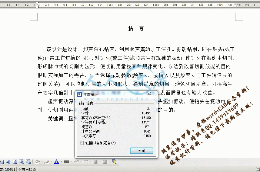
【带任务书+鉴定意见评阅表+外文翻译】【带任务书+开题报告+评阅评语表+答辩资格审查表+工作中期检查表+指导教师评阅表+实习日记+外文翻译+实习报告】【31页@正文10490字】【详情如下】【需要咨询购买全套设计请加QQ1459919609】.bat

A0-主轴箱.dwg

A0-机床总装配.dwg

A1-主轴.dwg

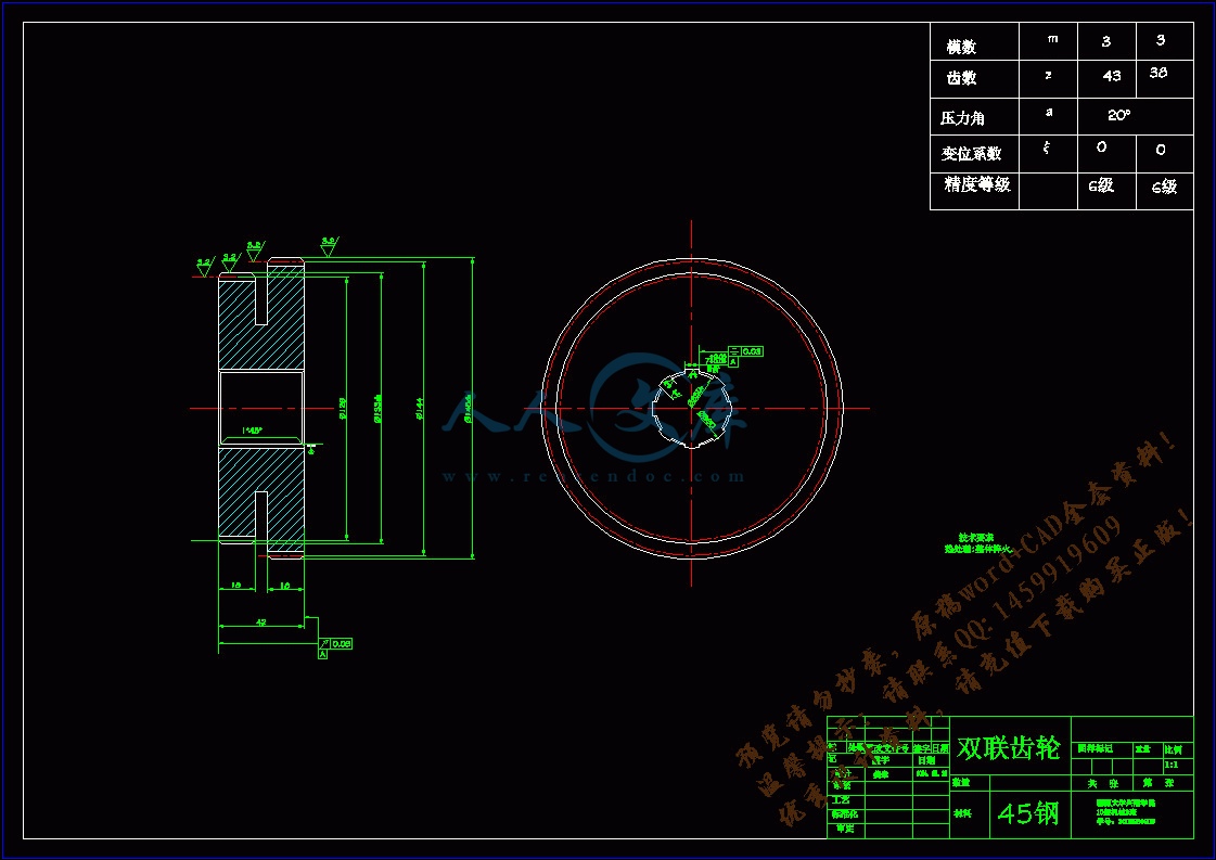
A2-双联齿轮.dwg

A2-双联齿轮2.dwg

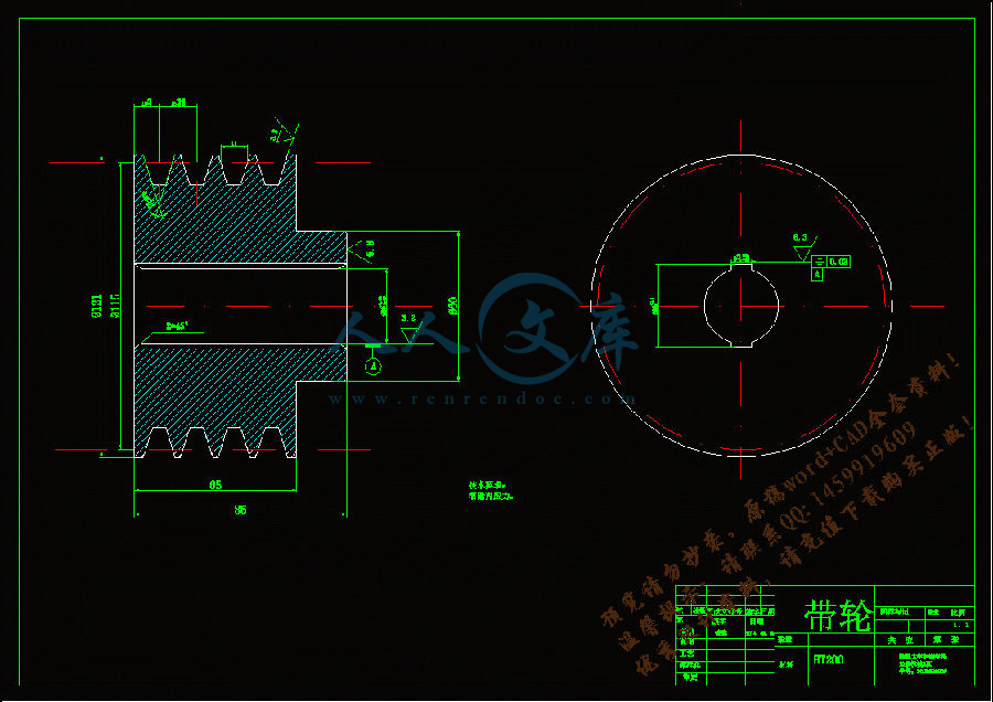
A2-带轮.dwg

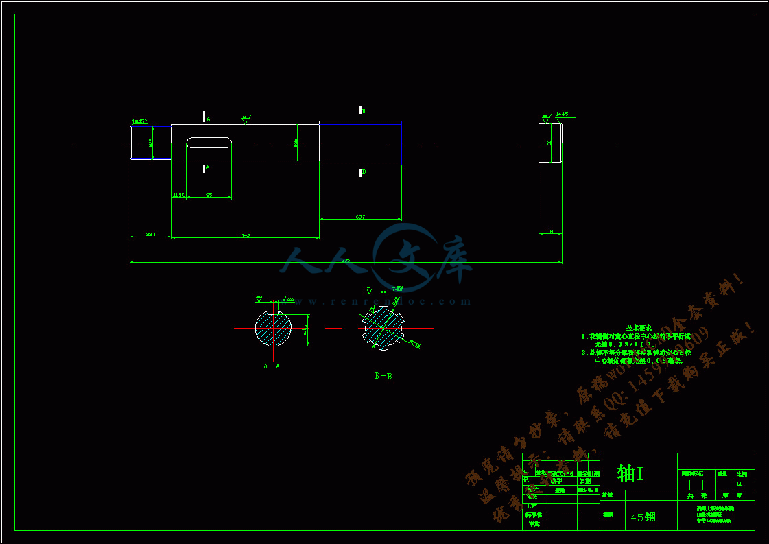
A2-轴I.dwg

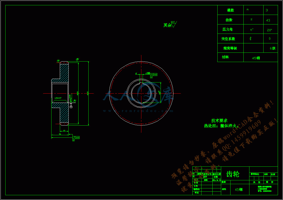
A2-齿轮.dwg

A2-齿轮2.dwg

任务书.doc

封面.doc

简介.txt

英文文献中文.doc

英文文献英文.pdf

评阅表.doc

说明书.doc

鉴定意见.doc

鉴定意见表.doc

湘潭大学兴湘学院

毕业论文(设计)任务书

论文(设计)题目         超声深孔钻床设计                                                                  

一、主要内容及基本要求

对国内外振动钻削工艺与方法进行分析,探讨;对超声震动原理与振动力学进行研究;对超声振动钻削装置进行设计;利用AutoCAD等软件对设计的机床按国标要求绘制2D装配图及主要零部件的2D零件图; 对钻床主轴箱进行设计。

基本要求如下

   1.绘制钻床装配图                  1张                                                                                  

   2.绘制钻床相关零件图              8套                                                                      

   3.编写设计说明书                  1份                                                              

   4.专业英语翻译                    1份                                                                  

二、重点研究的问题

(1)超声波振动钻床总体方案设计                                                                    

(2)钻床主轴箱的设计。                                              

(3)主执行机构设计(机构选型)及其结构设计。                              

三、进度安排

序号各阶段完成的内容起止时间

1收集资料第1-2周

2工艺分析,方案确定,绘制方案图第3周

3钻床结构设计,绘制总装图第4-8周

4绘制零件图第9-11周

5撰写设计说明书第12周

6外文翻译第13周

7毕业答辩第14周

四、 应收集的资料及主要参考文献

(1)曹凤国;《超声波加工技术》;化工工业出版社                                    

(2)胡敏强,金龙,顾菊平;《超声波电机原理与设计》                              

(3)赵淳生;《超声电机技术与应用》                                              

(4)超范国良, 陈传梁;《超声加工概况和未来展望》;1994年                        

(5)成大龙;《机械设计手册单行本机械振动/机架设计》;北京化学工业出版社 2004年  

(6)成大龙;《机械设计手册单行本机构设计》;北京化学工业出版社2004年            

(7)宁伟,许明翔,王耀俊;《固体间不同厚度界面层超声反射声学技术》;1995年      

(8)王亚非, 袁敬闳, 曾宏亮;《分层媒质中声波传输规律的研究压电与声光》;2000年  

(9)吴宗泽 罗圣国主编 《机械设计手册》高等教育出版社,2012年5月        

(10)张雄 焦峰 论文《超声加工技术的应用及其发展趋势》,2012年6月        

目录

摘  要1

前言2

第一章.超声和深孔加工技术的发展趋势4

1.1  超声振动加工技术发展趋势4

1.2  深孔加工发展状况5

第二章.机床主要参数的确定6

2.1  电机功率的确定6

2.2  主运动参数的确定6

2.3  标准公比值和标准转速数列7

第三章.确定结构式和绘制转速图9

3.1  求级数z9

3.2  确定结构式9

3.3  绘制转速图10

第四章.确定各级传动副齿轮的齿数12

4.1  确定齿轮的齿数12

4.2  验算传动比13

4.3  各轴及齿轮的计算转速的确定14

第五章.传动零件的初步计算16

5.1  传动轴直径初定16

5.2  主轴主要结构参数的确定16

5.3  齿轮模数计算和齿轮中心距的计算17

5.4  皮带的相关计算18

第六章.主要零件的验算21

6.1  齿轮的强度验算21

6.2  主轴的验算22

6.3  花键的验算26

致      谢28

参考文献29

英文文献30

摘  要

   该设计是设计一超声深孔钻床,利用超声震动加工深孔。振动钻削,即在钻头(或工件)正常工作进给的同时,对钻头(或工件)施加某种有规律的振动,使钻头在振动中切削,形成脉冲式的切削力波形,使切削用量按某种规律变化,以达到改善切削效能的目的。根据实际加工的需要,适当选择振动参数(频率v,振幅A以及频率v与工件转速n的比例关系),可以控制切屑的大小和形状,得到满意的切屑,避免切屑堵塞。可提高生产效率几倍到十几倍,提高加工精度1—2级,且加工表面质量也有较大改善。

   超声振动深孔加工钻床是利用超声振动系统对钻头施加振动,使钻头在振动中切削,使切削用两按规律变化,从而达到改善切削效能的目的。

关键词:超声振动,深孔加工,枪钻车床。

Abstract

This design is designs a supersonic deep hole drilling machine, the use supersonic vibration processes the deep hole. The vibration drills truncates, namely while the drill bit (or work piece) normal work to feed, (or work piece) exerts some kind of orderly vibration to the drill bit, causes the drill bit to cut in the vibration, forms the pulse -like cutting force profile, causes the cutting specifications according to some kind of rule change, achieves the improvement cutting potency the goal。According to the actual processing need, chooses the vibration parameter suitably (frequency v, oscillation amplitude A as well as frequency v with the work piece rotational speed n proportional relationship), may control the scrap the size and the shape, obtains satisfaction scrap, avoids the scrap jamming. May enhance production efficiency several times to several times, enhances the processing precision 1-2 level, also the processing surface quality also has improves greatly.

 The ultrasonic vibration deep hole processing drilling machine is the use ultrasonic vibration system to the drill bit infliction vibration, causes the drill bit to cut in the vibration, causes the cutting with two according to the rule change, thus achieves the improvement cutting potency the goal.

Key words: The ultrasonic vibration, the deep hole processing, butts the lathe.

前言

毕业设计是学生学完大学教学计划所规定的全部基础课和专业课后,综合运用所学的知识,与实践相结合的重要实践性教学环节。它是大学生活最后一个里程碑,是四年大学学习的一个总结,是我们结束学生时代,踏入社会,走上工作岗位的必由之路,是对我们工作能力的一次综合性检验。

1.毕业设计的目的

通过本次毕业设计,使达到以下几个效果:

(1)巩固、扩大、深化学生以前所学的基础和专业知识;

(2)培养学生综合分析、理论联系实际的能力;

(3)培养学生调查研究、正确熟练运用国家标准、规范、手册等工具书的能力;

(4)锻炼进行设计计算、数据处理、编写技术文件、绘图等独立工作能力。

总之,通过毕业设计使学生建立正确的设计思想,初步掌握解决本专业工程技术问题的方法和手段,从而使学生受到一次工程师的基本训练。

2、毕业设计的主要内容和要求

   本次毕业设计的主要内容是设计超声深孔钻床的主轴箱。具体设计内容和要求如下:

a)调查使用部门对机床的具体要求,现在使用的加工方法;收集并分析国内外同类型机床的先进技术、发展趋势以及有关的科技动向;调查制造长的设备、技术能力和生产经验等。

b)超声深孔钻床主轴箱的设计主要是设计主轴、传动轴及传动齿轮,确定各部分的相互关系;拟订总体设计方案,根据总体设计方案,选择通用部件,并绘制装配图和各零件的零件图;

c)进行运动计算和动力计算,绘制转速图;

d)其他零部件的设计和选择;

e)设计并选择皮带的型号和根数及带轮;

f)编制设计技术说明书一份。

3、程序和时间安排

毕业设计是实践性的教学环节,由于时间的限制,本次毕业设计不可能按工厂的设计程序来进行,具体的说,可以分以下几个阶段:

g)实习阶段,通过毕业实习实地调查、研究、收集有关资料,掌握深孔加工技术和超声加工技术,了解机床的结构、工作原理和设计的基本要求,花两周时间;

h)制定方案、总体设计阶段,花两周时间;

i)计算和技术设计阶段,绘制图纸,整理设计说明书,花四周时间;

j)答辩阶段,自述设计内容,回答问题,花半周时间。

第一章.超声和深孔加工技术的发展趋势

1.1  超声振动加工技术发展趋势

   超声加工是利用超声振动工具在有磨料的液体介质或干磨料中产生磨料的冲击、抛磨、液压冲击及由此产生的气蚀作用来去除材料,或给工具或工件沿一定方向施加超声频振动进行振动加工,或利用超声振动使工件相互结合的加工方法。超声加工技术在几十年里得到了迅速的发展,在超声振动切削、磨削加工、光整加工、塑性加工及其他方面的加工都有着广泛的研究与应用,尤其是在难加工材料领域解决了许多关键的工艺问题,取得了良好的效果。难加工材料促进了超声加工技术的发展,从而进一步促进了新材料的发展,可以预测,超声加工技术的应用会越来越广泛。

   1.1.1  超声加工技术发展概况

因超声加工技术在硬脆等难加工材料加工方面有较大的优势, 同时这些硬脆材料具有普通材料无法比拟的特点, 使其在工程上有着越来越广泛的应用, 国内外学者纷纷对超声加工技术的理论和工艺进行深入研究, 不断扬弃传统超声加工过程中所出现的缺点, 使超声加工这一技术的优点更为突出。

沈阳航空工业学院进行了精密深小孔的深入研究, 分别进 行了超 声镗孔、钻 孔和铰孔研究试验。张建中教授等人提出采用超声激振双刃镗削可较好弥补单刀镗削的缺陷与不足0, 提高系统的刚性, 进一步提高了精密深孔加工精度, 加工表面粗糙度为 Ra0. 1 Lm; 在铰孔试验中发现, 积屑瘤和磷次消失, 切削温度保持室温, 孔的圆度可达0. 004 mm, 圆柱度为0. 005 mm, 表面粗糙度为Ra0. 17 Lm; 超声钻孔的相关工艺实验表明, 这种钻削工艺减少了切削力, 降低了切削温度, 提高了零件的加工质量。

天津大学做了超声磨削加工工程陶瓷小孔的实验, 电镀金刚石的工具以超声频率和一定的振幅振动, 并加以高速旋转, 通过磨削液中的磨粒和工具对工件进行高速撞击、超声空化和砂轮磨粒的磨削, 达到材料去除的目的。结果表明, 超声磨削加工可明显提高陶瓷加工效率, 能明显减少普通磨削产生的表面裂纹和凹坑, 是陶瓷深孔精密高效加工的有效方法。

   1.1.2  超声加工技术发展趋势和未来展望

   超声加工技术已经涉及到许多领域,在各行各业发挥了突出的作用,但有关工艺与设备的相关技术有待于进一步研究开发。

   (1)超声振动切削技术

   随着传统加工技术和高新技术的发展,超声振动切削技术的应用日益广泛,振动切削研究日趋深入,主要表现在以下几个方面。

1研制和采用新的刀具材料。在现代产品中,难加工材料所占的比例越来越大,对机械零件加工质量的要求越来越高。

2对振动切削机理深入研究。

3超声椭圆振动切削的研究与推广。    

a超声铣削加丁技术。基于分层去除技术思想的超声铣削加工技术正在被更多的学者所关注。

   b超声复合加工技术

   目前,超声电火花机械三元复合加工技术已经得到较快的发展。哈尔滨工业大学利用超声电火花磨料三元复合加工技术对不锈铜进行加工,解决了电火花小孔加工中生产率和表面质量不能兼顾的矛盾,具合较好的应用前景。

   c微细超声加工技术

随着以微机械为代表的工业制品的日益小型化及微细化,特别是随着晶体硅、光学玻璃、工程陶瓷等硬脆材料在微机械中的广泛应用,硬脆材料的高精度三维微细加工技术己成为世界各国制造业的一个重要价究课题。

同其他特种加工技术一样,起声加工技术在不断完善之中.正向着高精度、微细化发展,微细超声加丁技术合理成为微电子机械系统(MEM5)技术的有力补充。

参考文献:

[1] 冯辛安主编《机械制造装备设计》机械工业出版社出版,2003年6月

[2]濮良贵 纪名刚主编《机械设计》高等教育出版社出版,2001年4月

[3]王世清主编《深孔加工技术》西北工业大学出版社出版,2003年10月

[4]李洪主编《实用机床设计手册》辽宁科学技术出版社出版,1999年1月

[5]黄鹤汀主编《金属切削机床》下册 机械工业出版社出版,1998年5月

[6]赵世华主编《金属切削机床》航空工业出版社出版,1996

[7]曹凤国主编《超声加工技术》化学工业出版社出版,2004年8月

[8]孙桓 陈作模主编《机械原理》(第六版高等教育出版社出版,2002年8月

[9]吴宗泽 罗圣国主编 《机械设计手册》高等教育出版社,2012年5月

[10]张雄 焦峰 论文《超声加工技术的应用及其发展趋势》,2012年6月

内容简介:
湘潭大学兴湘学院毕业论文(设计)任务书论文(设计)题目 超声深孔钻床设计 学 号 2008960909 学生姓 姜维 专 业 机械设计制造及其自动化 指导教师姓名: 李玉平 系主任: 刘柏希 一、主要内容及基本要求对国内外振动钻削工艺与方法进行分析,探讨;对超声震动原理与振动力学进行研究;对超声振动钻削装置进行设计;利用AutoCAD等软件对设计的机床按国标要求绘制2D装配图及主要零部件的2D零件图; 对钻床主轴箱进行设计。基本要求如下 1绘制钻床装配图 1张 2绘制钻床相关零件图 8套 3编写设计说明书 1份 4专业英语翻译 1份 二、 重点研究的问题(1)超声波振动钻床总体方案设计 (2)钻床主轴箱的设计。 (3)主执行机构设计(机构选型)及其结构设计。 三、 进度安排序号各阶段完成的内容起止时间1收集资料第1-2周2工艺分析,方案确定,绘制方案图第3周3钻床结构设计,绘制总装图第4-8周4绘制零件图第9-11周5撰写设计说明书第12周6外文翻译第13周7毕业答辩第14周四、 应收集的资料及主要参考文献(1)曹凤国;超声波加工技术;化工工业出版社 (2)胡敏强,金龙,顾菊平;超声波电机原理与设计 (3)赵淳生;超声电机技术与应用 (4)超范国良, 陈传梁;超声加工概况和未来展望;1994年 (5)成大龙;机械设计手册单行本机械振动/机架设计;北京化学工业出版社 2004年 (6)成大龙;机械设计手册单行本机构设计;北京化学工业出版社2004年 (7)宁伟,许明翔,王耀俊;固体间不同厚度界面层超声反射声学技术;1995年 (8)王亚非, 袁敬闳, 曾宏亮;分层媒质中声波传输规律的研究压电与声光;2000年 (9)吴宗泽 罗圣国主编 机械设计手册高等教育出版社,2012年5月 (10)张雄 焦峰 论文超声加工技术的应用及其发展趋势,2012年6月 湘潭大学兴湘学院毕业设计题 目: 超声深孔钻床设计 专 业: 机械设计制造及其自动化 学 号: 2008960909 姓 名: 姜维 指导教师: 李玉平 完成日期: 2014年5月28日 湘潭大学兴湘学院毕业设计说明书题 目: 超声深孔钻床设计 专 业:机械设计制造及其自动化 学 号: 2008960909 姓 名: 姜维 指导教师: 李玉平 完成日期: 2014年5月28日 Micro-feed Mechanism with High-Resolution and Large-Stroke Based on Friction Drive Haitao Liu, Zesheng Lu School of Mechantronics Engineering, Harbin Institute of Technology ABSTRACT Based on friction driving principle, design a long stroke length and high resolution walking micro-feeding device driven by piezoelectric ceramic elements and combined with the screw shaft and aerostatic guide way. The design was made to the adjustable preload device by flexible four-bar linkage. The static properties of flexible linkage device are analyzed with FEM. The transmission characteristics of micro-feeding device are exhaustively analyzed. Keywords: Friction drive, Piezoelectric actuator, Flexure hinge,Finite element 1. INTRODUCTION Aspheric optics has been widely used in industries such as aviation, aerospace, national defense and so on. However, the manufacture of large aspheric optics faces many problems such as great difficulty, low efficiency, high cost, increased requirement on process equipment etc 1, 2. In order to arrive at high precision, the micro displacement resolution of ultra-precision machine must be further advanced, so as to compensating the processing error online. Therefore, the design of micro-feed mechanism has become one of the key technologies 3-7. PZT is the new micro-feed mechanism developed in recent years. It has the advantages such as small volume, large power, high resolution, and high frequency response and so on and phenomena such as no heating, no backlash and mucosity, so its widely used micro controller in micro-feed mechanism. Nowadays, friction gearing mechanism is gradually been acquired and used 8, 9. 2. STRUCTURE AND OPERATING PRINCIPLE OF MICRO-FEED MECHANISM The micro-feed mechanism is made up of three parts: friction gearing, ball screw and static-pressure air-bearing guide way. Micro-feed mechanism uses the piezoelectricity ceramic friction gearing block, which twist up the sleeve and drive the ball screw, so as to bring along the air-bearing guide way to realize the micro-feed movement. The structure is shown as Figure 1. Figure 1: (a) Structure of the feed mechanism As shown in Figure 2, the operating principle of the feed mechanism is that, friction gearing sleeve connects with ball screw, four friction gearing blocks are placed symmetrically at both sides of the sleeve. Each block is droved by the corresponding piezoelectricity ceramic used for feeding and is gripped by the corresponding gripping mechanism, which is droved by the piezoelectricity ceramic used for gripping to produce clamp force. When feeding mechanism works, the E-mail:, Phone: (0451)15904608295, Address: Mailbox 413, Harbin Institute of Technology, Post Code: 150001. 2 1 3 4 5 6 7 1-Bearing bracket 2-Friction gearing block 3 Friction gearing sleeve 4-Static-pressure air-bearing guide way 5- Ball screw 6- Piezoelectricity ceramic base 7-Piezoelectricity ceramic used for feeding 3rd International Symp. on Advanced Optical Manufac. and Testing Tech.: Advanced Optical Manufacturing Technologies, edited by Li Yang, Yaolong Chen, Ernst-Bernhard Kley, Rongbin Li, Proc. of SPIE Vol. 6722, 67222E, (2007) 0277-786X/07/$18 doi: 10.1117/12.783140Proc. of SPIE Vol. 6722 67222E-1 piezoelectricity ceramic used for gripping on the same side drive both the friction gearing blocks to work in certain orderliness, so as that the friction gearing sleeve turn continuously. Figure 1: (b) Picture of the feed mechanism Figure 2: Operating principle of the feeding mechanism 3. DESIGN OF THE ADJUSTABLE PRETIGHTENING MECHANISM An adjustable retightening mechanism is required in the friction gearing mechanism, which must has enough pretightening force. The typical pretightening methods are plate spring pretightening mechanism, helical pretightening mechanism, and air pressure pretightening mechanism and so on. The retightening mechanism designed in this paper is flexible parallel four bars mechanism. Its droved by piezoelectricity ceramic to supply pretightening force. The pretightening force can be changed by controlling the input voltage of piezoelectricity ceramic. As shown in Figure 3, use the finite element software to analysis the static characteristic. When the drive force of piezoelectricity ceramic is 500N in maximum, the rigidity of flexible four bars mechanism, analyzed by finite element software, is K=24.15N/m, and the maximum stress of flexible hinges is =32.7Mpa. If there is no distortion in flexible four bars mechanism (that is when the friction gearing blocks contact rigidly), the output force of piezoelectricity ceramic will completely translates to pretightening force through the flexible four bars mechanism. 4. DRIVE CHARACTERISTIC ANALYSIS OF THE MECHANISM Studying and mastering the drive characteristic of mechanism redounds to adopting the proper measures to improve the whole performance and provides the design basis for designing the control system. 4.1 Drive torque Friction gearing block Friction gearing block Gripping mechanism Gripping mechanism Proc. of SPIE Vol. 6722 67222E-2AN When system starts, there is a problem on initial inertia moment as a result of the existence of parts quality. To research the drive torque, choose the friction gearing sleeve as subject investigated. According to the theory that the kinetic energy of gearing train is same before and after conversion, the rotary inertia of each part is transformed to friction sleeve. Because of that, we can get the rotary inertia after conversion is Figure 3: The static characteristic assay plan of pretightening mechanism 2222TSLD1()()()2222pppJm rmmm=+ (1) Where p is pitch of lead screw, m; r is radius of the friction sleeve, m; mS is quality of the ball screw, kg; mT is quality of the friction sleeve, kg. Through the above analysis, we get the equivalent rotary inertia of friction sleeve. Now we choose the friction sleeve as subject investigated to discuss the drive torque(drive force)that is needed when device starts and its influencing factors. The following equation works when device starts: J MF r= (2) Where J is equivalent rotary inertia, kgm2; is angular acceleration of friction sleeve, rad/s2; r is radius of the friction sleeve, m; M is drive torque, Nm; (b) Node motion nephogram (c) Von-mise stress envelope (a) Structure of the pretightening mechanism Proc. of SPIE Vol. 6722 67222E-3 F is drive force(breakout friction between friction block and friction sleeve), N. When system starts, a condign drive deflecting couple should be applied on the friction sleeve, in order that the sleeve can have certain angular acceleration. The drive deflecting couple is generated by the output force of piezoelectricity ceramic. From equation 2 we can get that the equivalent rotary inertia of system, radius of the friction sleeve and drive force of the piezoelectricity ceramic (breakout friction between friction block and friction sleeve) are the influencing factor of mechanism start, so we should think over the influence of each factor to ensure the normal start of mechanism. Same questions exist when feed mechanism stop moving. 4.2 Driving rigidity The driving rigidity is one of the important driving characteristics of feed mechanism. Now we will analyze the driving rigidity of feed mechanism in detail as following. The rigidity of the feed mechanism is the cascade connection of the each segment rigidity of the feed mechanism, which has the calculated equation as follows: YFSSNBHD111111111KKKKKKKKK=+ (3) Where K is the total rigidity of the feed mechanism; KY is the rigidity of piezoelectricity ceramic; KF is the touching rigidity of surface in contact between friction block and friction sleeve; KS is the axial rigidity of lead screw; KS is the axial rigidity changed from the torsional rigidity of lead screw; KN is the rigidity of nut; KB is the rigidity of axial bearing; KH is rigidity of nut bracket and bearing block; KD is the axial rigidity of nut link block; Here is the analysis and calculation of part rigidity. 4.2.1 Rigidity of the piezoelectricity ceramic The piezoelectricity ceramic in this paper is the ceramic micro positioner typed WTYD0808055 produced by China Electronics Technology Group Corporation No.26 Research Institute. Its rigidity measured through experiment is 15.15N/m, as shown in Figure 4. 4.2.2 Touching rigidity of surface in contact between friction block and friction sleeve Two objects contacting with each other will have certain tangential transition before relative slip in the action of tangential external force, which is called pre-displacement. The proportional relation between force and displacement reflects a rigidity characteristic in fact 10. The corresponding rigidity now is: 1 31 3FKkrN= (4) Where k is const; N is normal pressure; r is the radius of idealized sphere on friction surface. Its clear in the equation that, in special friction gearing system, k is got from experiment, r is const, the only influencing factor of touching rigidity is normal pressure N. Its evident that the larger N is, the larger the touching rigidity K is. Proc. of SPIE Vol. 6722 67222E-4 Figure 4: Rigidity curve of piezoelectricity ceramic 4.2.3 Axial rigidity changed from the torsional rigidity of lead screw The dimension of driving chain needs to be transformed uniformly when calculating its rigidity. Therefore, the torsional rigidity must be transformed into axial rigidity as the following equation: PTGJMKL= (5) ST4tan()KKpd=+ (6) Where is the rising angle of lead screw, (); d is the diameter of lead screw, mm; F is the axial force of lead screw, N; M is the input moment of lead screw, Nmm; is the friction angle between lead screw and nut, (); KT is the torsional rigidity of lead screw, Nmm/rad; is the torsional deformation of lead screw, rad; p is the lead of lead screw, mm; G is the shear modulus of elasticity of lead screw material, Mpa; JP is the inertia moment of cross section, mm4, JP=d4/32; L is the maximum distance from loading point to two thrust bearing, mm. The axial rigidity of nut link block can be gained by the finite element analysis. The rigidity of nut bracket and bearing block is very large, which can be dismissed. The rigidity of other parts can be got by looking up table and calculating. In a word, by deducing the equation of drive rigidity of feed mechanism, we have found the influencing factors of driving rigidity caused by each driving segment, which offers the basis for further study on the driving characteristic. 5. EXPERIMENTAL STUDY OF THE FEED MECHANISM 5.1 Foundation of the experiment system 01234567809.819. 629. 439. 24958. 868. 678. 4N SProc. of SPIE Vol. 6722 67222E-5- -l:0:-V_ As shown in Figure 5, the experiment system is made up of feed mechanism, computer, piezoelectricity ceramic driver and its power supply and the inductance amesdial. Figure 5: Foundation of experiment system This paper uses a control method based on average curve model to set up the open loop control model. Above all, measure the experimental curve of relation between piezoelectricity ceramic control voltage and slide carriage distance. Using the Matlab software to fit the line with cubic algebraic multinomial, and the fitted line and fitted error line are as shown in Figure 6, from which we get the corresponding relational expression of control voltage and distance and therefore control the distance of feed mechanism. Figure 6: Fit with cubic algebraic multinomial Relational expression of control voltage and distance is as shown in equation 7: 73521.8 105.3 100.00440.022xuuu= + (7) Where x is the output distance, m; u is the control voltage, V. 5.2 Experimental study of system resolution As shown in Figure 7, piezoelectricity ceramic has certain elongation. At this time, the distance of micro working table is 0.15m. Then step elongating gradually on this base and keep 1.5s in each moment. The sampling time is 100ms. The resolution curve can be gained by measuring the practice distance of micro feed mechanism using the inductance amesdial. a) Fitted line b) Fitted error line Proc. of SPIE Vol. 6722 67222E-60.5IIIa45 Figure 7: Distance resolution curve of feed mechanism 6. CONCLUSION A step micro feed mechanism with long march and high resolution was designed in this paper, and the following conclusions were concluded: 1. Designed the pretightening mechanism based on the piezoelectricity ceramic flexible iron hinges and analyzed its static characteristic using the finite element software; 2. Analyzed the starting torque of micro feed mechanism and calculated the equivalent rotary inertia; analyzed the driving rigidity characteristic of micro feed mechanism and found its influencing factors; 3. The march of the micro feed mechanism can reach 300mm, and the resolution is less than 0.05m. REFERENCES 1. Seugng-Bok Choi, Sang-Soo Han. Position Control System Using ER Clutch and Piezoactuator. Pr
温馨提示:
1: 本站所有资源如无特殊说明,都需要本地电脑安装OFFICE2007和PDF阅读器。图纸软件为CAD,CAXA,PROE,UG,SolidWorks等.压缩文件请下载最新的WinRAR软件解压。
2: 本站的文档不包含任何第三方提供的附件图纸等,如果需要附件,请联系上传者。文件的所有权益归上传用户所有。
3.本站RAR压缩包中若带图纸,网页内容里面会有图纸预览,若没有图纸预览就没有图纸。
4. 未经权益所有人同意不得将文件中的内容挪作商业或盈利用途。
5. 人人文库网仅提供信息存储空间,仅对用户上传内容的表现方式做保护处理,对用户上传分享的文档内容本身不做任何修改或编辑,并不能对任何下载内容负责。
6. 下载文件中如有侵权或不适当内容,请与我们联系,我们立即纠正。
7. 本站不保证下载资源的准确性、安全性和完整性, 同时也不承担用户因使用这些下载资源对自己和他人造成任何形式的伤害或损失。
提示  人人文库网所有资源均是用户自行上传分享,仅供网友学习交流,未经上传用户书面授权,请勿作他用。
关于本文
本文标题:超声深孔钻床的设计【优秀】【word+9张CAD图纸全套】【毕设】
链接地址:https://www.renrendoc.com/p-303266.html

官方联系方式

2:不支持迅雷下载,请使用浏览器下载   
3:不支持QQ浏览器下载,请用其他浏览器   
4:下载后的文档和图纸-无水印   
5:文档经过压缩,下载后原文更清晰   
关于我们 - 网站声明 - 网站地图 - 资源地图 - 友情链接 - 网站客服 - 联系我们

网站客服QQ:2881952447     

copyright@ 2020-2025  renrendoc.com 人人文库版权所有   联系电话:400-852-1180

备案号:蜀ICP备2022000484号-2       经营许可证: 川B2-20220663       公网安备川公网安备: 51019002004831号

本站为文档C2C交易模式,即用户上传的文档直接被用户下载,本站只是中间服务平台,本站所有文档下载所得的收益归上传人(含作者)所有。人人文库网仅提供信息存储空间,仅对用户上传内容的表现方式做保护处理,对上载内容本身不做任何修改或编辑。若文档所含内容侵犯了您的版权或隐私,请立即通知人人文库网,我们立即给予删除!