相关资料.doc

围板包装箱自动生产线合围装置设计【优秀】【带UG三维】【word+11张CAD图纸】【毕设】

收藏

资源目录
跳过导航链接。
压缩包内文档预览:(预览前20页/共22页)
预览图 预览图 预览图 预览图 预览图 预览图 预览图 预览图 预览图 预览图 预览图 预览图 预览图 预览图 预览图 预览图 预览图 预览图 预览图 预览图
编号:312881    类型:共享资源    大小:7.22MB    格式:RAR    上传时间:2014-08-17 上传人:QQ14****9609 IP属地:陕西
50
积分
关 键 词:
围板 包装箱 自动生产线 合围装置
资源描述:

围板包装箱自动生产线合围装置设计【优秀】【word+11张CAD图纸】【毕业设计】

【带任务书+开题报告++外文翻译】【40页@正文21900字】【详情如下】【需要咨询购买全套设计请加QQ1459919609】.bat

pdf打印图

UGtufujian

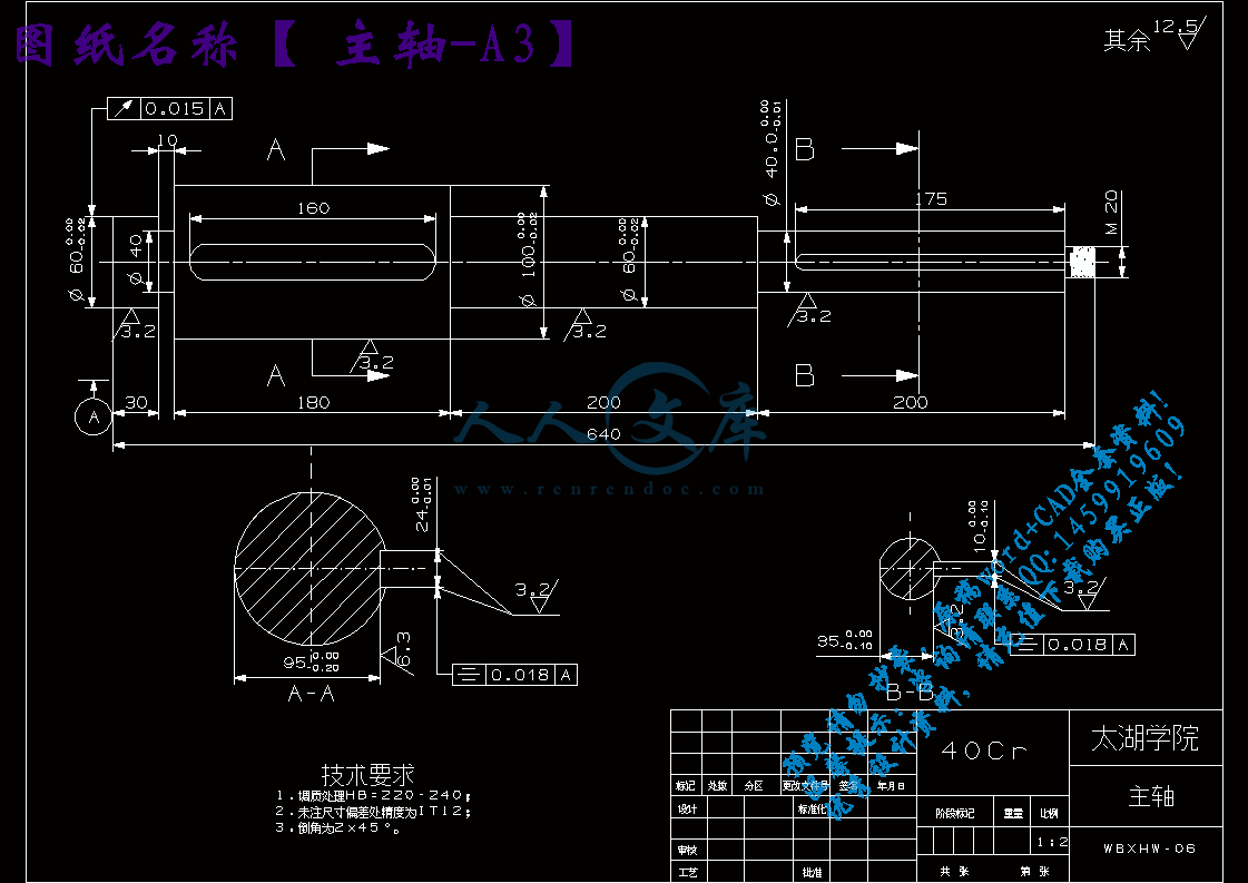
主轴-A3.dxf

任务书.doc

合围装置总装图-A0.dxf

围板包装箱自动生产线合围装置设计正文.doc

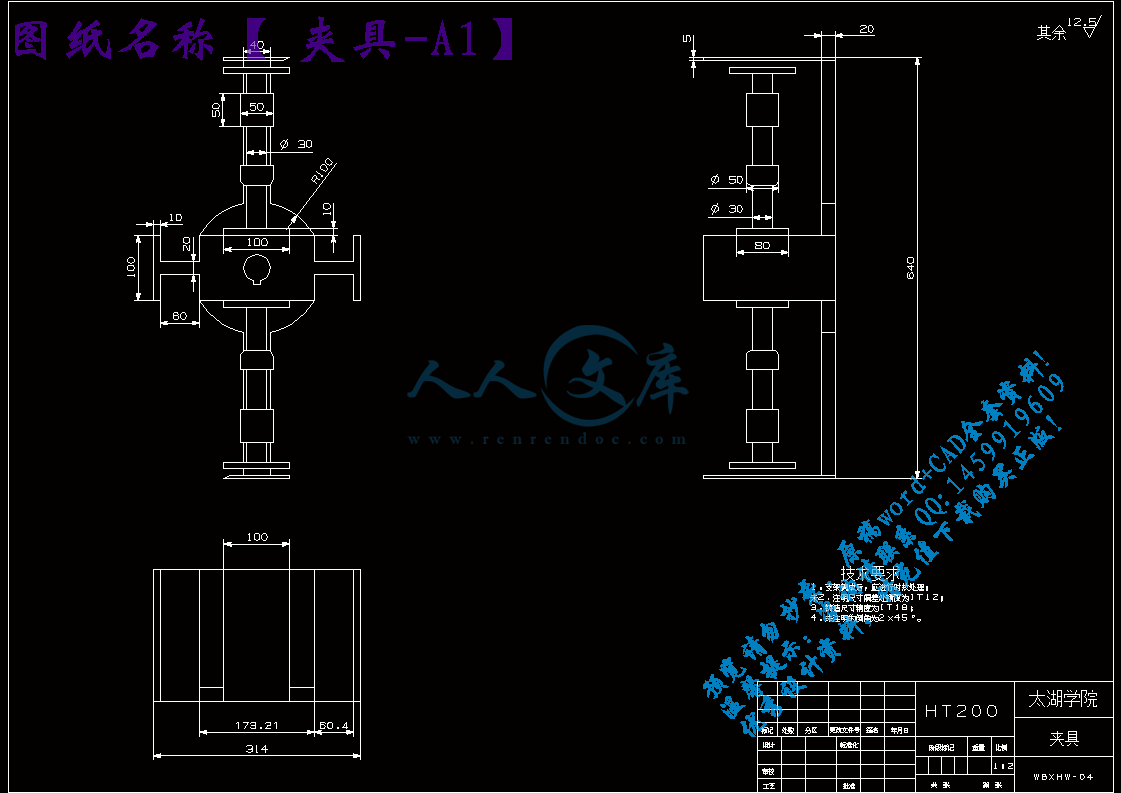
夹具-A1.dxf

夹具机架-A2.dxf

工作台-A1.dxf

开题报告.doc

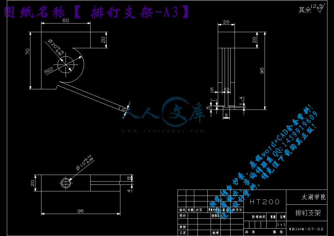
排钉支架-A3.dxf

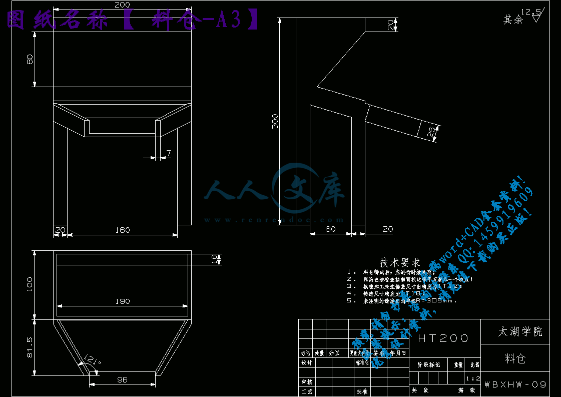
料仓-A3.dxf

机架-A1.dxf

相关资料.doc

翻译.doc

计划周记进度检查表3.xls

转盘-A4.dxf

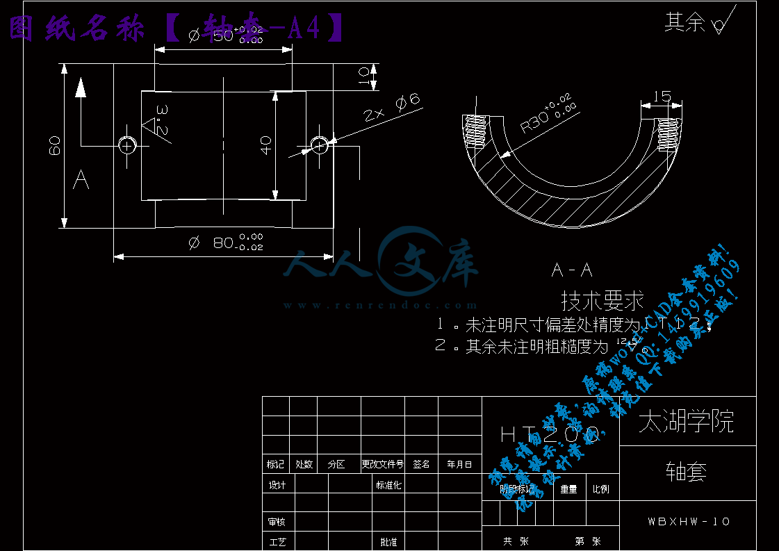
轴套-A4.dxf

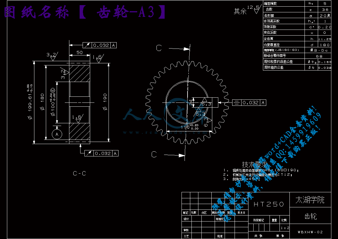
齿轮-A3.dxf

无锡太湖学院

 信 机 系   机械工程及自动化  专业

毕 业 设 计论 文 任 务 书

一、题目及专题:

1、题目  围板包装箱自动生产线合围装置设计              

2、专题                                                

二、课题来源及选题依据

1、课题来源:来源于工厂

2、选题依据:围板箱是由托盘、箱体和箱盖三部分组成,组成每层围板的四片木板用铰链连接。由于装箱的灵活性、对装载物的适应性和重复使用性,围板箱被广泛应用与机械、化工、电子、五金一集其他领域的物流配送,具有能回收、降低成本、环保等优点。

作为产品外包的物流设施,围板箱越来越受客户的欢迎,使用量巨大。然而, 现有的围板箱生产方式落后, 在生产中人为因素较大,这使得围板箱的生产上存在着生产效率低,质量不稳定等缺陷。 这严重影响着围板箱的应用。为了提高劳动生产率, 降低工人劳动强度, 节约生产成本, 我们对围板箱的现有生产工艺进行了研究,设计出了适应与围板箱生产的自动合围装置。

三、本设计(论文或其他)应达到的要求:

①熟练运用UG绘制三维模型图      

②熟悉围板包装箱生产加工的过程    

③了解近几年对围板箱生产工艺的改进

④设计出合理的围板箱合围装置    

摘  要

   围板箱作为产品外包的物流设施,围板箱越来越受客户的欢迎,使用量巨大。然而,现有的围板箱生产方式落后,在生产中人为因素较大,这使得围板箱的生产上存在着生产效率低,质量不稳定等缺陷。这严重影响着围板箱的应用。为了提高劳动生产率,降低工人劳动强度,节约生产成本,我们对围板箱的现有生产工艺进行了研究,通过对原有围板箱生产工艺的分析,设计了适应于围板箱的自动合围装置。

   围板包装箱在生产过程中主要分为上料、拼接、钻铆、合围等几部分工序,本论文主要是设计合围装置的说明。将2个用铰链连起来的2片木板的两端分别铆接起来。连接起来的木板链一端是只有孔,另一端是仅铆接了半面铰链(另半面没有铆接)。首先第一步是铆接了半面铰链的一端在前另一端在后,通过挡板来约束定位;第二步运用气压缸来推动夹紧块来夹紧木板,使之不能像对滑动;之后在是夹紧装置绕主轴旋转180°,在重复第一、二步操作(第二次只旋转90°),使两块木板合围,之后通过平移夹紧旋转装置使需要铆接的部分移到铆接机上,在上铆钉铆接从而完成合围。

关键词:围板箱;合围;铆接;自动生产线

Abstract

Hoardings box as outsourcing logistics facilities around the crate more and more popular with customers , a huge amount of use . However, the backward the existing hoardings box mode of production in the production of man-made factors , which makes the production of hoardings box there is low productivity, unstable quality defects . This has seriously affected the application of hoardings box . In order to improve labor productivity, reduce labor intensity , reduce production costs , we conducted a research on the hoardings Box existing production process through the analysis of the production process of the original hoardings box , designed to adapt to the hoardings box automatically encirclement devices.

The hoardings box on materials , stitching, drilling and riveting , encircled in the production process is divided into several parts process of this thesis is the design of the encirclement device . Two hinges to link two of the ends of the planks were riveted . Connected one end of the wood chain is the only hole , the other end is only half a face riveted hinge ( the other half of a riveting ) . First step is riveting half-face one end of the hinge in front the other end of the baffle to constrain the positioning ; second step the use of pneumatic cylinder to push the clamping block for clamping wood , so they can not like sliding ; after clamping device around the spindle 180 ° , repeat the first and second steps ( second rotation only 90 ° ) , so that the two pieces of wood encircled by the pan after clamping rotary device to make part moved to the riveting machine riveting , thus completing the encirclement on the rivet .

Key words: Hoardings box ; encirclement ; riveting ; automated production lines

目  录

摘  要III

AbstractIV

目  录V

1 绪论1

1.1本课题的研究内容和意义1

1.2国内外的发展概况1

1.3 本文主要设计内容4

2 生产线总体结构设计5

2.1 围板箱生产工艺分析5

2.1.1 围板尺寸参数5

2.1.2 生产线工艺流程5

2.1.3 总体结构7

2.1.4 生产节拍的拟定7

2.1.5 控制系统8

3 各部分具体设计9

3.1木料传入部分设计9

3.2 木料的定位夹紧装置设计9

3.3 旋转移位装置10

3.3.1 电动机的选取11

3.3.2 传动比的分配13

3.4 伸缩移位19

3.5 铆接20

3.5.1 定位20

3.5.2 送钉装置20

3.5.3 铆接装置29

4 结论与展望35

致  谢36

参考文献37

1 绪论

1.1 本课题的研究内容和意义

围板箱是由托盘、箱体和箱盖三部分组成,组成每层围板的四片或六片木板用L型铰链连接。由于装箱的灵活性、对装载物的适应性和重复使用性,围板箱被广泛应用于机械、化工、电子、五金以及其他领域的物流配送,具有能回收、降低成本、环保等优点。

围板箱的优点:

1. 围板箱的长、宽根据托盘的尺寸确定,使用层数可根据承载物的高度来决定,最大限度地提高箱体空间的利用率。

2. 由于无钉化作业,显著地降低了工人在装卸过程中发生工伤的风险。

3. 不存在因箱体的部分损坏而令整箱报废的情况,对于同一尺寸,可实现完全互换使用。

4. 运输时可将围板折叠为双层或四层相连接的木板结构摆放在托盘上,大大地减少贮运体积,有效的降低运输成本。

在循环包装系统里,方便灵活的围板箱有着无可比拟的优势。这是一种标准的物流器具,损坏的顶盖与侧板很容易进行替换,整体循环包装系统的投资比较低廉,而使用寿命则可达十年之久,这也是一种可靠的坚固的可以折叠的包装系统。由于装箱的灵活性、对装载物的适应性和重复使用性,围板箱被广泛运用于机械、化工、电子、五金以及其他领域,此外还具有传统木箱不具备的很多优点,因而这种产品在国外也特别受欢迎,运用也很普遍。

参考文献

[1]  刘平, 李原,张开富, 余剑锋. 压铆过程阶段划分与压铆力计算[J]. 机械科学与技术, 2009(4), Vol.28 No.4: 514-521.

[2]  刘朝儒, 彭福荫, 高政一. 机械制图[M], 北京: 高等教育出版社. 2001.

[3]  王文斌. 机械设计手册[M]. 北京: 机械工业出版社, 2004.

[4]  周延, 李中行. 电主轴的电动机及其驱动模块[J]. 制造技术与机床, 2003(9): 86-87.

[5]  成大先. 机械设计手册单行本——机构[M], 北京: 化学工业出版社出版, 2004.

[6]  齿轮手册编委会. 齿轮手册[M]. 北京: 机械工业出版社, 1990..

[7]  王振华. 实用轴承手册[M]. 上海: 上海科学技术文献出版社, 1991.

[8]  吴宗泽. 机械结构设计[M]. 北京: 机械工业出版社, 1988.

[9]  吴宗泽. 机械零件习题集[M]. 北京: 高等教育出版社, 1983.

[10] 费军. 自动钻铆技术发展现状与应用分析[J]. 航空制造技术, 2005, 第6章: 42-44.

[11] 张佩勤, 王连荣编. 自动装配与柔性装配技术[M]. 北京: 机械工业出社, 1998, 5.

[12] 黄志昌编. 自动化生产设备原理及应用[M]. 北京: 电子工业出版社, 2007, 12.

[13] 尚久浩主编. 自动机械设计[M]. 北京: 中国轻工业出版社, 2008, 5.

[14]  Langrand B. Riveted Joints Embrittlement, Validation of Riveting Process FE Model[R]. ONERA-Lille Report 98/01, 1998.

[15]  Urban M R. Analysis of the fatigue life of riveted sheet metal helicopter airframe joints[J]. International Journal of Fatigue, 2003(25): 1013—1026.

[16]  Kelly B, Costello C. FEA modeling of setting and mechanical testing of a luminum blind rivets[J]. Materials Processing Technology, 2004, 153-154: 74-79.

[17]  Blanchot V, Daidie A, Riveted assembly modeling study and numerical characterisation of a riveting process[J]. Journal of Materials Processing Technoloty, 2006, 18(1-3): 201-209.

[18]  Poirot Rache, Prat Laurent, Gourdon Christophe, Diard Catherine, Jean-Marie Autret. Fast Bath to Continuous Solid -Liquid Extraction from Plants in Continuous Industrial Extraction[J]. Chem. Eng. Technol, 2007, 30(1):  46-51

[19] 张世亮. 液压与气动传动[M]. 北京: 机械工业出版社, 2006.

[20] 王晓方. 液压与气动技术[M]. 北京: 中国轻工业出版社, 2006.

[21] 冯辛安主编. 机械制造装备设计[M]. 北京: 机械工业出版社, 2005, 12.

[22] 黄志昌编. 自动化生产设备原理及应用[M]. 北京: 电子工业出版社, 2007, 12.

[23] 成大先. 机械设计图册(第一卷)[M]. 北京: 化学工业出版社, 2000.

[24] 周延, 李中行. 主轴的电动机及其驱动模块[J]. 制造技术与机床,2003(9): 86-87.

[25] 李涵. 基于双机器人协同的自动钻铆终端器及其自动供钉装置的设计与研究[D]. 浙江: 浙江大学, 2010, 32-47.

[26] 周宗党, 龚建云. 自动钻铆机铆钉排列系统设计[J]. 中国西部科技, 2008(1): 8-11.

[27] 尚久浩. 自动机械设计[M]. 北京: 中国轻工业出版社. 2003.

[28] 孙 桓, 陈作模. 机械原理(第六版)[M]. 北京: 高等教育出版社, 2004.

[29] 曲立娜. 大尺寸薄壁工件自动钻铆机结构的研究与设计[D]. 大连: 大连理工大学, 2009.

[30] 张仁杰. 液压缸的设计制造和维修[M]. 机械工业出版社, 1989.

[31] 尚久浩. 自动机械设计[M]. 北京: 中国轻工业出版社, 2008, 5.

内容简介:
编号无锡太湖学院毕业设计(论文)相关资料题目:围板包装箱自动生产线合围装置设计 信机 系 机械工程及自动化专业学 号: 0923113学生姓名: 顾一涛 指导教师: 何雪明 (职称:副教授) 2013年5月25日目 录一、毕业设计(论文)开题报告二、毕业设计(论文)外文资料翻译及原文三、学生“毕业论文(论文)计划、进度、检查及落实表”四、实习鉴定表无锡太湖学院毕业设计(论文)开题报告题目:围板包装箱自动生产线合围装置设计 信机 系 机械工程及自动化 专业学 号: 0923113 学生姓名: 顾一涛 指导教师: 何雪明 (职称:副教授 ) 2013年2月25日 课题来源工厂科学依据(1)课题科学意义围板箱是由托盘、箱体和箱盖三部分组成,组成每层围板的四片木板用铰链连接。由于装箱的灵活性、对装载物的适应性和重复使用性,围板箱被广泛应用与机械、化工、电子、五金一集其他领域的物流配送,具有能回收、降低成本、环保等优点。作为产品外包的物流设施,围板箱越来越受客户的欢迎,使用量巨大。然而, 现有的围板箱生产方式落后,在生产中人为因素较大,这使得围板箱的生产上存在着生产效率低,质量不稳定等缺陷。这严重影响着围板箱的应用。为了提高劳动生产率,降低工人劳动强度,节约生产成本,我们对围板箱的现有生产工艺进行了研究,设计出了适应与围板箱生产的自动合围装置。(2)围板包装箱生产的现状及其发展前景 在现在的生产中采用的是人工钻铆的生产方式,生产效率很低。合围是将用铰链连接起来的木板 4 片木板两端铆接起来。连接起来的木板链一端是插好了铆钉,另一端是仅铆接了半面铰链(另半面没有铆接),将两端对齐,使插好铆钉的一端的铆钉头,穿过没有铆接的半面铰链上的孔,然后,人工在铆接机上分别进行铆接(每次仅插入1个铆钉,铆接 4 次),完成合围。设计内容本论文主要设计的内容是如何将四块木板用铆接的方式合围起来,首先是要将每两块木板用铰链连接起来,然后通过夹具夹紧旋转,将一组两个木板链形成合围的态势,在通过铰链将合围接口连接起来,最终生产加工出围板。在设计合围装置中,首先要设计如何将围板定位夹紧,其次如何将四块板合围起来,最后在研究如何上铆钉以及铆接。通过机械的方式设计出如何完成以上步骤的装置,通过研究所需要完成的工序从而设计机械设备。拟采取的研究方法、技术路线、实验方案及可行性分析研究方法 通过查找资料,并运用UG制图软件完成对围板合围装置的整体结构的构建。然后根据要求不断的进行修改或改进,先是整体模型构建,然后是各零部件的具体结构设计,是整个装置理论上可以运行。设计计划及预期成果研究计划:20012年11月12日-2013年1月1日:确定毕业设计课题,并通过用UG绘制减速器来熟悉UG软件的操作。 2013年1月1日-2013年3月5日:填写毕业实习报告。2013年3月8日-2013年3月14日:按照要求修改毕业设计开题报告。2013年3月15日-2013年3月21日:学习并翻译一篇与毕业设计相关的英文材料。2013年3月22日-2013年4月11日:合围装置的整体模型的构建。2013年4月12日-2013年4月25日:合围装置的具体设计及作图。2013年4月26日-2013年5月21日:毕业论文撰写和修改工作。预期成果:达到预期的实验结论:在理论上能够完成木板的合围,使设计出的装置可以运行。 特色或创新之处UG制图工具方便构建三维模型,看起来简单方便,另外遇到不合理的地方也方便修改。已具备的条件和尚需解决的问题设计的整体思路明确,可以运用UG制图工具进行建模,修改和绘制工程图。没能看到现实中相关的生产设备,设计时没有一个具体的参照,设计时会出现很多不合理的地方,设计时也会走弯路。指导教师意见 指导教师签名:年 月 日教研室(学科组、研究所)意见 教研室主任签名: 年 月 日系意见 主管领导签名: 年 月 日英文原文AEnvelope Method of GearingFollowing Stosic 1998, screw compressor rotors are treated here as helical gears with nonparallel and nonintersecting, or crossed axes as presented at Fig. A.1. x01, y01 and x02, y02are the point coordinates at the end rotor section in the coordinate systems fixed to the main and gate rotors, as is presented in Fig. 1.3. is the rotation angle around the X axes. Rotation of the rotor shaft is the natural rotor movement in its bearings. While the main rotor rotates through angle , the gate rotor rotates through angle = r1w/r2w = z2/z1, where r w and z are the pitch circle radii and number of rotor lobes respectively. In addition we define external and internal rotor radii: r1e= r1w+ r1 and r1i= r1w r0. The distance between the rotor axes is C = r1w+ r2w. p is the rotor lead given for unit rotor rotation angle. Indices 1 and 2 relate to the main and gate rotor respectively.Fig. A.1. Coordinate system of helical gears with nonparallel and nonintersectingAxesThe procedure starts with a given, or generating surface r1(t, ) for which a meshing, or generated surface is to be determined. A family of such gener-ated surfaces is given in parametric form by: r2(t, , ), where t is a prole parameter while and are motion parameters.r1 =r1(t, )= x1,y1,z1=x01cos-y01 sin, x01 sin+ y01 cos,p1 (A,.1) = (A.2) (A.3) (A.4) (A.5)The envelope equation, which determines meshing between the surfaces r1 and r2: (A.6)together with equations for these surfaces, completes a system of equations. If a generating surface 1 is dened by the parameter t, the envelope may be used to calculate another parameter , now a function of t, as a meshing condition to define a generated surface 2, now the function of both t and . The cross product in the envelope equation represents a surface normal and r2 is the relative, sliding velocity of two single points on the surfaces 1 and 2 which together form the common tangential point of contact of these two surfaces. Since the equality to zero of a scalar triple product is an invariant property under the applied coordinate system and since the relative velocity may be concurrently represented in both coordinate systems, a convenient form of the meshing condition is dened as: (A.7)Insertion of previous expressions into the envelope condition gives: (A.8)This is applied here to derive the condition of meshing action for crossed helical gears of uniform lead with nonparallel and nonintersecting axes. The method constitutes a gear generation procedure which is generally applicable. It can be used for synthesis purposes of screw compressor rotors, which are electively helical gears with parallel axes. Formed tools for rotor manufacturing are crossed helical gears on non parallel and non intersecting axes with a uniform lead, as in the case of hobbing, or with no lead as in formed milling and grinding. Templates for rotor inspection are the same as planar rotor hobs. In all these cases the tool axes do not intersect the rotor axes.Accordingly the notes present the application of the envelope method to produce a meshing condition for crossed helical gears. The screw rotor gearing is then given as an elementary example of its use while a procedure for forming a hobbing tool is given as a complex case.The shaft angle , centre distance C, and unit leads of two crossed helical gears, p1 and p2 are not interdependent. The meshing of crossed helical gears is still preserved: both gear racks have the same normal cross section prole, and the rack helix angles are related to the shaft angle as = r1+ r2. This is achieved by the implicit shift of the gear racks in the x direction forcing them to adjust accordingly to the appropriate rack helix angles. This certainly includes special cases, like that of gears which may be orientated so that the shaft angle is equal to the sum of the gear helix angles: = 1+ 2. Furthermore a centre distance may be equal to the sum of the gear pitch radii :C = r1+ r2.Pairs of crossed helical gears may be with either both helix angles of the same sign or each of opposite sign, left or right handed, depending on the combination of their lead and shaft angle .The meshing condition can be solved only by numerical methods. For the given parameter t, the coordinates x01 and y01 and their derivatives x01t and y01t are known. A guessed value of parameter is then used to calculate x1, y1, x1 t and y1t. A revised value of is then derived and the procedure repeated until the difference between two consecutive values becomes sufficiently small.For given transverse coordinates and derivatives of gear 1 prole, can be used to calculate the x1, y1, and z1 coordinates of its helicoid surfaces. The gear 2 helicoid surfaces may then be calculated. Coordinate z2 can then be used to calculate and nally, its transverse prole point coordinates x2, y2 can be obtained.A number of cases can be identied from this analysis.(i) When = 0, the equation meets the meshing condition of screw machine rotors and also helical gears with parallel axes. For such a case, the gear helix angles have the same value, but opposite sign and the gear ratio i = p2/p1 is negative. The same equation may also be applied for the gen-eration of a rack formed from gears. Additionally it describes the formed planar hob, front milling tool and the template control instrument.122 A Envelope Method of Gearing(ii) If a disc formed milling or grinding tool is considered, it is suffcient to place p2= 0. This is a singular case when tool free rotation does not affect the meshing process. Therefore, a reverse transformation cannot be obtained directly.(iii) The full scope of the meshing condition is required for the generation of the prole of a formed hobbing tool. This is therefore the most compli-cated type of gear which can be generated from it.BReynolds Transport TheoremFollowing Hanjalic, 1983, Reynolds Transport Theorem denes a change of variable in a control volume V limited by area A of which vector the local normal is dA and which travels at local speed v. This control volume may, but need not necessarily coincide with an engineering or physical material system. The rate of change of variable in time within the volume is: (B.1)Therefore, it may be concluded that the change of variable in the volume V is caused by: change of the specic variable in time within the volume because of sources (and sinks) in the volume, dV which is called a local change and movement of the control volume which takes a new space with variable in it and leaves its old space, causing a change in time of for v.dA and which is called convective changeThe rst contribution may be represented by a volume integral:. (B.2)while the second contribution may be represented by a surface integral: (B.3)Therefore: ( B.4)which is a mathematical representation of Reynolds Transport Theorem.Applied to a material system contained within the control volume V m which has surface A m and velocity v which is identical to the fluid velocity w, Reynolds Transport Theorem reads: (B.5)If that control volume is chosen at one instant to coincide with the control volume V , the volume integrals are identical for V and Vm and the surface integrals are identical for A and Am , however, the time derivatives of these integrals are different, because the control volumes will not coincide in the next time interval. However, there is a term which is identical for the both times intervals: (B.6)therefore, (B.7)or: (B.8)If the control volume is xed in the coordinate system, i.e. if it does not move, v = 0 and consequently: (B.9)therefore: (B.10)Finally application of Gauss theorem leads to the common form: (B.11)As stated before, a change of variable is caused by the sources q within the volume V and influences outside the volume. These effects may be proportional to the system mass or volume or they may act at the system surface.The rst effect is given by a volume integral and the second effect is given by a surface integral. (B.12)q can be scalar, vector or tensor. The combination of the two last equations gives: Or: (B.13)Omitting integral signs gives: (B.14)This is the well known conservation law form of variable . Since for = 1, this becomes the continuity equation: nally it is:Or: (B.15) is the material or substantial derivative of variable . This equation is very convenient for the derivation of particular conservation laws. As previously mentioned = 1 leads to the continuity equation, = u to the momentum equation, = e, where e is specic internal energy, leads to the energy equation, = s, to the entropy equation and so on.If the surfaces, where the fluid carrying variable enters or leaves the control volume, can be identied, a convective change may conveniently be written: (B.16)where the over scores indicate the variable average at entry/exit surface sections. This leads to the macroscopic form of the conservation law: (B.17)which states in words: (rate of change of ) = (inflow ) (outflow ) +(source of )中文译文A包络法的资产负债螺杆压缩机转子Stosic 1998年之后,被视为非平行不相交的螺旋齿轮,或在图的交叉轴。 A.1。 X01, y01和x02之前,y02是该点的坐标的坐标系统中的固定的主转子和闸转子的端部转子段,如示于图。 1.3。 是绕X轴的旋转角度。的转子轴的旋转,在其轴承是天然的转子运动。虽然主旋翼旋转通过角度 ,闸转子的旋转通过角度 =r1w / rw = z2/z1 ,其中rw和z是分别的转子叶片的节距圆的半径和数量。此外,我们定义外部和内部的转子半径: r1e =r1w +r1和r1i=r1W r0。转子轴之间的距离是C =r1W + r2W 。 p是在给定的单元转子旋转角的转子引线。标1和2分别涉及的主要和闸转子。图。 A.1。坐标系与非平行交错轴斜齿轮与一个给定的,或产生表面R1 (T, )的啮合,或产生的表面以确定,该程序开始。一个集合中仍将产生表面参数形式:R2 (T, , ) ,其中t是一个配置参数, 和是运动参数。包络面r1和r2之间的啮合方程,它决定:r1 =r1(t, )= x1,y1,z1 =x01cos-y01 sin, x01 sin+ y01 cos,p1 (A,.1) = (A.2) (A.3) (A.4) (A.5)包络方程,它决定了啮合表面之间的r1和r2: (A.6)连同这些表面方程,完成方程系统。如果生成的表面1被定义的参数t ,系统可用于计算另一个参数 ,现在t的函数,作为一个啮合条件来定义一个生成的表面2,现在, t和的函数的。在包络方程的交叉乘积表示的表面法线和R 2是两个表面1和2 ,它们一起构成了这两个表面的接触,共同的切点上的单点的相对滑动速度。由于平等到零的一个标量三重积下施加的坐标系,并是一个不变的属性,因为相对速度,可以同时在两个坐标系统的啮合条件被定义为,以方便的形式表示: (A.7)插入前面的表达式到系统条件给: (A.8)这是适用于这里的条件交叉均匀铅与非平行交错轴斜齿轮的啮合动作。的方法构成的齿轮的生成过程,这是普遍适用的。它可用于合成的目的,这是有效地与平行轴的螺旋齿轮的螺杆压缩机转子。非平行和非相交轴越过转子制造的形成工具的螺旋齿轮上具有均匀的引线,在滚齿的情况下,或与如铣削和磨削形成不含铅。转子检查模板平面转子滚刀一样。在所有这些情况下,刀具轴不相交的转子轴。因此,注意到提出的包络的方法的应用程序,以产生交叉的螺旋齿轮的啮合条件。螺杆转子齿轮,然后给出作为其使用一个基本例子的,而形成滚齿机工具的过程作为一个复杂的情况下给出。 轴角 ,中心距C ,和单元信息的两个交叉的螺旋齿轮, p1和p2是相互依赖的。交错轴斜齿轮啮合仍保存着两个齿条正截面具有相同的配置文件,并在机架上的螺旋角与轴角= r1 + r2 。这是通过在x方向上的齿条迫使他们相应地调整到适当的机架螺旋角的隐式移位。这当然也包括特殊情况下,这样的齿轮可以是定向的,使得在轴角的齿轮的螺旋角的总和是等于: = 1+ 2 。此外,中心距离可以等于齿轮节距半径的总和:成对的交叉斜齿轮可以与两个螺旋角相同的符号或每个符号相反,左或右旋的,取决于其铅和轴角上的组合。啮合条件,可以解决只能通过数值方法。对于给定的参数t ,坐标X01 , Y01和它们的衍生物所述X01和Y01是已知的。甲猜到参数的值,然后用于计算X1,Y1 ,T所述t1和 T1。经修订的值,然后推导和过程反复进行,直到连续两个值之间的差异变得足够小。对于给定的横向坐标和齿轮1的档案中的衍生物,可以用来计算X1,Y1,和z1坐标其螺旋表面。齿轮2的螺旋面的表面,然后可以被计算出来。坐标z2的
温馨提示:
1: 本站所有资源如无特殊说明,都需要本地电脑安装OFFICE2007和PDF阅读器。图纸软件为CAD,CAXA,PROE,UG,SolidWorks等.压缩文件请下载最新的WinRAR软件解压。
2: 本站的文档不包含任何第三方提供的附件图纸等,如果需要附件,请联系上传者。文件的所有权益归上传用户所有。
3.本站RAR压缩包中若带图纸,网页内容里面会有图纸预览,若没有图纸预览就没有图纸。
4. 未经权益所有人同意不得将文件中的内容挪作商业或盈利用途。
5. 人人文库网仅提供信息存储空间,仅对用户上传内容的表现方式做保护处理,对用户上传分享的文档内容本身不做任何修改或编辑,并不能对任何下载内容负责。
6. 下载文件中如有侵权或不适当内容,请与我们联系,我们立即纠正。
7. 本站不保证下载资源的准确性、安全性和完整性, 同时也不承担用户因使用这些下载资源对自己和他人造成任何形式的伤害或损失。
提示  人人文库网所有资源均是用户自行上传分享,仅供网友学习交流,未经上传用户书面授权,请勿作他用。
关于本文
本文标题:围板包装箱自动生产线合围装置设计【优秀】【带UG三维】【word+11张CAD图纸】【毕设】
链接地址:https://www.renrendoc.com/p-312881.html

官方联系方式

2:不支持迅雷下载,请使用浏览器下载   
3:不支持QQ浏览器下载,请用其他浏览器   
4:下载后的文档和图纸-无水印   
5:文档经过压缩,下载后原文更清晰   
关于我们 - 网站声明 - 网站地图 - 资源地图 - 友情链接 - 网站客服 - 联系我们

网站客服QQ:2881952447     

copyright@ 2020-2025  renrendoc.com 人人文库版权所有   联系电话:400-852-1180

备案号:蜀ICP备2022000484号-2       经营许可证: 川B2-20220663       公网安备川公网安备: 51019002004831号

本站为文档C2C交易模式,即用户上传的文档直接被用户下载,本站只是中间服务平台,本站所有文档下载所得的收益归上传人(含作者)所有。人人文库网仅提供信息存储空间,仅对用户上传内容的表现方式做保护处理,对上载内容本身不做任何修改或编辑。若文档所含内容侵犯了您的版权或隐私,请立即通知人人文库网,我们立即给予删除!