喷油螺杆压缩机的流量分析外文文献翻译.doc

齿轮泵的结构改进计【优秀】【带UG三维】【word+16张CAD图纸】【毕设】

收藏

资源目录
跳过导航链接。
压缩包内文档预览:
预览图 预览图 预览图 预览图 预览图 预览图 预览图 预览图 预览图 预览图 预览图 预览图 预览图 预览图 预览图 预览图
编号:313918    类型:共享资源    大小:13.44MB    格式:RAR    上传时间:2014-08-20 上传人:QQ14****9609 IP属地:陕西
50
积分
关 键 词:
齿轮泵 结构设计 改进 泵的设计
资源描述:

齿轮泵的结构改进计【优秀】【word+16张CAD图纸】【毕业设计】

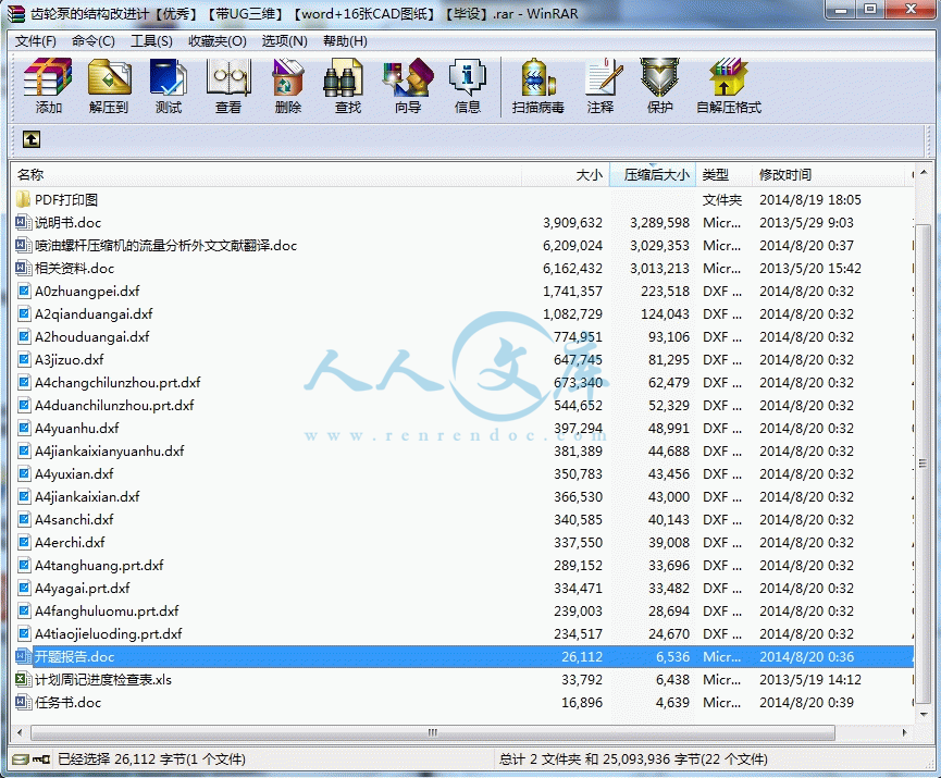
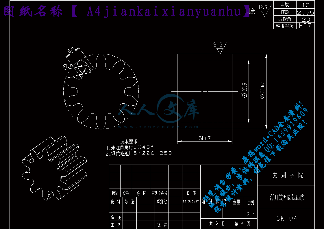
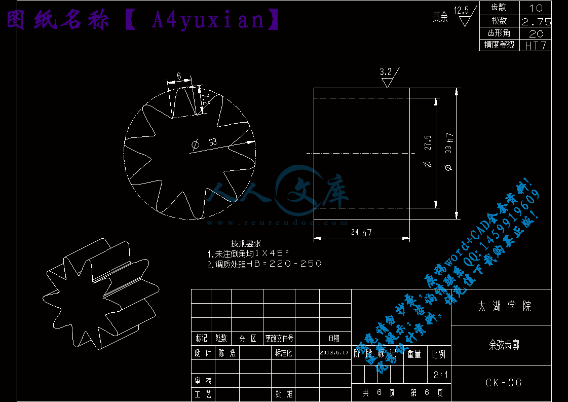
【带任务书+开题报告+外文翻译】【46页@正文17600字】【详情如下】【需要咨询购买全套设计请加QQ1459919609】.bat

A0zhuangpei.dxf

A2houduangai.dxf

A2qianduangai.dxf

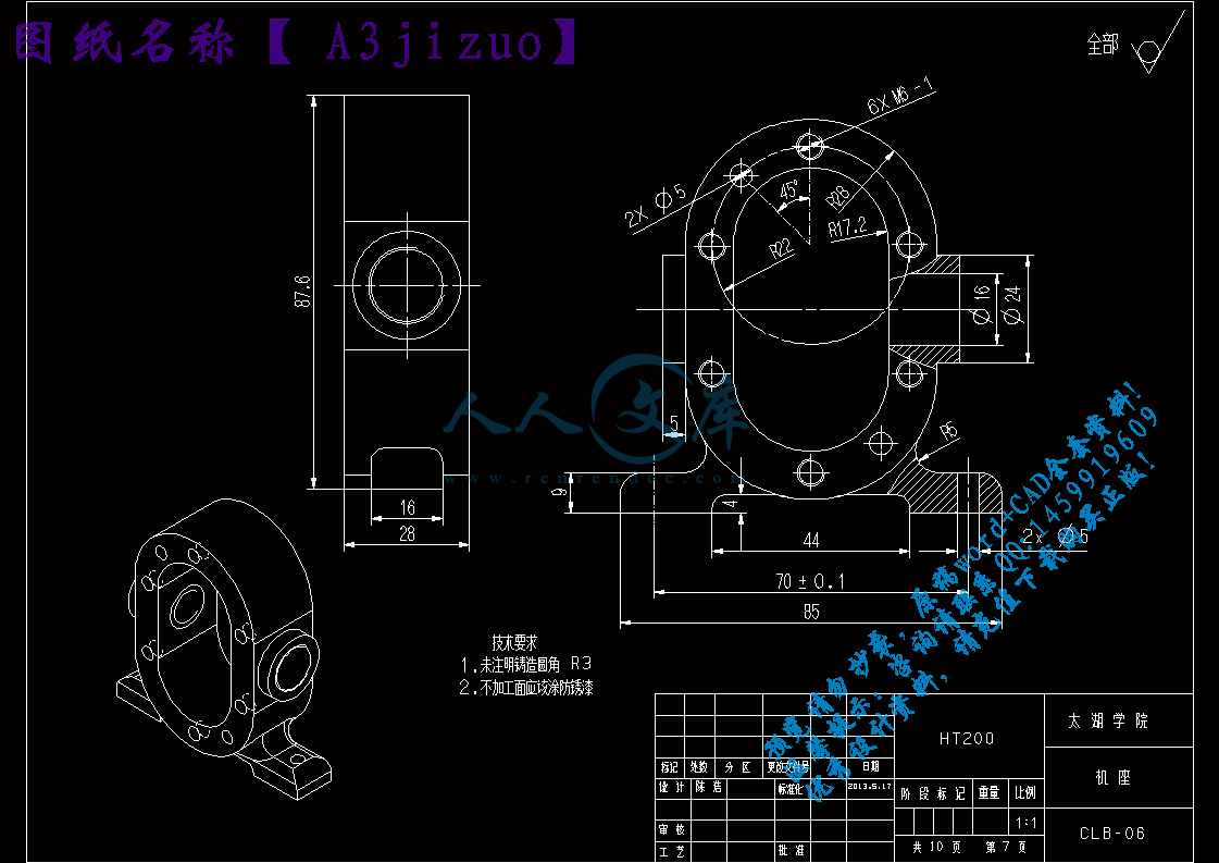
A3jizuo.dxf

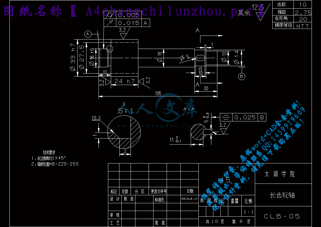
A4changchilunzhou.prt.dxf

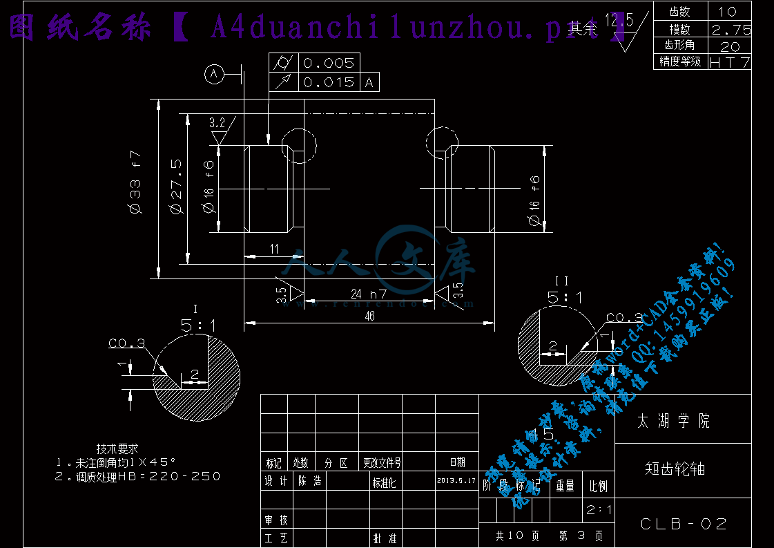
A4duanchilunzhou.prt.dxf

A4erchi.dxf

A4fanghuluomu.prt.dxf

A4jiankaixian.dxf

A4jiankaixianyuanhu.dxf

A4sanchi.dxf

A4tanghuang.prt.dxf

A4tiaojieluoding.prt.dxf

A4yagai.prt.dxf

A4yuanhu.dxf

A4yuxian.dxf

PDF打印图

ugsanweifujian

任务书.doc

喷油螺杆压缩机的流量分析外文文献翻译.doc

开题报告.doc

有限元分析资料

相关资料.doc

计划周记进度检查表.xls

说明书.doc

任 务 书

一、题目及专题:

1、题目      齿轮泵的结构改进计            

2、专题                                                

二、课题来源及选题依据

    自古以来,人类就对水运输以及提升非常重视。很早以前人类就已经发明了多种水的运输及提升工具。比如三千年前辘轳和桔槔已经在中国使用了;三千七百年前埃及的链泵也对水的运输及提升起到很大的作用;在三千三百年前,螺旋杆的诞生能将水持续不断的提升到一定高度,这种螺旋杆是由阿基米德发明出来的,同现代螺杆泵的机械原理是一样的。        

   随着工业的发展,液体运输也应用在多种多样的情况下,因此回转泵出现了。16世纪初,回转泵得到了普遍的应用,但是回转泵一直存在重大的设计缺点,比如效率低,能耗大,泄露大。直到20世纪,回转泵的各个问题才逐渐得到解决,齿轮泵就是一种典型的离心泵,其具有很多优点,比如小体积、结构简单、重量轻、容易加工,并且具有很强的自吸能力,应用范围广泛,可以适用于多种液体介质。    

三、本设计(论文或其他)应达到的要求:

① 熟悉齿轮泵的结构,及工作原理;                      

② 熟练运用UG对齿轮泵进行建模及装配;      

③ 了解并分析齿轮泵的瞬间流量、理论排量等输出特性;          

④ 研究流体动力学知识,了解并掌握FLUENT流体分析软件,并对不同齿廓类型的齿轮泵进行流体分析;                                    

⑤ 比较不同齿廓类型的齿轮泵,分析结果并优化设计出一条新的齿轮泵;

摘 要

   齿轮泵是液压系统中最重要的动力源,在液压传动系统中应用广泛, 因此, 吸引了大量学者对其进行研究,其主要部件是内部相互啮合的一对齿轮。现代机械工程对齿轮泵提出很多新要求,如压强高、排量大、脉动低、噪音低等,所以对齿轮泵的性能分析与改进成为了很重要的课题。

   本课题以齿轮泵为研究对象,总结了齿轮泵的特点,深入研究了齿轮泵整体结构及其原理,并利用UG三维建模软件对其进行实体建模,对齿轮泵的流量特征、径向啮合力进行理论分析和数值计算,为齿轮泵的设计提供必要的理论依据。研究了多种齿轮泵的齿廓类型,并推导出这些齿廓线方程。最后学习了流体动力学相关的基础理论知识,利用CFD前处理软件Gambit和后处理软件Fluent对以上五种齿廓齿轮泵进行流体分析,并比较不同齿廓分析后的结果,分别计算了齿轮泵齿间区的流量、齿轮啮合区域的流量,最后就得到了齿轮泵的流量。在时间和转速确定的情况下,得到齿轮泵的流速。外啮合齿轮泵的结构对其内部的流场有很大的影响,采用fluent有限元法求解计算模型,就不同齿廓的变化特点进行对比,可以得出每种类型齿廓的相应的优缺点,从而得出最优的分析结果并在此基础上改进设计出新的齿廓线。

   本文对齿轮泵的输出特性研究,推到出齿廓线方程,最后结合流体动力学理论,运用CFD前处理软件Gambit和后处理软件Fluent对以上五种不同的齿廓齿轮泵进行流体分析,在相同的转速下,比较不同齿廓的分析结果,渐开线齿廓在齿轮泵中的增压效果最好,并提出一些优化方案。

关键词:齿轮泵;齿廓;有限元法;输出特性;流体分析

Abstract

Gear pump is the most important source of power in the hydraulic system, widely used in the hydraulic drive system, therefore, attracted a large number of scholars study, and its main components are a pair of gears meshing with each other by the internal。Modern mechanical engineering have made ??a lot of new requirements to gear pump ,such as high pressure, large displacement, low ripple and low noise, Performance Analysis and Improvement of the gear pump has become a very important issue.

The topics to gear pump for the study, summed up the characteristics of the gear pump, in-depth study of the overall structure and principle of the gear pump and UG three-dimensional modeling software, solid modeling, the flow characteristics of the gear pump, theoretical analysis and numerical calculation of the radial direction meshing force of radial direction, to provide the necessary theoretical basis for the design of gear pump. A variety of the type tooth profile of the gear pump and derive the equations of these tooth profile. Finally learn the basic theoretical knowledge of fluid dynamics, to CFD pre-processing software Gambit and post-processing software Fluent for more than five tooth profile gear pump fluid analysis, and comparison results of different tooth profile analysis were calculated flow rate of the area of the interdental, gear meshing area of flow of the gear pumpthe, and finally got the flow of the gear pump. In the case of time and speed determined to obtain flow rate of the gear pump. Structure of the external gear pump has a great influence on its internal flow field, using the fluent finite element method for solving the calculation model, comparison of the changes in the characteristics of the different tooth profile can be drawn from the corresponding advantages and disadvantages of each type of tooth profileto arrive at the best results of the analysis to improve the design of a new tooth profile on this basis.

The output characteristics of the gear pump onto the tooth profile equation and finally the theory of fluid dynamics, the use of pre-processing of software CFD Gambit and post-processing software Fluent fluid analysis more than five different tooth profile of the gear pump in the same speed, different tooth profile analysis result of that the best of booster effect is involute line tooth profile of the gear pump, and put forward some optimization program of it.

Keywords: gear pump; tooth profile; finite element method; output characteristics;    

     fluid analysis

目录

摘 要III

AbstractIV

目录V

1 绪论1

1.1 齿轮泵的研究内容及意义1

1.2 齿轮泵国内外的发展概况1

1.3 本课题应达到的要求3

2 齿轮泵的工作原理及三维建模4

2.1 外啮合液压齿轮泵的工作原理4

2.2 齿轮泵分类、用途、应用范围4

2.2.1 齿轮泵的分类4

2.2.2 齿轮泵的用途及应用范围5

2.3 齿轮泵的三维建模5

3 齿轮泵的流量特性8

3.1 齿轮泵流量的研究8

3.1.1 齿轮泵平均流量10

3.1.2 齿轮泵瞬态流量10

3.2 齿轮泵排量的研究11

3.2.1 根据齿槽有效容积的排量计算方法11

3.2.2 根据轮齿有效体积的排量计算方法12

3.3 本章小结13

4 流体动力学理论知识研究14

4.1 流体力学简介14

4.2 流体动力学的基本思想14

4.3 计算流体动力学的特点15

4.4 计算流体力学的基本步骤15

4.5 流体力学基本方程17

4.6 流体流动模型的确定19

4.7 一般结构19

4.7.1 前处理19

4.7.2 求解器19

4.7.3 后处理19

4.8 本章小结19

5 齿轮泵不同齿廓的流体动力学分析20

5.1 Fluent简介20

5.2 齿轮泵的流体力学分析20

5.2.1 建立流体模型20

5.2.2 划分流体模型的网格20

5.2.3 设置流体模型的边界条件20

5.3 齿轮泵不同齿廓的流体分析21

5.3.1 渐开线齿廓齿轮泵的流体分析21

5.3.2 余弦齿廓齿轮泵的流体分析23

5.3.3 圆弧齿廓齿轮泵的流体分析26

5.3.4 三齿摆线齿廓齿轮泵的流体分析29

5.3.5 二齿摆线齿廓齿轮泵的流体分析32

5.4 齿轮泵的结构改进设计36

5.4.1 齿轮泵齿廓的改进36

5.5 本章小结39

6  结论与展望40

6.1 课题总结40

6.2 课题展望40

致谢41

参考文献42

1 绪论

1.1 齿轮泵的研究内容及意义

在21世纪,节约能源使我们亘古不变的话题,在工业中也一直提倡能源的节约,动力源是液压系统中最重要的部分,这个动力源也包含齿轮泵,所以我们要对齿轮泵的齿轮优化设计,以达到提高齿轮泵的效率和节约能源的问题,最主要的部件是内部相啮合的一对齿轮,在结构上可分为内啮合齿轮泵和外啮合齿轮泵两大类。由于它具有结构简单、加工方便、体积小、自吸能力强且重量轻等特点,使它在机械、国防、能源、冶金、交通、石化、轻工、食品等领域得到广泛的应用。现在齿轮泵的制造已经很成熟,我们可以对齿廓加已修理,对齿轮泵进行改良设计,所以齿轮的工作原理我们是必须要掌握的,然后利用相关CAD/CAM软件建立计算机实体模型,借助有限元分析法进行详细的受力和变形分析,依据机构运动分析法进行实际的动作仿真,并将根据分析和仿真结果指导该齿轮装置进行修正,结合现代自动控制理论对齿轮装置进行有效的控制,最后尽可能考虑装置和有关零部件的标准化和参数化。优化好齿轮后,效率就能提高,从而可以节约能源。当大家在倡导可持续发展的时候,节约能源就变得越来越重要了。随着技术的不断进步,齿轮泵产品必将向环保、节能、智能化方向发展。

1.2 齿轮泵国内外的发展概况

由于我国工业基础溥弱,齿轮油泵行业起步较慢,但其发展速度比较快。齿轮油泵在发展的过程中,存在相当严重的问题。综合多方面原因,陈列出如下几条:1、国家缺乏对机械基础件齿轮油泵行业有力的政策支持;2、企业基础薄弱:机械基础件行业基础差,底子薄,科技投入少,开发力量薄弱;经由二十余年消化吸收国外提高前辈技术以及自主立异。我国齿轮油泵设备制造行业有了奔腾发展。

齿轮油泵的进一步发展得靠多方面的支持,国家政策的支持,科研技术的大量投入,机械基础件工艺行业的提高等等。

齿轮油泵行业2010年全国业标准化发展规划,齿轮油泵全国协会提出了全面建设小康社会的宏伟目标,明确了21世纪前20年我国经济建设和改革的主要任务。“十一五”时期,是全面建设小康社会承前启后的关键时期,“十一五”规划,是全面建设小康社会的第一个五年规划。标准作为经济建设和行业发展的技术支撑,是“十一五”规划不可缺少的重要组成部分,是指导生产、实施产业政策、行业规划、规范市场秩序、进行宏观调控和市场准入的重要基础。为此,根据机械科学研究院的要求,特编制“十一五”全国泵行业标准化发展规划。

齿轮油泵行业及其产业基本情况概述

1、齿轮油泵行业及其主要产业的内涵和构成齿轮油泵行业主要由生产各类离心油泵、重油煤焦油泵,渣油泵,导热油泵,自吸油泵、输油泵、旋涡泵、回转式容积泵、往复式容积泵和水环真空泵等企业构成。在这些泵类产品中,按台份计,离心泵约占接近70%,回转式容积泵和往复式容积泵约占18%。全国具有一定规模的泵制造厂约有2000家,产品种类约有450个系列,5000多个品种。2002年统计,在这些泵制造厂中,较大的699家泵制造厂共生产2663万台,总产值约为208亿元。这些泵被广泛用于国民经济各部门,基本满足了我国经济发展对泵的需要,其中也包括具备为各种大型成套装置提供配套用泵的能力。

据不完全统计,约有21%的电机用于驱动各类泵,在能源中约有近五分之一的能源用于驱动各类泵。在火电和核电业中,泵已成为最重要的辅机,在石化业中泵已成为重要的设备之一,泵在通用机械中已成为最量大面广的产品,已经成为装备制造业重要的装置之一。

2、国外齿轮油泵行业及其主要产业发展现状和发展趋势

世界泵业一直在不断发展,近几年的增长率平均4.5%左右,2002年泵业产值约270亿美元,约有近万家制造厂,其中10大家泵制造厂的产值约占世界泵业总产值的31%。这10家泵制造厂中,美国4家,德国2家,日本、英国、丹麦、瑞士各1家。

世界泵业的发展趋势:(1)竞争和垄断进一步加剧,跨国齿轮油泵业公司的垄断势头进一步加剧。如世界泵业最大的前五家泵制造厂垄断着世界泵业总产值22%。世界泵业中的一些主要制造厂的制造技术已达到相当成熟和完善的水平,其产品有极高的知名度,在特定的领域中有很高的市场占有率;(2)世界齿轮油泵业中泵制造厂家数量会不断减少,自2000年以来,世界泵业已有80起大的合并和收购,通过这种集团化的合作发展战略,不仅可以得到最大的经济规模,还有利于利用原来的商标和知名度,实现持续发展;(3)世界齿轮油泵业会持续发展,预计今后3~5年中,世界齿轮油泵业将会以每年5.5左右的增长率发展;(4)不断开拓新的市场范围和领域,中国加入WTO后,世界各大泵制造厂都非常关注中国的用泵市场,世界泵业前20家制造厂绝大多数都准备或已经在中国建制造分厂。

3、国内泵行业及其主要产业现状和发展趋势

泵行业现状:(1)通过执行国家提出的“以市场换技术”合作生产的方式,使我国泵业中具有极高技术水平的关键用泵的技术水平与国外发达国家的同类泵产品水平接近;(2)近几年,齿轮油泵类产品的产值皆以11%~12%的速率发展;(3)股份制和民营制造厂在我国泵业中占主导地位;(4)齿轮油泵制造厂都在进行产品结构调整和技术改造,企业都在做强、做大,每年新增泵制造厂的数量明显减少;(5)市场竞争更激烈,齿轮油泵产品中的普通泵供大于求的局面没有改变,单台泵的利润率在逐年降低。由于材料涨价等因素影响,泵制造厂的利润增长率明显降低。

发展趋势:(1)由于执行“以市场换技术合作生产”的方式,关键用泵,如:百万级核电用泵、火电用泵、大型输水泵,近几年会快速增长;(2)在经济全球化、市场国际化形势的影响下,对贯彻国际标准和执行国外先进标准的意识会强烈和自觉;(3)随着我国装备制造业的快速发展,我国泵业还会以高出我国机械工业增长速度2-3%的速度持续发展;(4)泵制造厂的合并和联合必然增多,向集团化发展是趋势。今后我国的泵制造厂的数量将逐年减少;(5)我国2002年出口齿轮油泵为4.73亿美元(同年进口泵为7.76亿美元),今后几年出口泵会明显增加,尤其是通用泵的出口量会更快增加。

1.3 本课题应达到的要求

对齿轮泵的结构及基本原理有简单了解。

运用UG软件完成设计工作,对产品进行造型、结构设计,在设计阶段完成传统的设计方法,分析齿轮泵的流量特性,了解流量对齿轮泵的影响。运用Gambit和Fluent软件对齿轮泵的不同齿廓主动件和从动件进行流体分析,得出压力图和速度图,分析比较结果,选择一条在综合性能上都比较好的齿廓,并在其基础上改进设计出一条新的齿廓,以达到提高齿轮泵效率的功效。

参考文献

[1]  王军.加压溶气气浮法浮选微细颗粒的理论分析[J] .矿业工程,2005,37-39.

[2]  吉卫喜.机械制造技术基础[M].高等教育出版社,2008-6

[3]  冷如波.高压注水泵动力学仿真分析[J] .系统仿真学报,2005 (12): 2 863-2 868.

[4]  范明豪.复合齿轮泵基础理论研究[D] .安徽:淮南工业学院,1999

[5]  张军.平衡式复合齿轮泵的有限元分析[J] .煤矿机械,2007 (10): 66-67

[6] 阎 超.计算流体力学方法及应用[M] .北京航天航空大学出版社,2006:

[7] 王和顺、陈次昌、王金诺.干气密封端面流场的数值模拟.西南交通大学学报,2007 42(5):568-573

[8]  栾振辉.齿轮泵研究的现状与发展 [J].起重运输机械, 2005:(6):11-13.

[9] 江帆,黄鹏.Fluent 高级应用与实例分析[M].北京:清华大学出版社,2008:205-208.

[10] 王和顺,陈次昌,王金诺.干气密封端面流场的数值模拟 [J].西南交通大学学报,2007,42(5):568-573.

[11]  江帆,陈维平,李元元等.润滑用齿轮泵内部流场的动态模拟.现代制造工程,2007(6)

[12]  江帆,黄鹏.Fluent高级应用与实例分析[M]. 北京:清华大学出版社,2008

[13] 蔡立新.影响齿轮泵寿命的因素分析[J].电机化, 2002(2):25.

[14] 姜继海.液压传动[M].13版.哈尔滨:哈尔滨工业大学出版社,2006:45-491.

[15] 胡小康.UGNX6运动仿真培训教程[M].清华大学出版社,2009-10

[16] 唐金松.简明机械设计手册[M].上海科学技术出版社,2000-10[17] 朱孝录.齿轮传动设计手册[M].化学工业出版社,2010-4

[18] 熊小艳.同步齿轮泵的优化设计及基础理论研究.安徽理工大学,2009.

[19] 姜继海.液压传动[M].哈尔滨:哈尔滨工业大学出版社,2006

[20] James Sullivan."Fluid Power, Theory and Applications, 4thEd".Prentice-Hall. 1998.

[21] aroslav Ivantysyn and Monika Ivantysynova. "Hydrostatic Pumpsand Motors", Tbi, 2003.

[22] RoquetP,Enhanced design of high pressure gear pumps using environmen-tally acceptable hydraulic              fluids,ECOPUMP,BRITE- EURAMprojectBE-95- 1046, 1998.

[23] Castilla R,Gamez-MonteroPJ, CodinaE. Turbulence in internal flowsin minihydraulic components. CIMNE,2005:241- 51.

[24] Yogendra Panta."Numerical Flow Analysis

内容简介:
无锡太湖学院毕业设计(论文)外文资料翻译 信机 系 机械工程及自动化 专业院 (系): 信 机 系 专 业: 机械工程及自动化 班 级: 机械97 姓 名: 陈 浩 学 号: 0923807 外文出处: 机械专业英语教程 附 件: 1.译文;2.原文;3.评分表 2013年5月20日 英文原文4.3 Flow in an Oil Injected Screw CompressorFigure 4-27 Comparison of pressure change for turbulent and laminar flow calculationsThe difference in the compressor flow obtained from laminar and turbulent calcu-lations is presented in Figure 4-28. The mass flows at suction and discharge are given as functions of the shaft angle. On average, 4% higher low is calculated with the turbulent model. The difference was greater at the discharge end of the compressor, both in the mean value and in the amplitude. This agrees with the re-sults obtained from the approximate calculations where turbulent transport through clearances is significant. The difference in flow obtained at the suction end is, on average, less than 3%. This shows that a compressor with a large suc-tion opening has no significant dynamical losses, although turbulence exists in the compressor low pressure domains. It is expected that the difference between the laminar and turbulent flow calculations will be smaller for higher discharge pres-sures and lower compressor speeds.Figure 4-28 Comparison of fluid flow at inlet and exit of screw compressorThe integral parameters obtained from both the laminar and turbulent numerical models are presented in Table 4-2. According to these results, it can be concluded that turbulence has some influence on the screw compressor. Its effect is greater at lower pressure ratios and low compressor speeds.More detailed insights into the results obtained from the k-model of turbulence can be found in the following four figures; Figure 4-29 shows the kinetic energy of turbulence. The dissipation rate is presented in Figure 4-30, the turbulent vis-cosity in Figure 4-31 and the dimensionless distance from wall y+ is given in Figure 4-32.Figure 4-29 Kinetic energy of turbulence within the screw compressor4.3 Flow in an Oil Injected Screw Compressor Figure 4-30 Dissipation rate within the screw compressorFigure 4-31 Turbulent viscosity within the screw compressorFigure 4-32 Dimensionless distances from the wall within the compressorThe results in all these diagrams are presented in horizontal sections through the blow hole areas on the suction and discharge side of the compressor, in vertical sections through the rotor axes and in cross sections at suction and discharge. The kinetic energy of turbulence, dissipation, turbulent viscosity and y+ are all high for the lobes exposed to the suction domains. All these gradually die out towards discharge. The dissipation rate is extremely high in the clearance gaps between the rotors, as shown in Figure 4-30, while in the other domains it is significantly lower. On the other hand, y+ is small in the clearance gaps while in the main do-mains at suction it has higher values, as shown in Figure 4-32.4.3.5 The Influence of the Mesh Size on Calculation AccuracyMost calculations in this book are presented for numerical meshes with an average number of 30 cells along one interlobe and a similar number of time steps selected for the rotor to rotate between two interlobe positions. The numerical mesh for thecompressor in this example consists of about 450,000 cells of which About 322,000 numerical cells define the rotor domains. This was a convenient numberof cells to use with a PC computer with an ATHLON 800 processor and 1GB of RAM, which was used for this study. Although the results obtained on that mesh appeared to be satisfactory and agreed well with the experimental data, an investi-gation of the influence of the mesh size on the calculation accuracy had to be con-ducted. For that reason, two additional meshes were generated for the same com-pressor. A smaller one was generated with 20 points along the rotor interlobe, which gave 190,000 cells on both rotors while the other compressor parts were mapped with almost the same number of cells as originally. The overall number of numerical cells was about 353,000. A lower number of cells on the rotors results in a geometry, which does not follow the rotor shape precisely, and the intercon-nection between rotors would possibly become inappropriate. This number of nu-merical cells is probably the lowest for which reliable results can be obtained. Thelargest numerical mesh generated for this investigation consists of 45 numerical cells along the rotor interlobe. That gave 515,520 cell on the rotors and 637,000 cells for the entire compressor domain. This was the biggest numerical mesh that could be loaded into the available computer memory without disc swapping dur-ing the solution. These three numerical meshes are presented in Figure 4-33 in the cross section perpendicular to the rotor axes.Figure 4-33 Three different mesh sizes for the same compressorThe results of the calculations are presented in Figure 4-34 in the form of a pres-sure-angle diagram, and in Figure 4-36 as a discharge flow-angle diagram. The first diagram shows how the calculated working pressures for all three investi-gated mesh sizes agree with the measurements. The lowest number of cells gives the highest pressure in the working chamber and vice versa. As a result of that, the consumed power is changed slightly, from 42 kW obtained with the smallest mesh to slightly less then 41 kW for the largest mesh. The difference between the two is less then 3%. This situation is shown in Figure 4-35. The diagram shows the larg-est difference within the cycle to be in the discharge area of the compressor. Some difference is also visible in the middle area of the diagram which seems to be a consequence of the leakage flows obtained with smaller meshes between the ro-tors. In that area, the mesh is probably too coarse to capture all the oscillations which appear in the flow.Figure 4-34 P-alpha diagrams for three different mesh sizesFigure 4-35 Compressor power calculated with three different mesh sizes4.3 Flow in an Oil Injected Screw CompressorFigure 4-36 Discharge flow rates for different mesh sizesFigure 4-37 Integral flow rate and Specific power obtained with different mesh sizesDiagrams of discharge flow as a function of rotation angle are given in Figure4-36. The coarser mesh shows less oscillation in the flow then the finer meshes. However, the mean value of the flow remained the same for all three mesh sizes, as shown in Figure 4-37. Specific power is calculated from the values obtained previously. It shows a slight fall in value as the number of computational cells is increased.The results obtained with the three different mesh sizes for the compressor in-vestigated here give the impression that the calculation conducted for the com-pressor on an average size of the mesh with 25 to 30 numerical cells along the ro-tor interlobe is sufficiently accurate.中文译文4.3 喷油螺杆压缩机的流量图4-27计算比较湍流和层流压力变化如图4-28为在计算吸气和排气的质量流量功能轴角中获得的压缩机流从层流和湍流差异。总体而言,湍流模型比流从层流高4%,无论是在平均值和振幅,压缩机的排出端是最大的,通过计算近似结果获得间隙显着的湍流输送的重。在吸入端获得的流量差异的平均值,小于3。这表明,具有大的吸入端的压缩机吸气开口没有任何显着的动力损失,虽然在压缩机低压域存在湍流。这是预期的层流和湍流之间的差异计算将提高排气压力和减小压缩机速度。图4-28根据流体的流动比较螺杆式压缩机的入口和出口从层流和湍流数值模型的积分获得的参数,如表4-2中。根据这些结果,可以得出结论,在湍流的螺杆式压缩机上有一定的影响。其效果是在压力越小,流速越大。从第k湍流模型获得的结果的更详细的分析,可以发现在以下四个数字,如图4-29的湍流的动能。图4-30,图4-31动荡对粘度和无量纲距离墙Y +耗散率,如图4-32。图4-29螺杆压缩机内的湍流动能图4-30螺杆式压缩机内的损耗率图4-31螺杆压缩机内的湍流粘度图4-32从墙壁内压缩机的量纲距离通过吸入阀和排出侧的压缩机的结果列于所有这些图中,在通过转子轴的吸入阀和排出的横截面的垂直剖面上的吹孔区域的水平部分。动荡,耗散,湍流粘度和y+的动能都是高暴露在吸域叶上,所有这些逐渐消亡走向放电。耗散率非常高,转子之间的间隙差距,如图4-30所示,而在其他领域,它是显着较低。另一方面,如图4-32所示,+小的间隙中,在主电源处于吸入它具有较高的值。 4.3.5 网格大小对计算精度的影响在计算这本书中的大部分平均30个细胞的数量沿一个和类似用于转子之间旋转两位置的数量的选择步骤啮合。在这个例子中包括约45万个细胞数值网格,其中约322,000数字单元格定义转子域。这是用于这项研究为了方便使用的细胞数量与PC电脑的Athlon800处理器和1GB的RAM,虽然网格上,得到的结果似乎是令人满意的,并与实验数据相同,但在康秀红,杜强,李殿中,李依依的调查中,影响网格尺寸的计算精度的到的结果是可靠的。本次调查由45个数字单元格沿转子的数值t网。这给了整个压缩机515,520细胞转子和637,000细胞领域。这是最大的数值的网格,可以在装入光盘交换过程中溶液没有可用的计算机内存。图4-33中介绍这在转子轴垂直的截面中的三个数值的啮合。图4-37获得不同的网目尺寸和比功率的积分流量。图36中给出的是作为旋转角度的函数的排出流,粗网格显示振荡流,
温馨提示:
1: 本站所有资源如无特殊说明,都需要本地电脑安装OFFICE2007和PDF阅读器。图纸软件为CAD,CAXA,PROE,UG,SolidWorks等.压缩文件请下载最新的WinRAR软件解压。
2: 本站的文档不包含任何第三方提供的附件图纸等,如果需要附件,请联系上传者。文件的所有权益归上传用户所有。
3.本站RAR压缩包中若带图纸,网页内容里面会有图纸预览,若没有图纸预览就没有图纸。
4. 未经权益所有人同意不得将文件中的内容挪作商业或盈利用途。
5. 人人文库网仅提供信息存储空间,仅对用户上传内容的表现方式做保护处理,对用户上传分享的文档内容本身不做任何修改或编辑,并不能对任何下载内容负责。
6. 下载文件中如有侵权或不适当内容,请与我们联系,我们立即纠正。
7. 本站不保证下载资源的准确性、安全性和完整性, 同时也不承担用户因使用这些下载资源对自己和他人造成任何形式的伤害或损失。
提示  人人文库网所有资源均是用户自行上传分享,仅供网友学习交流,未经上传用户书面授权,请勿作他用。
关于本文
本文标题:齿轮泵的结构改进计【优秀】【带UG三维】【word+16张CAD图纸】【毕设】
链接地址:https://www.renrendoc.com/p-313918.html

官方联系方式

2:不支持迅雷下载,请使用浏览器下载   
3:不支持QQ浏览器下载,请用其他浏览器   
4:下载后的文档和图纸-无水印   
5:文档经过压缩,下载后原文更清晰   
关于我们 - 网站声明 - 网站地图 - 资源地图 - 友情链接 - 网站客服 - 联系我们

网站客服QQ:2881952447     

copyright@ 2020-2025  renrendoc.com 人人文库版权所有   联系电话:400-852-1180

备案号:蜀ICP备2022000484号-2       经营许可证: 川B2-20220663       公网安备川公网安备: 51019002004831号

本站为文档C2C交易模式,即用户上传的文档直接被用户下载,本站只是中间服务平台,本站所有文档下载所得的收益归上传人(含作者)所有。人人文库网仅提供信息存储空间,仅对用户上传内容的表现方式做保护处理,对上载内容本身不做任何修改或编辑。若文档所含内容侵犯了您的版权或隐私,请立即通知人人文库网,我们立即给予删除!