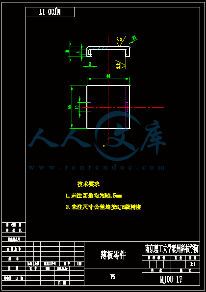
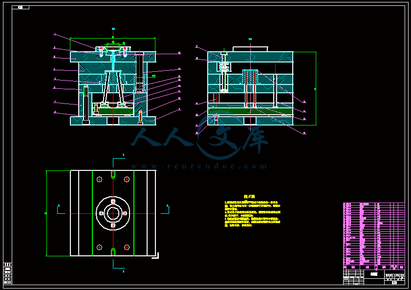
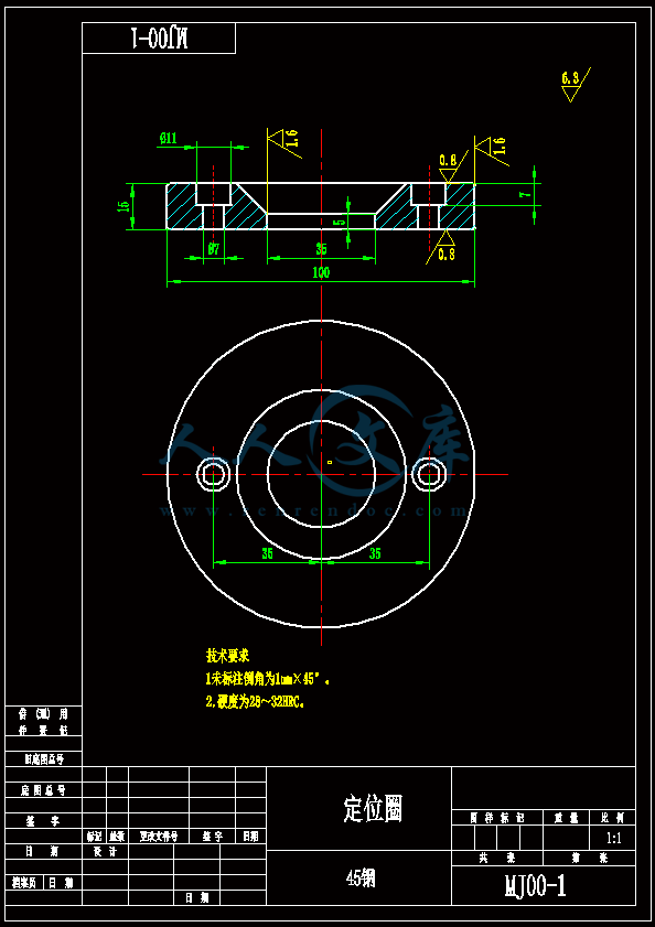
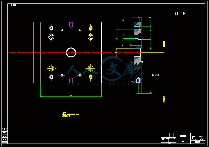
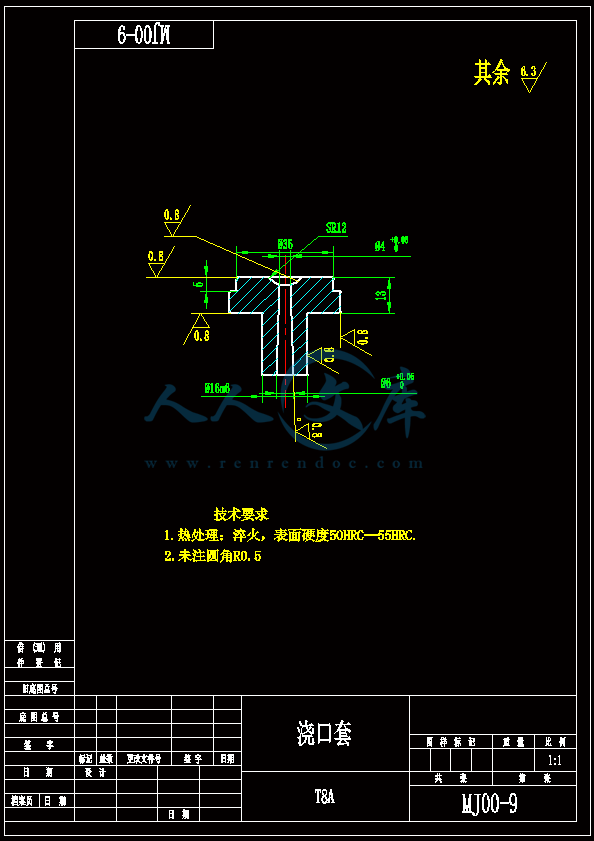
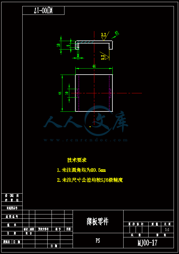
薄板零件带内侧抽芯机构的注射模具的设计【一模一腔】【含CAD图纸、说明书】
收藏
资源目录

压缩包内文档预览:
编号:31702878
类型:共享资源
大小:1.60MB
格式:ZIP
上传时间:2019-12-10
上传人:机****料
认证信息
个人认证
高**(实名认证)
河南
IP属地:河南
50
积分
- 关 键 词:
-
一模一腔
含CAD图纸、说明书
薄板
零件
内侧
机构
注射
模具
设计
CAD
图纸
说明书
- 资源描述:
-
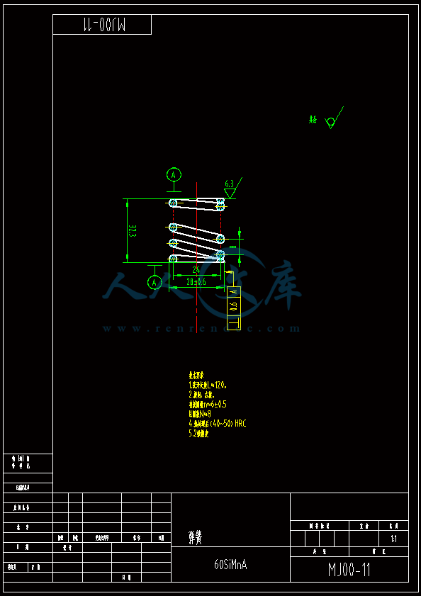
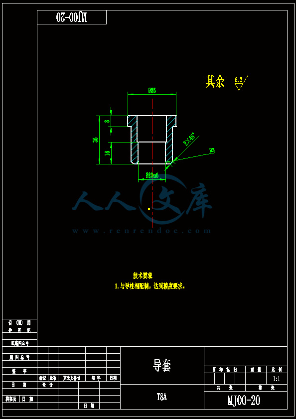
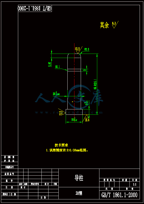
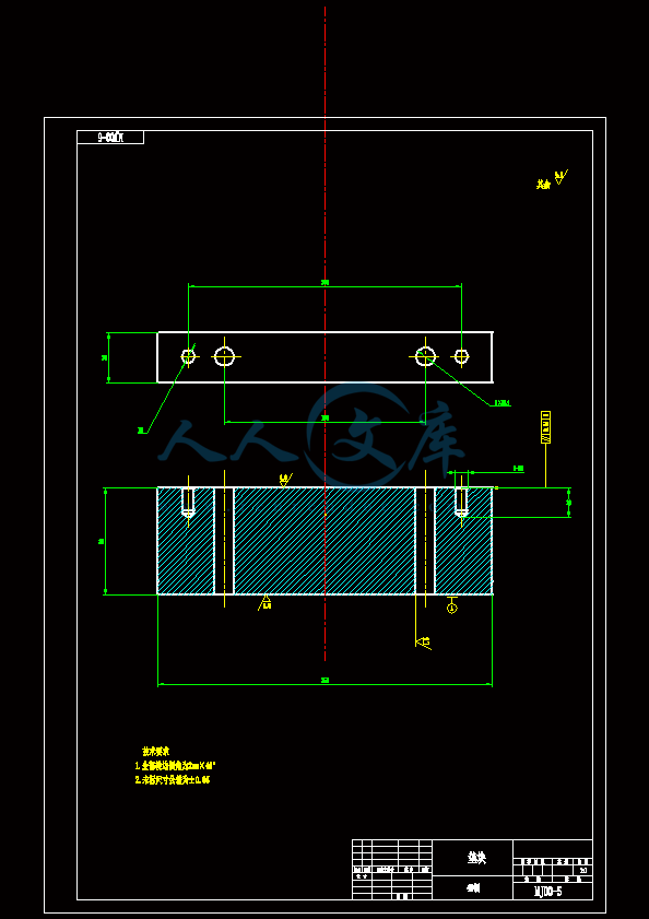
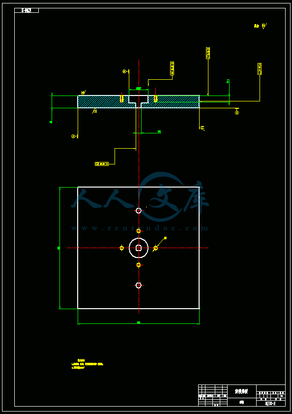
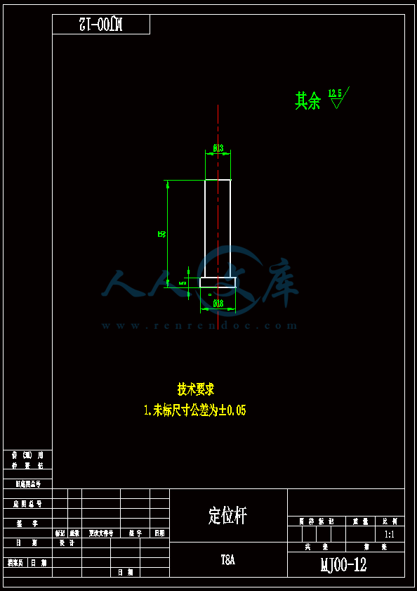
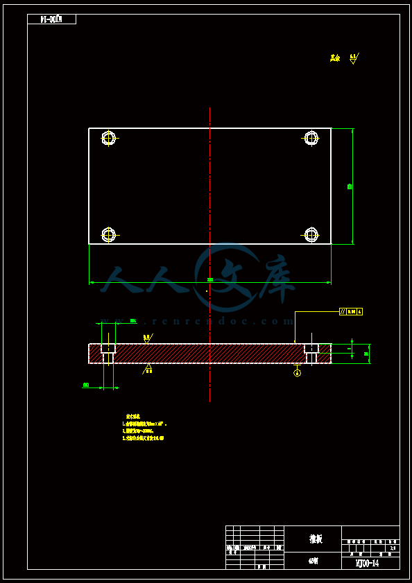
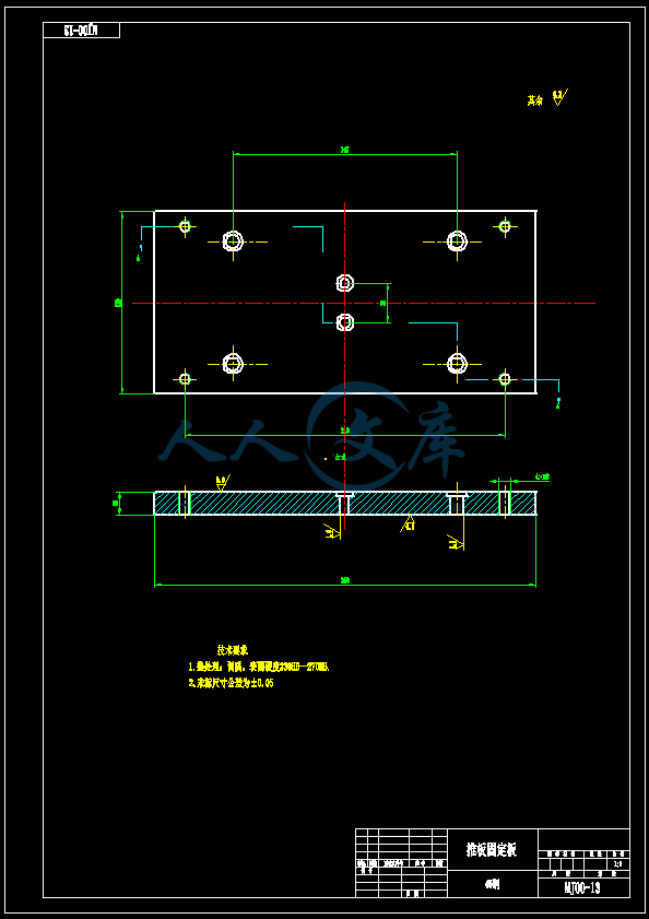
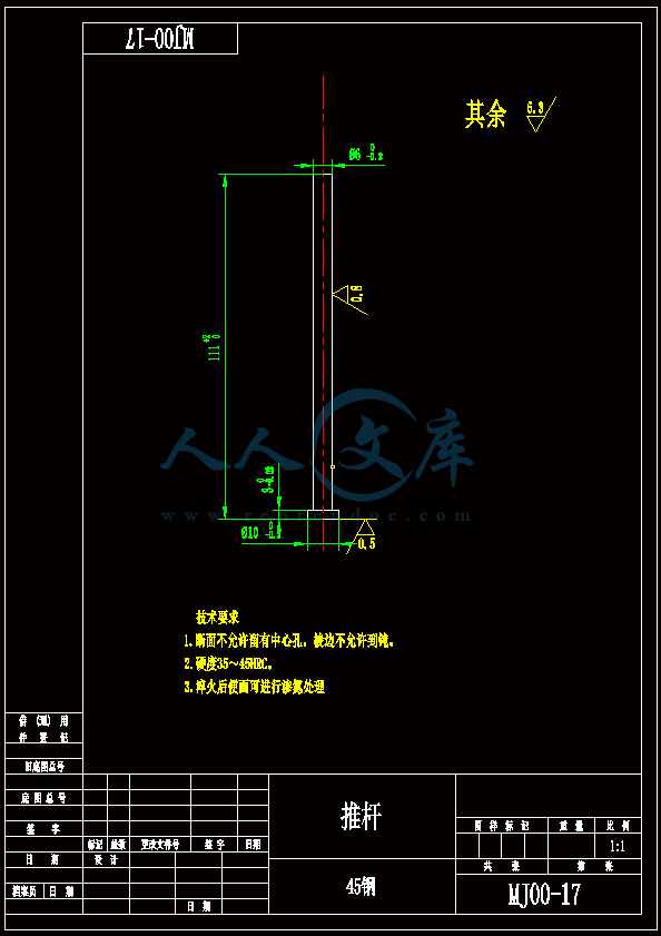
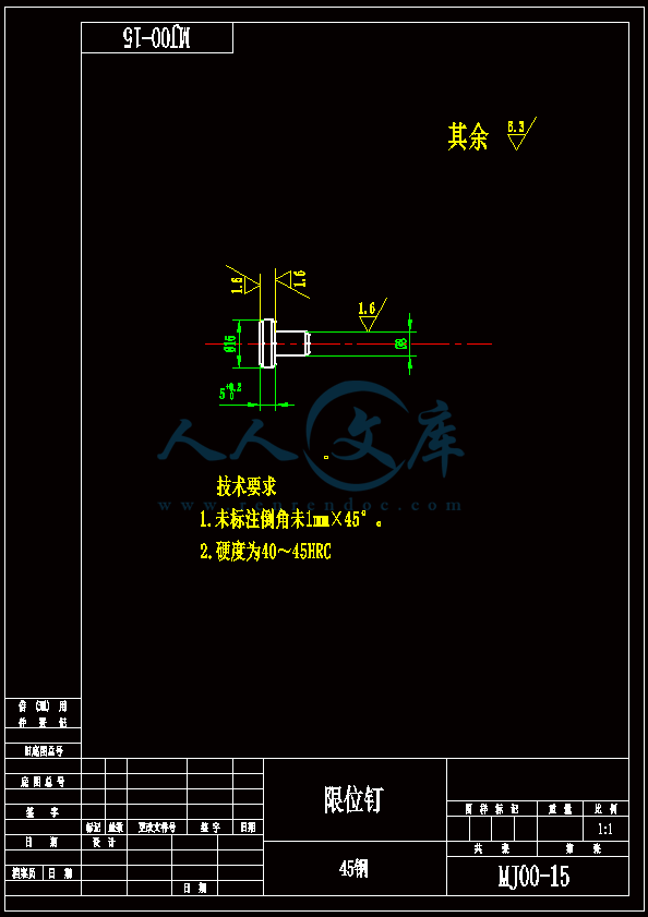
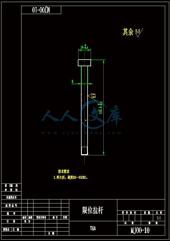
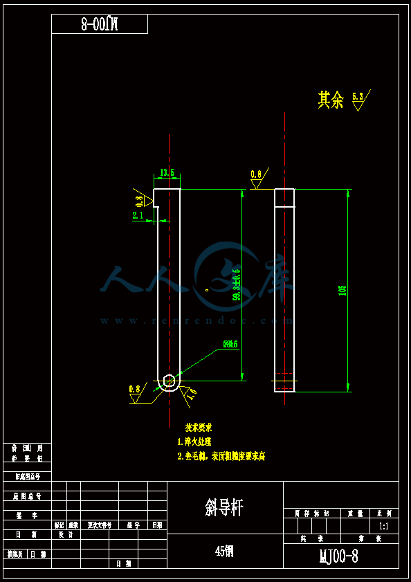
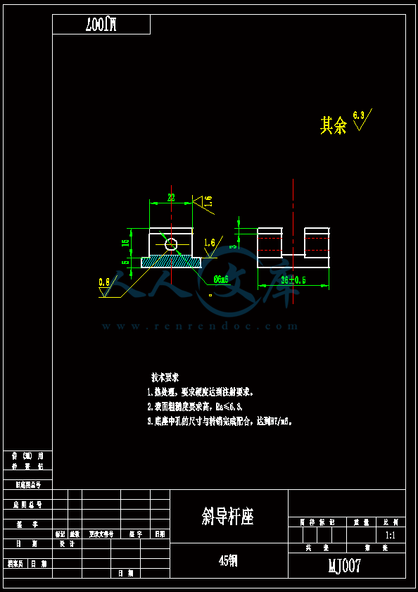
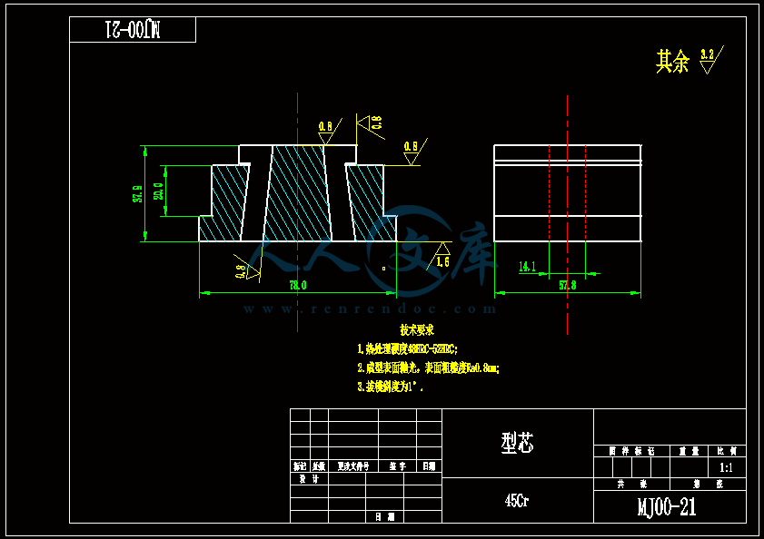
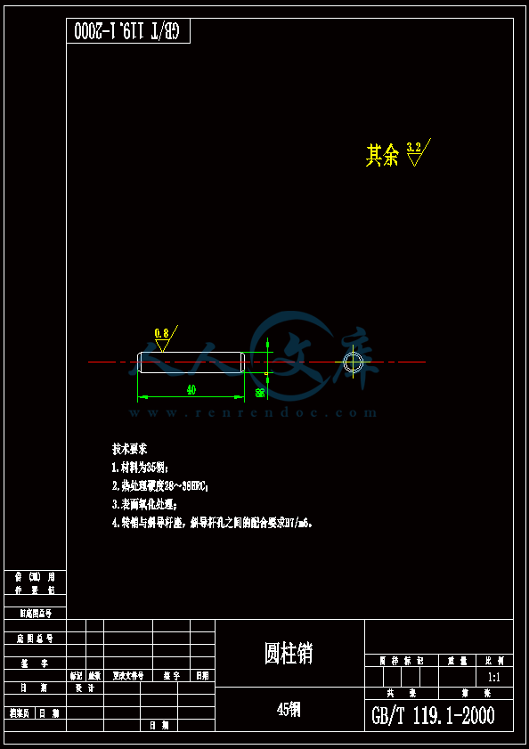
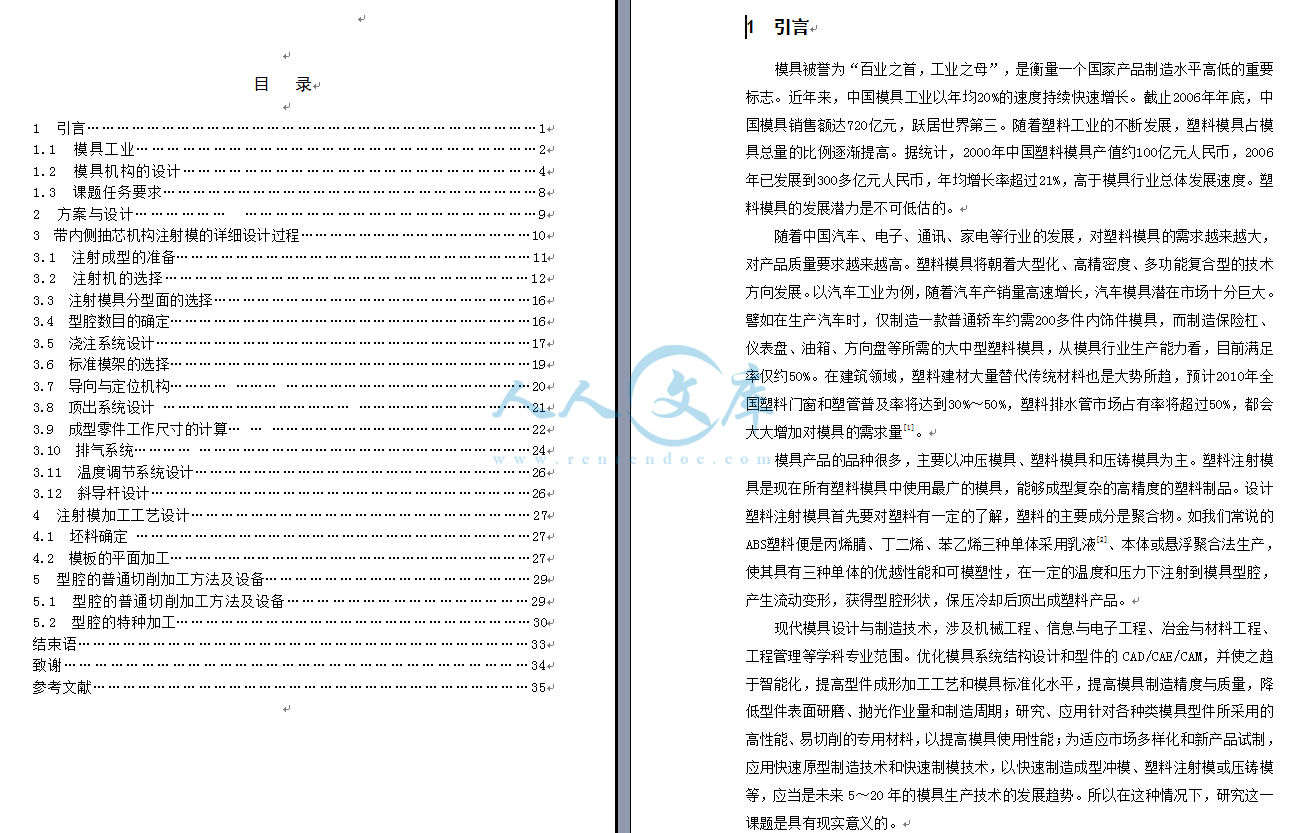
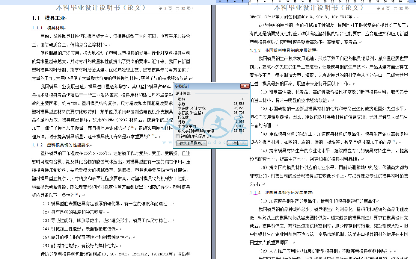
【温馨提示】压缩包内含CAD图有下方大图片预览,下拉即可直观呈现眼前查看、尽收眼底纵观。打包内容里dwg后缀的文件为CAD图,可编辑,无水印,高清图,压缩包内文档可直接点开预览,需要原稿请自助充值下载,所见才能所得,请见压缩包内的文件及下方预览,请细心查看有疑问可以咨询QQ:11970985或197216396

- 内容简介:
-
毕业设计(论文)外文资料翻译系部: 机械工程系 专 业: 机械工程及自动化 姓 名: 学 号: 外文出处: Journal of Engieering Materials and Technology 附 件: 1.外文资料翻译译文;2.外文原文。 指导教师评语:译文基本能表达原文思想,语句较流畅,条理较清晰,专业用语翻译基本准确,基本符合中文习惯,整体翻译质量一般。 签名: 年 月 日附件1:外文资料翻译译文 加强使用粘结剂力轨迹和神经网络控制获得一致的最小回弹曹健 Brad Kinsey机械工程系,西北大学,埃文斯顿,IL 60208Sara A. Solla物理和天文学系,西北大学,埃文斯顿,IL 60208;生理学系,西北大学医学院,芝加哥,IL 60611 制造钣金属片面临的最大挑战之一是要取得一致的回弹量。回弹,当工件加工撤掉后,弹性材料恢复,主要的原因是最后一部分的几何变化的不一致。由于非线性效应,相互作用过程和材料参数的关系,要获得一致可取的回弹量是极其困难。在本文中,回弹量在模拟通道的形成过程证明了神经网络系统的独特的能力同时加上加强粘结剂力轨迹控制回弹角和最大主应变量起的作用。当面临着很大差异甚至在材料性能,板度,摩擦条件下,我们的控制系统将会制作出零件最终的形状。导言在当今竞争激烈的制造业中零件获得一致准确的尺寸是至关重要的。不一致的零件尺寸会延缓新产品的开发,增加转换时间,使后续开发生产困难,还需要额外的保证工序质量,同时还降低客户对终端产品的满意度和信任度。在金属板料成形过程中,回弹方面的材料是保证零件最终精确的一个主要因素。回弹是在其满载的条件下几何的差额部分,例如,符合工件的几何形状,当局部已卸下,自由的状态,几何之间的差额。对于一个复杂的三维零件,不必要的扭曲是另一种形式的回弹。薄板厚度方向中压力分布不一致和冲压加载放宽和卸载过程中,其结果是产生回弹。影响回弹的因素包括变化过程和材料参数,如摩擦条件下,工件的几何形状,材料性能,板的厚度,以及模具温度。由于在制造过程中控制所有这些变数是几乎不可能的,反过来证明回弹是不能随时控制。回弹是一个高度非线性效应,这个新增加的困难是事实,因此,模拟和纠正的方法是复杂的。最近几年出现了许多研究有关回弹,例如,汽车工程师学会,NUMIFORM和NUMISHEET会议。通过修改形成过程可减少回弹。一些研究人员提出了使用加强粘结剂力轨迹以实现这一目标(Ayres,1984;Hishida and Wagoner, 1993; Sunseri et al., 1996)。进一步加强粘结剂力轨迹是一个瞬时跳跃从低粘结力(LBF)到高粘合剂力(HBF),在指定的百分比总额的冲压位移(PD)(参阅图1)。Sunseri et al. (1996),调查铝通道形成过程的回弹,图2所示。他们的工作是通过模拟实验明确形成过程和材料参数用处。在生产环境中,可是,由于不同的进程回弹量将偏离所期望的水平。因此,控制系统,可变化的工艺参数要求近年来,许多研究小组调查了利用人工神经网络系统来控制金属板料成形过程。由于非线性效应和相互作用的过程参数金属成型是an ideal candidate,神经网络系统控制。(Cho et al. (1997)采用了神经网络预测的力量在冷轧和,(Di and Thomson(1997)预测起皱限制正方米板材下角的紧拉应力。除此之外,(Elkins, 1994 and Yang et al., 1992), Forcellese et al. (1997)采用了神经网络系统控制60度铝V型冲压空气弯曲回弹的进程。他们的系统利用实验获得的例子组成的5个参数从力冲压轨迹,离线测量板厚,神经网络目标弯曲角度的投入和冲压的移位的输出。在另一项研究项目,Ruffini and Cao(1998)建议采用神经网络控制回弹角的渠道的形成过程与轨迹冲压力作为唯一的来源,确定工艺变化和调整的HBF,Sunseri et al. (1996)。初步结果表明这种方法是很有希望的。 本文中,铝渠道的回弹是通过加强控制粘结剂力轨迹和神经网络控制。神经网络确定了HBF和PD的粘结剂力轨迹。冲床力轨迹被确定为关键参数的变化,反映在材料性能,板的厚度,还有摩擦系数。因此,四个多项式系数从曲线拟合的冲压力轨迹被用来作为投入的神经网络系统。图3显示流程图的控制系统提出这一点应用。尽管材料性能有着很大差异,板厚度(T),和摩擦系数(m),回弹角()之间保持了0.2和0.6度,(e)项限于8和10。最后,由Sunseri et al.(1996)提出一个比较闭环控制方法,是为了显示我们控制方法的好处。虽然模拟结果在这里只有数值,然而控制系统将在未来改进需求,以验证实际执行情况。通道的形成过程调查回弹在一个通道的形成过程是一个简单的几何学。因此,由受雇这里得Sunseri et al.(1996)提出使用铝通道形成过程(参阅图.2 ) 。 第一,连续的粘结剂力(CBF)对影响回弹进行了评价。由于CBF增加,我们的模拟在所有其他进程和材料参数进行了不断实验,回弹角(u)降低,图形显示图4,物理图5,然而,增加粘结剂力同时还将造成材料的最大的拉紧力增加,实线图4,铝通道的突出(Graf and Hosford, 1993)。通过利用粘结剂加强力轨迹,适度的增加侧壁得到应变力水平,同时减少回弹的过程中体现在表中的图1。当面临着偏差的摩擦系数,只是为了产生一个健全的进程,Sunseri et al.(1996)实施闭环变量粘结剂力控制后续零件的冲压力轨迹从局部加强粘结剂的情况制定工艺条件。当摩擦系数在不同的用途系数为0.1,甚至是到0.25,这种控制方法能产生回弹的水平一致。然而,这种方法是否可以承受其他参数的变化,如材料性能和板料厚还没有确定的情况下。商业有限元分析套件(ABAQUS,1997年)被我们用于形成过程中的数值模拟通道,因为这个问题是接近平面变形应力条件,并对称,只有十六分之一的宽度和一半以上的长度在整个空白(220毫米346毫米)为蓝本。粘结剂,模具和冲压是仿照作为三个独立的硬质表面。每个面是仿照采用四节点界面元素(ABAQUS类型IRS4)和库仑摩擦法是假设。我们的空白网孔40四节点分配不均,减少了一体化壳元素(ABAQUS类型S4R)更致密的冲压和弯道半径粘结剂集中接触在空白的网孔处。边界条件指定创建一个平面应变条件。该材料是各向同性的模板,弹塑性后,冯米塞斯屈服准则和各向同性应变硬化。弹性性能的杨氏模量中,E,,70千兆和泊松比,n,0.3。塑料薄板材料的参数是模板,可使用一些教学关系(s5Ken))。我们的名义材料,指材料1,有材料强度系数,K,528兆帕和应变硬化指数,n,0.265有限元模型拟议控制系统在一个通道的形成过程,回弹一般是极为敏感的材料的变化和成形参数。在这项工作中,我们制订一种方法控制回弹,同时材料通过结合加强粘结剂力轨迹和神经网络控制产生一个可以接受的最大应变量。在加强局部粘结剂轨迹,两个临界值需要加以确定,巨大的HBF和总冲压力的移位的PD,这两个参数的输出从神经网络系统。从我们以往的研究经验,在金属板料成形过程控制(Ruffiniand Cao, 1998;Kinsey and Cao, 1997; and Sunseri et al.,1996) ,冲压力的轨迹被选定为参数,提供有关当前进程。因此,多项式系数从曲线拟合的冲压力轨迹被用来作为输入的神经网络。我们提出的控制系统流程图如图所示图3,形成过程通常是将着手在连续使用的正常的粘结剂力,16千牛顿,深度为10毫米。虽然冲压的移位会继续下去,多项式系数从曲线拟合的冲压力轨迹的计算和输入和输出的神经网络,该HBF和PD的粘结剂力加强轨迹,在指定的冲床的位置将得到及时作出HBF适当的调整,19毫米乘以PD%。其中系数10毫米的用处从冲压力轨迹的计算,选择有两个原因。在这个距离,冲压力轨迹是很精确的,有足够的数据点可以准确拟合发生的曲线。图6显示的效果差异t和m对冲压武力轨迹从0到10毫米。其次,10毫米距离允许足够的CPU时间来控制计算方法。假设冲床速度50毫米/秒,并设定最低PD,57.5的总冲压移位,10.925毫米,大约有18.5毫秒可用来计算输入人工神经网络和预测阶梯粘结剂力轨迹的HBF和PD。曲线拟合和神经网络的程序对我们的奔腾II,233兆赫的电脑需要大约10毫秒来计算。在形成过程中如何接近函数将取决于粘结剂力速度不同进程的机制。冲压力的轨迹被分为三个区域,区域A,一个过渡区域,和B区(参照图6)。薄板厚度的用途的改变与区域A的变化相类似,在这个区域中二次多项式被用于计算出正确的数据。尽管事实是二次多项式只有两个输入系数分别用于本区域的特点,因为冲压力轨迹几乎传递给了来源数据。在B区,造成不同的倾斜度的主要主要原因是摩擦系数的变化。网络系统线性插值提供了两个额外的输入数据。因此,一共有四个多项式系数被用作输入到我们的神经网络。值得注意的是冲压力轨迹取自数值模拟,因此,它们是光滑的并由于t和m的变化而多样性。在实际形成过程中,噪声数据采集设备将产生的差额用这些曲线表达出来。通过使用多项式系数来表达曲线拟合的冲压力轨迹,输入数据到神经网络时的本质是要过滤掉实践时考虑的因素。为了实施这控制系统在实际成形技术,应用的数据是需要我们整理出来。该资料可从尝试通过改变冲压模具工艺参数在实际生产中的得到。举例来说,考虑到一批一批的材料变化,材料可以得到和建立数据,它体现了金属板厚度和材料性质变化的规律。此外,润滑状态可能是多种多样的。利用各种组合的这些工艺参数,该HBF和PD的价值,产生理想的回弹量,可确定。此外,数值模拟,校准实验结果,以确保准确性,可以用来迅速增加的训练数据。一旦神经网络是训练有素的整个一系列潜在的工艺参数值,实际值的材料性能,板厚度,摩擦状态并不需要,因为投入神经网络的多项式系数从冲压力轨迹曲线拟合。任何实施增加粘结剂力轨迹,可以减少回弹。然而,简单的加强粘结剂力轨迹,只需要两个输入参数,HBF和PD。此外,现有在工业上的挤压有能力产生局部加强粘结剂力轨迹。因此,局部加强粘结剂力轨迹是一个理想的选择。神经网络人工神经网络已研究多年,希望能模仿人类大脑的能力,解决那些模糊的需要大量处理的问题。人类大脑为了实现这些数据的处理,利用大规模并行处理能力,数以百万计的神经元的共同努力,来解决这些复杂的问题。同样,人工神经网络模型包含许多计算单元,称谓的“神经元”,以符合其生物对位,并联运行,并连接与变权重组合预测方法。这些重量都在适应训练过程,最常见的通过反传算法(Rumelhart and McClelland, 1986),提出了神经网络,例如输入产出对的关系网络正在试图了解。这个目标是神经网络推论,或引用,模式给出了输入输出的例子。神经网络进一步细节,一般被发现(Widrow and Lehr (1990)。对于我们的特殊应用,神经网络的结构被确定为四个输入参数,5个隐藏的神经元,和两个输出。一个S形是激活功能是用于隐藏神经元,同时利用线性产出。Kinsey(1998)提出了,如何优化结构更详细地结论。最初确定利用神经网络来控制和减少回弹的可行性,神经网络的能力是处理大量不同的t和m进行研究。板材厚度值从0.8到1.4毫米(从0.1毫米递增至0.8或1.2毫米),摩擦系数的水平从0.04至0.20(从0.01递增到0.04和0.12之间,及以后递增至0.02)进行了考虑。这些变化在t和m值明显大于那些在实际大规模生产形成过程会被视作的值,但用在这里的示范目的,以显示神经网络控制甚至相当大的变化的系数的能力。实验数据是通过试验和错误模拟104组合这两个工艺参数,以确定HBF和PD的值,这些值产生了回弹的角度,范围在0.4至0.5度,最大应力,e,范围在8至10。这个极其狭窄的范围内,回弹范围有一定的接近真实的值预测HBF和PD的值,实验网络可能不会导致回弹数值在相同的窄幅波动。在指定的范围给出的HBF和PD的组合不一定是唯一一个能够提供u和E的值。但是,通过有选择u和e的小范围变化,我们保证网络将接受一个可能的HBF和PD的值的狭窄的窗口实验数据。这些104模拟运行提供了输入输出对,实验有四个数据曲线拟合多项式系数从冲力轨迹作为输入,HBF和PD占所期望的输出。结果一旦神经网络有更好的实训,在网络预测中4t和m组合实训集排除以及另外4t和m的组合不包括在以前的一系列t和m值分别为“fedforward”,HBF和PD值为加强局部轨迹粘结剂,以下所述的程序图3,先前章节。由此产生的回弹角,u和最大应力,e,从这一进程中,然后计算实验数据。表1显示了出色的成绩,得到了这8数据结果。所有的回弹角和最大应力值分别在0.3至0.6度和8至10范围之间。神经网络的能力,提供HBF和PD的值使用,面临着t和m很大的差异显示在实际应用神经网络的潜力。然而,过程中还有其他参数的变化,对于最后部分的形状产生类似的效果。材料特性,例如,已被证明造成严重的三维变化的金属薄板冲压件(Kinsey and Cao, 1997)。当原先的实训网络用来预测不同的材料特性HBF和PD值,会产生不符合的回弹水平和最大应力。这并不奇怪,因为网络的实训并未适应差异的材料性质。因此,更多的实验结果数据包含材料性质是必要的。偏差的真实应力应变曲线的名义材料,材料1,创造了不同的强度系数,K,由+10(材料2和3)和+20(材料第6和第7)和应变硬化部分,n,约+16(材料4和5)。7个组合(t=0.9/u=0.04,t=1.1/u=0.06,=1.4t/=0.08,t=1.0/u=0.10,t=0.8/m=0.12t=1.0/u=0.16,与t=1.2/u=0.20)被选为该实验的例子与新材料的创建。再次通过反复试验,某一假定材料的36种实验范例,t,与u组合产生了相同的变化范围,比如以前使用的和,分别为0.4到0.5度和8至10。其中6个新型材料,每t和m的组合,将被用来作为检查而被排除在实验外,看看是否符合神经网络预测准确的HBF和PD值。这个网络使用以前同样的神经网络结构。,经过这些额外的实验与变化的例子,材料性能又增加了实训集。表2显示的结果的,当这结果从被排除在实训集的六个组合,和4个新材料厚度,t,和摩擦系数,u,在新实验网络组合实训。另外,神经网络能够提供可接受的的HBF和PD值,即产生可接受0.2至0.6度,e,8至10。然而,作为获得的t和的结果,这些模拟产出的数据并不总是在0.3至0.6度这个狭窄的回弹角范围内。这表明,神经网络在材料中具有很多复杂的变化。如前所述,范围狭窄对u在实验中故意造成被允许的合理差异的前馈过程。此外,更多的培训,集或一个更聪明的神经网络结构,如给予“提示”网络有关的材料特性,能提高能力的神经网络处理变化的材料特性。闭环控制的比较结果Sunseri et al. (1996)控制系统提出的,利用闭环控制的粘结剂局部按照冲压力轨迹,在同一通道的形成过程以控制回弹。关于摩擦系数的可能是最重要的工艺参数,不同的摩擦系数在控制系统在进行测试,与数据获得。但是,他们的工作是调查不同的材料特性和板厚。因此,进一步闭环控制模拟与这些变化进行了这里,以形成一个比较神经网络控制系统。首先,从我们的轨迹案名义的冲压局部力,已创建的材料1,1.0mm的t,和0.10的m,。加比例积分(PI)的控制器,用于调整粘结剂力,使下面的冲压力轨迹,Sunseriet al. (1996)。最大位移之间的冲压调整的粘结剂力为0.02毫米。表3所列的比例增加kp,以及整体调整ki,所使用的控制器的3个事件进行数据调查。图7显示如何更好的追踪冲压力轨迹冲压轨迹这三个事件(材料4ki50.8)。图8显示了如何在不同的粘合剂力的冲压的移位,使下面的冲压力轨迹(材料4ki50.8)。请注意,粘结剂力轨迹趋于平稳结束时的形成过程类似于粘结剂加强局部的轨道。从表3显示从这些闭环控制实验得到的和e的值同从神经网络控制系统的结果联系。此表清楚地表明,回弹角的神经网络控制系统,大大低于和接近原来的0.4至0.5度范围这所有三种情况。即使如标称t和m值,1.0毫米和0.10,分别使用的材料5,神经网络控制系统超越了闭环控制系统。虽然神经网络系统需要生产足够数量的实例实训网络作为后续工作,但是带来的好处是回弹量和最大应变的控制。此外,还有额外的好处,神经网络控制系统在这个闭环控制策略,的这个的价值基与进行调整的材料4,表3相比,材料3与5的事件相比,为了使局部轨迹冲压应遵循准确。这就是说,作为材料和工艺参数的变化,取得与后续力轨迹密切合作是必要的但是也可能改变的。图7还显示本来材料4的实际冲压力轨迹,如果k值是材料3和5,2.0中被使用。因此,当面临着过程的很多变化和物质需求,这个预先选定的闭环控制系统的实际收获并不是很大。目前,行业中发现的应力有随时加强生产粘结剂力轨迹的能力,这是用于神经网络控制系统,同时随着一个不断变化轨迹冲压力,我们将需要更加有力的控制系统。结论本文提出了一种神经网络系统,同时加强局部粘结剂轨迹,在模拟通道铝成形中提出了控制回弹和最大应变。神经网络被选用,源于其有处理高度线性问题的能力,并能发现金属成形过程中不同的材料和工艺参数发生的变化。冲压力的轨迹被确定为工艺参数,提供了各种材料和工艺的变数最大的可供参考的偏差值。因此,多项式系数从曲线拟合的冲压力轨迹被用来作为输入的神经网络。结果表明,为加强局部粘结剂轨迹神经网络成功的提供了高粘结力(HBF)和冲压位置(PD)值,产生可接受的值回弹(),0.2至0.6度,最大应变(e),8至10,得到最终产品时面临着不同的材料应力(k)+20,+16的应变硬化指数(n),+25的金属片厚度(t),和+65的摩擦系数(m)。又当Sunseri et al.(1996)提出的与闭环控制战略在同一过程中,神经网络系统被证明在变化材料特性优于闭环系统而进一步减少回弹,如果有适当的实训数据,将被作为一个更加要有效的制度来执行。虽然这项工作进行了使用模拟,制定的方法可以很容易地延伸到实际的形成过程或实验,但是在未来将进行更多的实验以验证我们的需求。唯一的硬件要求是将一个有运算能力的CPU来测量冲压力轨迹,并有能力改变一旦循环过程中生效的粘结剂。神经网络控制系统在一个金属板料成形的进程中的材料工艺参数将有力的变化;因此,建立一致局部回弹量,对接下来的流程和客户满意度是至关重要的。致谢这项研究提供了部分经费由美国国家科学基金会赠款#CMS-9622271和#DMI-9703249。参考文献:ABAQUS,1997,Users Manual,Theory Manual,Version 5.6,Hibbit, Karlsson,and Sorensen,Providence,RI.Ayres,R.A.,1984,“SHAPESET:A Process to Reduce Sidewall Curl Springback in High-Strength Steel Rails,” Journal of Applied Metalworking, Vol.3,No.2,pp.12734.Cho,S.,Cho,Y.,and Yoon,S.,1997,“Reliable Roll Force Prediction in Cold Mill Using Multiple Neural Networks,”IEEE Transactions on Neural Networks,Vol.8,No.4,pp.87482.Di,S.,and Thomson,P.F.,1997,“Neural Network Approach for Prediction of Wrinkling Limit in Square Metal Sheet Under Diagonal Tension,”Journal of Testing and Evaluation, Vol.25,pp.7481.Elkins,K.L.,1994,“On-Line Angle Control for Small Radius Air Bending,”Carnegie Mellon University,UMI Dissertation Services,Ph.D.thesis.Forcellese,A.,Gabrielli F.,and Ruffini,R.,1997,“Springback Controlin a Air Bending Process by Neural Network,”Submitted to Proc. III Convegno AITEM.Graf,A.,and Hosford,W.,1993,“Plane-strain Tension Test of AL 2008-T4Sheets,” Proceedings SAE Congress Symposium on Sheet Forming, Detroit,MI.Hishida,Y.,andWagoner,R., 1993,“Experimental Analysis of Blank Holding Force Control in Sheet Forming,”Journal of Materials and Manufacturing,Vol.2,pp.40915.Hornik,K.,Stinchcombe,M.,and White,H.,1989,“Multilayer Feedforward Networks are Universal Approximators,”Neural Networks,Vol. 2,pp.35966.Kinsey,B.,1998,“Process Control in Sheet Metal Forming,”Mastersthesis,Department of Mechanical Engineering,Northwestern University.Kinsey,B.,and Cao,J.,1997,“An Experimental Study to Determine the Feasibility of Implementing Process Control to Reduce Part Variation in a Stamping Plant,” Sheet Metal Stamping: Development Applications, SAE Paper 970713, SP-1221, pp. 10712.Ruffini, R., and Cao, J., 1998, “Using Neural Network for Springback Minimization in a Channel Forming Process,”Developments in Sheet Metal Stamping,SAE Paper 98M-154,SP-1322,pp.7785.Rumelhart,D.E.and McClelland,J. L.,1986,“Learning InternalRepresentation by Error Propagation,”Parallel Distributed Processing,MIT Press,Cambridge,MA,Vol.1,Ch. 8.Sunseri,M.,Cao,J.,Karafillis,A.P.,and oyce,M.C.,1996,“Accommodation of Springback Error in Channel Forming Using Active Binder Force Control:NumericalSunseri,M.,Cao,J.,Karafillis,A.P.,and oyce,M.C.,1996,“Accommodation of Springback Error in Channel Forming Using Active Binder Force Control: Numerical Simulations and Results,” ASME JOURNAL OF ENGINEERING MATERIALS AND TECHNOLOGY, Vol.118,No.3,pp.42635.Widrow,B.and Lher,M.A.,1990,“30 Years of Adaptive Neural Networks: Perceptron,Madaline and Backpropagation,”Proceedings of the IEEE,Vol.78,No.9,pp.141541.Yang M.,Shima, S.,and Watanabe,T.,1992,“Development of Control System Using Neural Network Combined with Deformation Model for an Intelligent V-Bending Process of Sheet Metals,” Proceedings of Japan/USA Symposium on Flexible Automation, ASME,Vol.2,pp.148590.件2:外文原文(复印件)Consistent and Minimal Springback Using a Stepped Binder Force Trajectory and Neural Network ControlJian Cao Brad KinseyDepartment of Mechanical Engineering,Northwestern University, Evanston, IL 60208Sara A. SollaDepartment of Physics and Astronomy,Northwestern University, Evanston, IL 60208;Department of Physiology,Northwestern University Medical School,Chicago, IL 60611One of the greatest challenges of manufacturing sheet metal parts is to obtain consistent part dimensions. Springback, the elastic material recovery when the tooling is removed,is the major cause of variations and inconsistencies in the final part geometry. Obtaining a consistent and desirable amount of springback is extremely difficult due to the nonlinear effects and interactions between process and material parameters. In this paper, the exceptional ability of a neural network along with a stepped binder force trajectory to control springback angle and maximum principal strain in a simulated channel forming process is demonstrated. When faced with even large variations in material properties,sheet thickness, and friction condition, our control system produces a robust final part shape.IntroductionObtaining consistent and accurate part dimensions is crucial in todays competitive manufacturing industry.Inconsistencies in part dimensions slow new product launches, increase changeover times, create difficulties in downstream processes,require extra quality assurance efforts,and decrease customer satisfaction and loyalty for the final product.In the sheet metal forming process,a major factor preventing accurate final part dimensions is springback in the material.Springback is the geometric difference between the part in its fully loaded condition,i.e., conforming to the tooling geometry,and when the part is in its unloaded, free state.For a complicated 3-D part,undesirable twist is another form of springback.The uneven distribution of stress through the sheet thickness direction and across the stamping in the loaded condition relaxes during unloading,thus producing springback.Factors that affect the amount of springback include variations in both process and material parameters,such as friction condition, tooling geometry,material properties,sheet thickness,and die temperature.Because controlling all of these variables in the manufacturing process is nearly impossible, springback,in turn,cannot be readily controlled.Adding to the difficulty is the fact that springback is a highly nonlinear effect; therefore, simulations and correcting methods are complicated. There has been a tremendous amount of research interest related to springback in recent years as is evident in proceedings of Society of Automotive Engineers,NUMIFORM,and NUMISHEET conferences.Springback can be reduced through modifications to the forming process.Several researchers have proposed to use a stepped binder force trajectory to accomplish this objective (Ayres,1984;Hishida and Wagoner,1993;Sunseri et al.,1996).A stepped binder force trajectory is an instantaneous jump from a low binder force (LBF) value to a high binder force (HBF)at a specified percentage of the total punch displacement (PD%)(see Fig. 1).Sunseri et al.(1996)investigated springback in the Aluminum channel forming process shown in Fig. 2. Their work was conducted through experiments and simulations at specific val ues for process and material param-parameters.In a production environment, however, the amount of springback will deviate from the desired level due to variations in the process. Therefore, a control system that accommodates variations in process parameters is required.In recent years, many research groups have investigated the use of artificial neural networks to control sheet metal forming processes. Metal forming is an ideal candidate for neural network control due to the nonlinear effects and interactions of the process parameters. Cho et al. (1997) used a neural network to predict the force in cold rolling, and Di and Thomson (1997) predicted the wrinkling limit in square metal sheets under diagonal tension. Among others (Elkins, 1994 and Yang et al., 1992), Forcellese et al. (1997) used a neural network to control springback in a 60 deg aluminum V-punch air bending process. Their system was trainedusing experimentally obtained examples consisting of five parameters from the punch force trajectory, an off-line measurement of sheet thickness, and the target bend angle as the inputs into the neural network and the punch displacement as the output. In another research project, Ruffini and Cao (1998) proposed to use a neural network to control springback angle in a channel forming process with punch force trajectory as the sole source for identifying the process variations and adjusting the HBF used in Sunseri et al. (1996). Preliminary results showed this approach to be promisingIn this paper, the springback of an aluminum channel is controlled via a stepped binder force trajectory and neural network control. The neural network determines the HBF and PD% of the stepped binder force trajectory. Punch force trajectory was identified as the key parameter that reflects variations in material properties, sheet thickness, and friction coefficient. Therefore, four polynomial coefficients from curve fitting the punch force trajectory were used as inputs into the neural network. Figure 3 shows a flowchart of our proposed control system for this application. Despite large variations in material properties, sheet thickness (t), and friction coefficient (m), the springback angle (u) was maintained between 0.2 and 0.6 deg and the maximum strain (e) was limited to between 8% and 10%. Finally, a comparison with the closed-loop control method proposed by Sunseri et al. (1996) is included to show the benefits of our control method. While only numerical simulation results are presented here, the control system will be physically implementation in the future to verify improvement claims. A simple geometry to investigate spr ingback is a channel forming process. Therefore, the same aluminum channel forming process used by Sunseri et al. (1996) is employed here (see Fig. 2). First, the effect of constant binder force (CBF) on springback was evaluated. As the CBF was increased while all other process and material parameters were held constant in our simulations, the springback angle u, was reduced as shown graphically in Fig. 4 and physically in Fig. 5. However, the increased binder force caused a subsequent increase in the maximum strain1 in the material, solid line in Fig. 4, to levels that exceed the maximum stretchability of aluminum (Graf and Hosford, 1993). By utilizing a stepped binder force trajectory, moderate maximum strain levels in the sidewall were obtained while reducing springback in the process as demonstrated in the table of Fig. 1.To produce a robust process when faced with deviations in the friction coefficient, Sunseri et al. (1996) implemented closed-loop variable binder force control to follow the punch force trajectory obtained from the stepped binder force case with nominal process conditions. This control method was able to produce consistent springback levels when the friction coefficient was varied from a value of 0.1, for the nominal case, to 0.25. However, whether this methodology could withstand variations of other parameters such as material properties and sheet thickness was not determined.Finite Element Model. A commercial Finite Element Analysis package (ABAQUS, 1997) was used for our numerical simulations of the channel forming process. Since the problem is close to a plane-strain condition and is symmetric, only one sixteenth of the width and half of the length of the entire blank (220 mm 3 46 mm) was modelled. The binder, the die, and the punch were modelled as three separate rigid surfaces. Each surface was modelled using four-node interface elements (ABAQUS type IRS4), and a Coulomb friction law was assumed. Our blank mesh had an uneven distribution of 40 four-node, reduced integration shell elements (ABAQUS type S4R) with a more dense concentration of elements where the blank contacted the punch and binder corner radii. Boundary conditions were specified to create a plane-strain condition. The material was modelled to be isotropic, elasto-plastic following the von Mises yield criterion and isotropic strain hardening. The elastic properties were the Youngs modulus, E, of 70 GPa and Poissons ratio, n, of 0.3. The plastic behavior of the sheet material was modelled using a power law relation (s 5 Ke n). Our nominal material, denoted Material 1, had a material strength coefficient, K, of 528 MPa and a strain hardening exponent, n, of 0.265.Proposed Control SystemIn a channel forming process, springback in general is extremely sensitive to variations in material and forming parameters. In this work, we develop a methodology for controlling springback while producing an acceptable amount of maximum strain in the material through a combination of a stepped binder force trajectory and neural network control. In a stepped binder force trajectory, two critical values need to be determined, the magnitude of the HBF and the PD% of the total punch displacement. These two parameters are the outputs from our neural network. From our previous research experience in sheet metal forming process control (Ruffini and Cao, 1998; Kinsey and Cao, 1997; and Sunseri et al.,1996), the punch force trajectory was selected as the parameter that provides information about the current process. Therefore, polynomial coefficients from curve fitting the punch force trajectory are used as inputs into the neural network.A flowchart of our proposed control system is shown in Fig. 3. The forming process would proceed normally at a constant initial binder force, 16 kN, to a depth of 10 mm. While the punch displacement continues, the polynomial coefficients from curvefitting of the punch force trajectory are calculated and fed into a neural network. The outputs from the neural network, the HBF and PD% for the stepped binder force trajectory, would be obtained in time to make the appropriate HBF adjustment at the specified punch location, 19 mm multiplied by the PD%.The value of 10 mm, where the coefficients from the punch force trajectory are calculated, was chosen for two reasons. At this distance, the punch force trajectory is well defined and enough data points are available for accurate curve fitting to occur. Figure 6 shows the effect variations in t and m have on the punch force trajectory from 0 to 10 mm. Secondly, the distance of 10 mm allows adequate CPU time for calculations to be conducted. Assuming a punch speed of 50 mm/sec and setting the minimum PD% as 57.5% of the total punch displacement, 10.925 mm,approximately 18.5 ms are available to compute inputs into the neural network and predict the HBF and PD% of the stepped binder force trajectory. Curve fitting and neural network programs on our Pentium II, 233 MHz computer required approximately 10 ms to compute values. How close to a true step function is produced will depend on the speed of the binder force varying mechanism.The punch force trajectory was broken up into three regions, Region A, a transition region, and Region B (see Fig. 6). The groups of lines in Region A correspond to varying values of sheet thickness, and a second-degree polynomial was used to fit the data in this region. Despite the fact that it was a second degree polynomial, only two input coefficients were used to characterize this region since the punch force trajectory nearly passed through the origin. In Region B, the dissimilar slopes are mainly caused by changes in the friction coefficient. A linear interpolation provided two additional inputs for the network. Thus, a total of four polynomial coefficients were used as inputs into our neural network.Note that the punch force trajectories are obtained from numerical simulations; therefore, they are smooth and have consistent patterns due to variations in t and m. In an actual forming process, noise in the data acquisition equipment would produce disparities in these curves. By using polynomial coefficients from curve fitting the punch force trajectory, the inputs into the neural network are in essence filtered to account for these practical considerations.To implement this control system in an actual forming operation, training data would need to be produced. This information could be derived from actual production of stampings during die try out by varying process parameters. For instance, to account for batch to batch variation in the material, material could be obtained and formed which represents the full range of potential sheet thicknesses and material properties. Also, the lubrication state could be varied. Using various combinations of these process parameters, the HBF and PD% values, which produce the desired amount of springback, could be determined. In addition, numerical simulations, calibrated to experimental results to assure accuracy, could be used to expeditiously increase the amount of training data. Once the neural network is well trained with the entire range of potential process parameter values, actual values of the material properties, sheet thickness, and friction state are not required since the inputs into the neural network are polynomial coefficients from punch force trajectory curve fitting.Any increasing binder force trajectory could be implemented to reduce springback. However, the simplicity of the stepped binder force trajectory requires only two input parameters, HBF and PD%. In addition, existing presses in industry have the ability to produce a stepped binder force trajectory. Therefore, a stepped binder force trajectory is an ideal choice.Neural Networks.Artificial neural networks have been studiedfor many years in the hope of mimicking the human brains ability to solve problems that are ambiguous and require a large amount of processing. Human brains accomplish this data processing by utilizing massive parallelism, with millions of neurons working together to solve complicated problems. Similarly, artificial neural network models consist of many computational elements,called “neurons” to correspond to their biological counterparts,operating in parallel and connected by links with variable weights. These weights are adapted during the training process,most commonly through the backpropagation algorithm( Rumelhart and McClelland, 1986), by presenting the neural network with examples of input-output pairs xhibiting the relationship the network is attempting to learn. The goal is for the neural network to generalize, or extract, the pattern given in the input-output examples. Further details on neural networks, in general, can be found in Widrow and Lehr (1990). For our particular application,the structure of the neural network was determined to be four input parameters, five hidden neurons, and two outputs. A sigmoidal activation function was used for the hidden neurons while the outputs utilized a linear one. A more detailed discussion on how this optimal structure was determined is given in Kinsey (1998).To initially determine the feasibility of using a neural network to control and minimize springback, the ability of the neural network to handle large variations in the t and m was investigated. Sheet thickness values from 0.8 to 1.4 mm (in increments of 0.1 mm between 0.8 and 1.2 mm) and friction coefficient levels from 0.04 to 0.20 (in increments of 0.01 between 0.04 and 0.12 and afterwards in increments of 0.02) were considered. These variations in t and m values are obviously larger than what would be seen in an actual mass production forming process but are used here for demonstration purposes to show the capability of neural networks to control even considerable changes in variables. Training data was generated through trial and error simulations for 104 combinations of these two process parameters to determine the HBF and PD% values which produced a springback angle, , in the range of 0.4 to 0.5 deg and a maximum strain, e, in the range of 8% to 10%. This extremely narrow springback range was intentionally chosen with the realization that the predicted values for the HBF and PD% from the trained network may not result in the springback amount in the same tight range. A given HBF and PD% combination was not necessarily the only one that would have provided the values for u and e in the specified ranges. However, by choosing the u and e ranges intentionally small, we guaranteed that the network would receive training data that was within a narrow window of possible HBF and PD% values. These 104 simulation runs provided the input-output pairs for the training data with four curve fitting polynomial coefficients from the punch force trajectories serving as the inputs and the HBF and PD% representing the desired outputs.ResultsOnce the neural network was well trained, four t and m combinations left out of the training set as well as four additional t and m combinations not included in the previous range of t and m values were “fedforward” in the network to predict HBF and PD% values for the stepped binder force trajectory following the procedure outlined in Fig. 3 and the previous section. The resulting springback angle, u, and maximum strain, e, from the process were then calculated. Table 1 shows the excellent results that were obtained for these eight cases. All of the springback angles and maximum strain values are within a range of 0.3 to 0.6 deg and 8% to 10%, respectively. The ability of the neural network to provide HBF and PD% values to use when faced with large variations in t and m demonstrates the potential of neural networks in this application. However, there are other parameters that vary during the process, which have a similar effect on final part shape. Material properties, for instance, have been shown to cause severe dimensional variations in sheet metal stampings (Kinsey and Cao, 1997). When the original trained network for was used to predict HBF and PD% values with different material properties, unacceptable levels of springback and maximum strain were produced. This is not surprising since the network was not trained to accommodate discrepancies in material properties. Therefore, additional training data incorporating material variations was required. Deviations on the true stress-strain curve for the nominal material, Material 1, were created by varying the strength coefficient, K, by +10% (Materials 2 and 3) and +20% (Materials 6 and 7) and the strain hardening component, n, by approximately +16% (Materials 4 and 5). Seven combinations of t and u (t =0.9/u =0.04, t =1.1/u =0.06, t =1.4/u, =0.08, t =1.0/u = 0.10, t =0.8/m = 0.12, t = 1.0/u = 0.16, and t = 1.2/u = 0.20) were chosen from which training examples with the new materials were created. Again through trial and error, 36 training examples with a given material, t, and m combination were produced that had the same ranges for u and e as were previously used, 0.4 to 0.5 deg and 8% to 10% respectively. One of the six new materials at each of the t and m combinations, was left out of the training set to be used as a check to see if the neural network was able to predict accurate values of HBF and PD%. After these additional training examples with variations in material properties were added to the original training set, the network was retrained with the same neural network structure used previously. Table 2 shows the results when the cases from the six combinations that were left out of the training set and four new material thickness, t, and friction coefficient, m, combinations were fedforward in the newly trained network. Once again, the neural network was able to provide values of HBF and PD% that produced acceptable levels of u, 0.2 to 0.6 deg, and e, 8% to 10%. However,these simulation outputs were not always within the narrow springbackangle range of 0.3 to 0.6 deg as was obtained in the t and m results. This indicates that the neural network has more difficulty generalizing over variations in material. As previously stated, the narrow range on u during training was intentionally created to allow for reasonable discrepancies in the feedforward process. Furthermore, additional training sets or a more clever neural network structure, such as giving “hints” to the network about the material properties, could improve the ability of the neural network to handle variations in material properties.Comparison of Results to Closed-Loop ControlThe control system proposed by Sunseri et al. (1996) utilized closed-loop control of the binder force to follow the punch force trajectory in order to control springback in the same channel forming process. Regarding the friction coefficient as possibly the most significant process parameter, the robustness of their control system was tested against variations in the friction coefficient, and excellent results were obtained. However, variations in the material properties and sheet thickness were not investigated in their work. Therefore, further closed-loop control simulations with these variations were conducted here in order to form a comparison with the neural network control system.First, the punch force trajectory from our nominal case, Material 1, t of 1.0 mm, and m of 0.10, was created. A Proportional plus Integral (PI) controller was used to adjust the binder force to allow for following of the nominal punch force trajectory, as was done in Sunseri et al. (1996). The maximum punch displacement between adjustments of the binder force was 0.02 mm. Listed in Table 3 are the proportional gains, kp, and the integral gains, ki , used by the controller for the three cases investigated. Figure 7 shows how well the punch force trajectory for these three cases (ki 5 0.8 for Material 4) tracked the nominal punch force trajectory. Figure 8 shows how the binder force varied over the punch displacement to allow for following the nominal punch force trajectory (ki 5 0.8 for Material 4). Note that the binder force trajectories level off at the end of the forming process similar to a stepped binder force trajectory.The u and e values from these closed-loop control experiments are also shown in Table 3 along with the results from the neural network control system. This table clearly indicates that the springback angle for the neural network control system was considerably less and closer to the original range of 0.4 to 0.5 deg for all three cases. Even for the case where the nominal t and m values, 1.0 mm and 0.10, respectively, were used with Material 5, the neural network control system outperformed the closed-loop control system.Though a neural network system requires more up front work producing a sufficient number of examples to train the network, the benefits for controlling springback and maximum strain are undeniable. Also, there are additional benefits to the neural network control system over this closed-loop control strategy for this application.Note that the value of k had to be adjusted for the Material 4 case in Table 3, compared to the cases for Materials 3 and 5, in order for the punch force trajectory to be followed accurately. That is, as the material and process parameters change,the gains necessary to follow a punch force trajectory closely may also change. Figure 7 also shows what would have been the actual punch force trajectory for the Material 4 case if the ki from the cases for Materials 3 and 5, 2.0, was used. Therefore, this closedloop control system with pre-selected fixed gains is not robust when faced with large variations in process and material parameters.Furthermore, presses currently found in industry are capable of readily producing a stepped binder force trajectory, as is used in the neural network control system, while following a continuously varying punch force trajectory would require a more vigorous control system.ConclusionsIn this paper, a neural network system, along with a stepped binder force trajectory, was proposed to control springback and maximum strain in a simulated Aluminum channel forming process.A neural network was chosen due to its ability to handle the highly non-linear coupled effects that are found in metal-forming processes when variations in the material and process parameters occur. The punch force trajectory was identified as the process parameter that provides the greatest insight into deviations of various material and process variables. Therefore, polynomial coefficients from curve fitting of the punch force trajectory were used as inputs into the neural network. The results show that the neural network was successful at providing the high binder force (HBF) and punch location (PD%) values for the stepped binder force trajectory which produced acceptable values of springback (u), 0.2 to 0.6 deg, and maximum strain (e), 8% to 10%, in the final product when faced with variations in the material strength (K) of +20%, the strain hardening exponent (n) of +16%, the sheet thickness (t) of +25
- 温馨提示:
1: 本站所有资源如无特殊说明,都需要本地电脑安装OFFICE2007和PDF阅读器。图纸软件为CAD,CAXA,PROE,UG,SolidWorks等.压缩文件请下载最新的WinRAR软件解压。
2: 本站的文档不包含任何第三方提供的附件图纸等,如果需要附件,请联系上传者。文件的所有权益归上传用户所有。
3.本站RAR压缩包中若带图纸,网页内容里面会有图纸预览,若没有图纸预览就没有图纸。
4. 未经权益所有人同意不得将文件中的内容挪作商业或盈利用途。
5. 人人文库网仅提供信息存储空间,仅对用户上传内容的表现方式做保护处理,对用户上传分享的文档内容本身不做任何修改或编辑,并不能对任何下载内容负责。
6. 下载文件中如有侵权或不适当内容,请与我们联系,我们立即纠正。
7. 本站不保证下载资源的准确性、安全性和完整性, 同时也不承担用户因使用这些下载资源对自己和他人造成任何形式的伤害或损失。

人人文库网所有资源均是用户自行上传分享,仅供网友学习交流,未经上传用户书面授权,请勿作他用。
 川公网安备: 51019002004831号