销盘式高温高速摩擦磨损试验机的设计.doc

销盘式高温高速摩擦磨损试验机的设计【优秀】【7张CAD图纸】

收藏

压缩包内文档预览:(预览前20页/共44页)
预览图 预览图 预览图 预览图 预览图 预览图 预览图 预览图 预览图 预览图 预览图 预览图 预览图 预览图 预览图 预览图 预览图 预览图 预览图 预览图
编号:317764    类型:共享资源    大小:2.25MB    格式:RAR    上传时间:2014-09-01 上传人:QQ14****9609 IP属地:陕西
45
积分
关 键 词:
销盘式 高温高速 摩擦 磨擦试验台 磨损试验台 试验台 实验台
资源描述:

高温高速摩擦试验机的设计

销盘式高温高速摩擦磨损试验机的设计【优秀】【7张CAD图纸】【毕业设计】

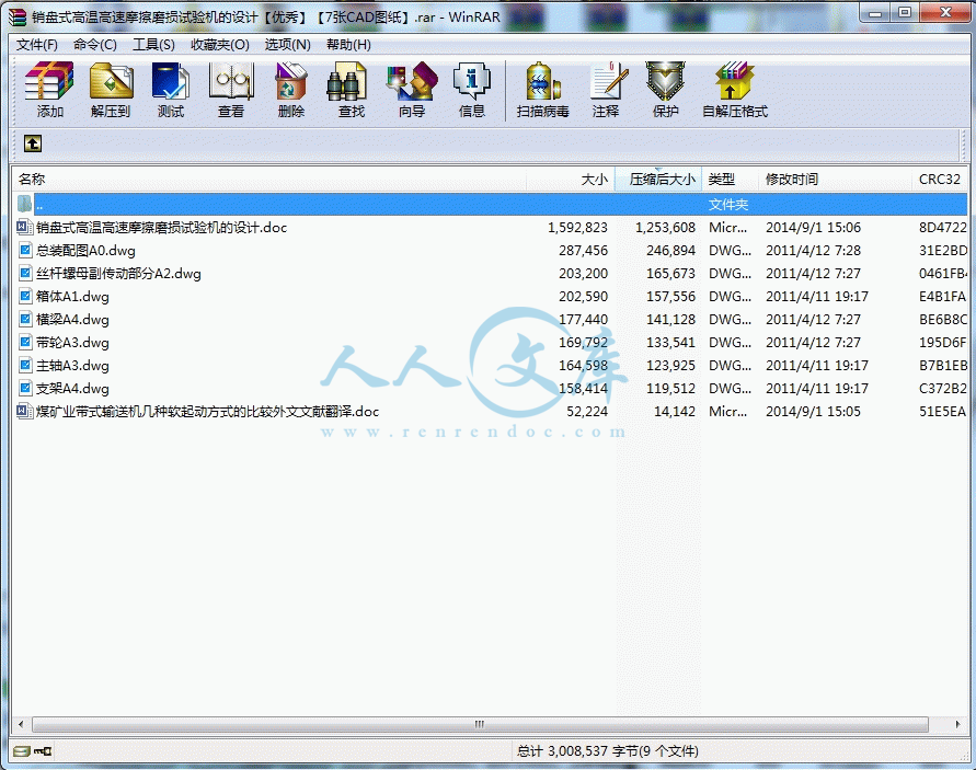
【word文档包含:外文翻译,43页@正文17000字】【详情如下】【需要咨询购买全套设计请加QQ1459919609】.bat

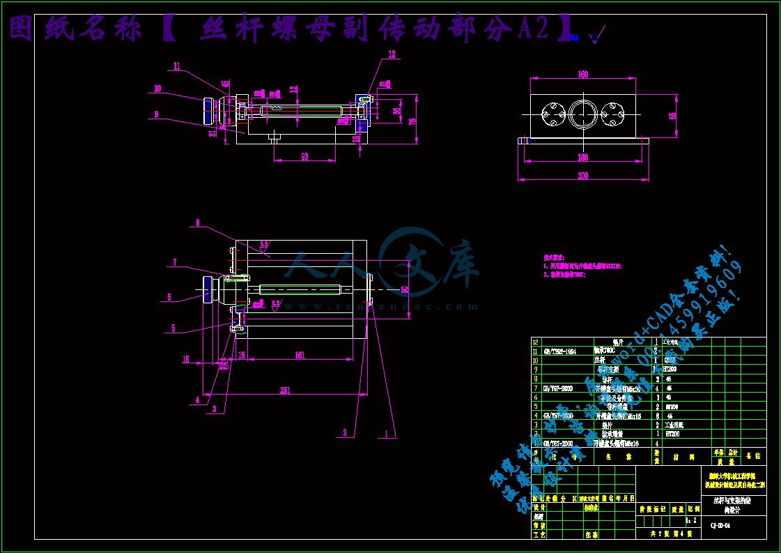
丝杆螺母副传动部分A2.dwg

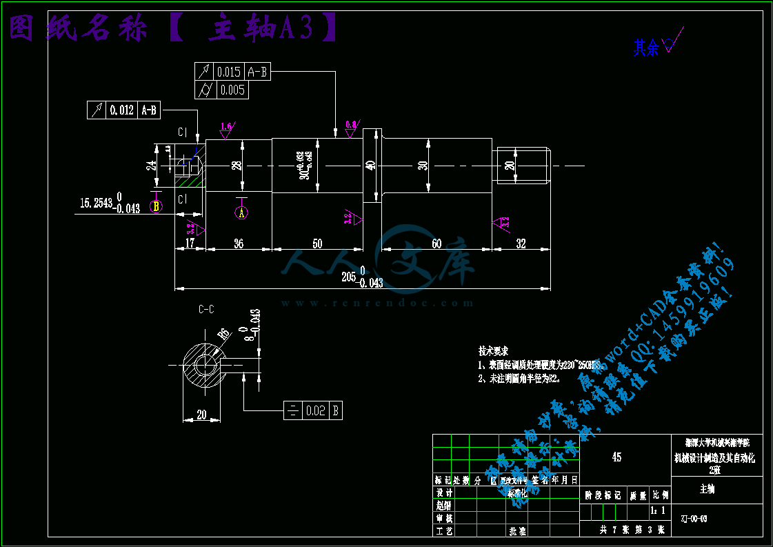
主轴A3.dwg

带轮A3.dwg

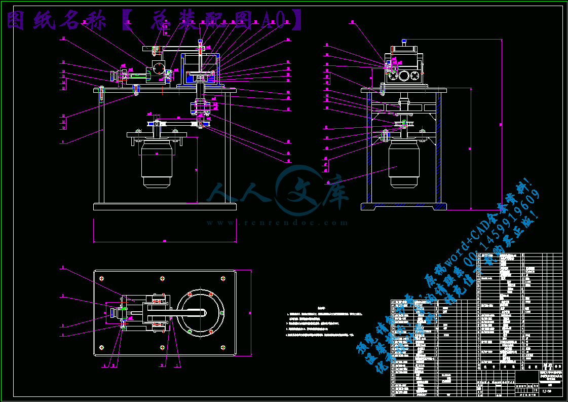
总装配图A0.dwg

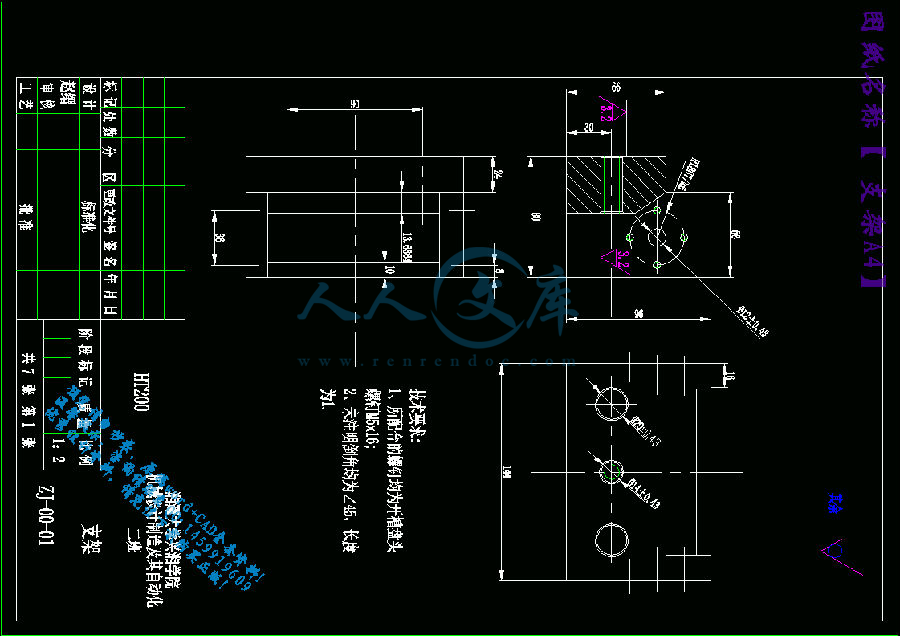
支架A4.dwg

横梁A4.dwg

煤矿业带式输送机几种软起动方式的比较外文文献翻译.doc

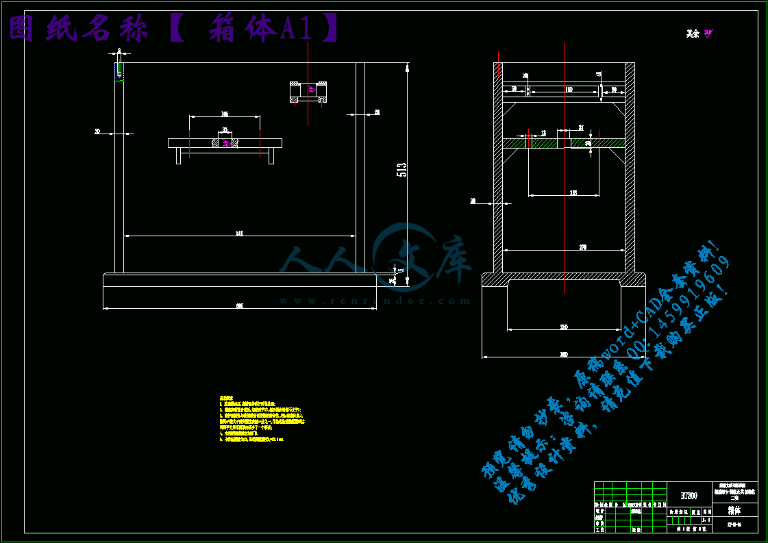
箱体A1.dwg

销盘式高温高速摩擦磨损试验机的设计.doc

目录

第一章 绪论2

1.1本课题研究的目的和意义2

1.2国内外研究概况3

1.3  发展趋势9

1.4  小结9

第二章  摩擦磨损试验机的影响因素10

2.1试验条件的影响;10

2.2、试验负荷的影响;13

第三章 方案设计、分析与比较16

3.1  试验机的整体分析16

3.2  设计方案的制定16

3.3  方案比较20

第四章 摩擦磨损试验机结构设计的相关计算22

4.1、试验机的主要性能指标的确定22

4.2试验机的主传动系统的相关计算22

4.2.1电机选择:22

4.2.2同步带传动的计算:24

4.2.3主轴计算:28

4.2.4、主轴上键的强度校核:30

4.2.5、横梁的强度校核:30

4.2.6、丝杠螺母副的相关计算:30

4.2.7、轴承的校核:31

第五章  摩擦磨损试验机的结构设计34

5.1、磨损试验机的整体结构34

5.2、箱体的结构设计35

5.3、横梁的设计35

5.4、支架的设计:36

5.5、摩擦销的结构设计:37

5.6、摩擦盘夹持器的设计:37

第六章 结 论38

致谢39

参考文献40

附录:外文翻译41

高温高速摩擦试验机

摘要:摩擦学是一门实践性很强的应用科学,在国内的相关研究中广泛使用的试验机有滚子式磨损试验机、四球式摩擦磨损试验机、往复式摩擦磨损试验机、切人式摩擦、磨损试验机、盘销式摩擦磨损试验机等。摩擦磨损试验的目的是为了对摩擦磨损现象及其本质进行研究,正确地评价各种因素对摩擦磨损性能的影响,从而确定符合使用要求的摩擦副元件的最优参数。高温高速摩擦磨损试验机是进行高温高速摩擦磨损试验的有效设备,广泛运用于对各种高速刀具的高温摩擦磨损性能进行测试和评价,是高速切削和新型刀具材料研制开发和应用的必备设备。该设备是高速加工和刀具材料研究方向研究工作急需的基础设备,该设备可以扩展该学科的研究领域和提高研究水平。

关键词:摩擦、试验机、高温、高速

High-temperature high-speed friction tester

Abstract: Friction is a very practical application of scientific research in China is widely used in a roller-type testing machine abrasion tester, four-ball friction and wear tester, reciprocating friction and wear test machine, cutting people friction and wear test machine, disc pins and other friction and wear test machine. The purpose of friction and wear tests on the friction and wear in order to study the phenomenon and its essence, the correct assessment of the various factors on the friction and wear properties to determine compliance requirements of the friction pair components using the optimal parameters. High temperature friction and wear tester is heat-efficient high-speed friction and wear test equipment, widely used in various high temperature friction and wear properties of tool to test and evaluation, and new high-speed cutting tool material developed and applied the necessary equipment . The device is a high-speed machining and cutting tool material research studies needed infrastructure, the device can be extended to the subject of basic research and research level.

Key words: friction testing machine, high temperature, high-speed

第一章 绪论

1.1本课题研究的目的和意义

摩擦学是一门实践性很强的应用科学,研究材料摩擦磨损行为一般需要借助摩擦磨损试验机测量摩擦副的摩擦磨损特性等一系列参量。在国内的相关研究中广泛使用的试验机有滚子式磨损试验机、四球式摩擦磨损试验机、往复式摩擦磨损试验机、切人式摩擦、磨损试验机、盘销式摩擦磨损试验机等。

随着冶金、矿山、电力以及工程机械等行业的发展,人们对磨损危害的认识有了相当的提高。为了弄清磨损机理以减少有害的磨损,各国学者对材料在常温下的各种磨损问题均进行了大量的研究,但对于材料在高温下的磨损问题至今却研究的较少,这和高温磨损试验装置的缺乏不无关系。1910年第一台磨料磨损试验机即以问世,1975年美国润滑工程师学会(ALSE)编著的“摩擦磨损装置”一书中所公布的不同类型的摩擦磨损试验机也有上百种,但其中大部分都是常温磨损试验机[1]。近几十年来,磨损试验机和试验方法虽然有了较大的发展,但这些试验机大多还是由企业和研究工作者根据工作需要和实际工况自行设计制造的,如高温磨料磨损试验机,适合高分子及其复合材料试验用的高温摩擦磨损试验机等。只有少数试验机是由专门的试验机厂或仪器制造公司制造和供应的,而且这些试验机大都结构复杂,价格较贵,这说明了磨损问题的复杂性和进行实验室磨损试验研究的困难所在。

摩擦磨损问题存在于人类物质活动的各个方面。在汽车、发电、设备、冶金、铁道、宇航、电子和农机等各方面的机械都大量存在着摩擦学的问题。据估计,全世界约有1/2- 1/3的能源以各种形式消耗在摩擦上,如果从摩擦学方面采取正确的措施,就可以大大节约能源消耗。磨损是机械零部件3种主要的失效形式之一,所导致的经济损失是巨大的,大约有80%的机械零件由于各种磨损导致失效。特别是随着物质文明的进步和工业技术现代化的发展,机械设备的开发使用普遍趋于重载、高速、高效率化,如何控制和改善机械的摩擦磨损状况、提高其使用寿命和工作可靠性,已成为机械工业技术人员必须关注的问题,并促使其研究不断的深入和发展。

这些摩擦试验机多采用静态选位法观察摩擦试件,虽然简单易行,但不能获得摩擦过程的动态信息,更不能对磨损(摩擦)过程进行动态观测及动态数据记录;另外由于受到试验机转速的限制,摩擦副相对运动的速度大多较低(一般不超过10m/s )。然而现代机械装备中许多摩擦副的相对滑动速度相当高,如高速 列车运行时的速度约为300km/h,制动时制动盘与刹车片之间摩擦速度为60~70m/s.而目前还未曾见到可用于高速条件下数据动态测量所需的商用摩擦磨损试验机。

摩擦磨损试验的目的是为了对摩擦磨损现象及其本质进行研究,正确地评价各种因素对摩擦磨损性能的影响,从而确定符合使用要求的摩擦副元件的最优参数。摩擦磨损试验研究的内容非常广泛,如探讨摩擦、磨损和润滑机理以及影响摩擦、磨损的诸因素,对新的耐磨、减磨及摩擦材料和润滑剂进行评定等。由于摩擦磨损现象十分复杂,摩擦磨损条件不同,试验方法和装置种类繁多,如何准确地获取摩擦磨损过程中的参数变化成为一个十分重要的研究课题。为了探索和验证机械工程中摩擦磨损问题的机理以及有关影响因素,在摩擦学研究中开展摩擦磨损测试技术和数据分析研究具有非常重要的作用。

高温高速摩擦磨损试验机是进行高温高速摩擦磨损试验的有效设备,广泛运用于对各种高速刀具的高温摩擦磨损性能进行测试和评价,是高速切削和新型刀具材料研制开发和应用的必备设备。该设备是高速加工和刀具材料研究方向研究工作急需的基础设备,该设备可以扩展该学科的研究领域和提高研究水平。

1.2国内外研究概况

摩擦试验机对冶金、矿山、电力以及工程机械等行业的发展有着至关重要的作用,随着目前世界各国科技的飞速发展,各个行业在技术上的突飞猛进摩擦试验机对于各行业的重要性也越来越明显.

目前,世界只有美国、日本、瑞士等少数几个国家有摩擦磨损试验机的专业生产企业,而济南试金集团是国内最早研制和生产摩擦磨损试验机的厂家。早在1964年为了满足我国石油工业和材料工业的发展需要,济南试金集团开始研制MQ-12型四球摩擦试验机,1965年研制成功并投入生产,1966年又研制成功MM-200型磨损试验机,两种试验机的研制成功标志着我国已有了自行研制摩擦磨损试验机的能力。在最近的几年,涌现出了一批新兴生产摩擦磨损试验机的企业,也有不少优质产品面世。

济南竟成测试技术有限公司生产的SFT-2M销盘式摩擦磨损试验机:

仪器工作原理:本试验装置适用于材料表面和材料涂层的摩擦磨损测试。可提供较宽的负载范围和旋转速度。可进行球-盘、栓(销)-盘、盘-盘的不同摩擦副的试验,精确测量在不同摩擦方式下,材料的摩擦系数、磨痕深度及耐磨性,操作简便,测量精度高。

参考文献

[1]武文忠,郝建东,苏俊义.高温磨损试验机的研制.北京:试验技术与试验机,2002,42(1,2),15~17

[2]桂长林,沈健.摩擦磨损试验机设计的基础:Ⅰ[1].摩擦磨损试验机的分类和特点分析。合肥:固体润滑.1990,10(1),48~55

[3]桂长林,沈健.摩擦磨损试验机设计的基础:II摩擦磨损试验机设计方法的研究。合肥:固体润滑。1990,10(2),120~136

[4]杨学军,赵浩峰,赵昕月.高温销盘磨损试验机的研制.太原:太原理工大学学报,2005,36(4),477~479

[5]李霞,许志庆,杨永.高速摩擦磨损试验机的总体设计.北京:中国仪器仪表,2003,19~21

[6]桑可正,金志浩。MPX—2000型盘销式摩擦磨损试验机的改装.北京:机械科学与技术。1999.18(3),470~471,474

[7]何国仁,曾汉民,杨桂成.高温摩擦磨损试验机的研制.北京:北京:试验技术与试验机.1991,31(5),11~16

[8]王斌,蔡兴旺.一种摩擦磨损试验机的设计.北京:农机化研究。2003,10,118~119

[9]冯辛安.机械制造装备设计.北京:机械工业出版社。2004年1月

[10]成大先.机械设计手册(单行本)机械传动.北京:化学工业出版社.2004年1月

[11]成大先.机械设计手册(单行本)机械工程材料.北京:化学工业出版社。2004年1月

[12]成大先.机械设计手册(单行本) 减(变)速器&电机与电气.北京:化学工业出版社.2004年1月

[13]成大先.机械设计手册(单行本)连接与紧固.北京:化学工业出版社。2004年1月

[14]濮良贵、纪名刚.机械设计.北京:高等教育出版社.2007年8月

[15]李凯岭,宋强.机械制造技术基础.济南:山东科技出版社.2005年9月

[16]焦永和,董国耀.机械制图.北京:北京理工大学出版社.2001年7月

[17]周良德、朱泗芳.现代工程图学.湖南:湖南科学技术出版社.2000年6月

[18]罗迎社,材料力学.武汉:武汉理工大学出版社.2004年6月


内容简介:
附录:外文翻译煤矿业带式输送机几种软起动方式的比较el L. Nave, P.E.统一公司1800 年华盛顿路匹兹堡, PA 15241带式运送机是采矿工业运输大批原料的重要方法。从传送带驱动系统到传送带纹理结构启动力矩的应用和控制影响着运送机的性能,寿命和可靠性。本文考查了不同启动方法在煤矿工业带式运送机中的应用。简介运行带式运送机的动力必须由驱动滑轮产生,通过滑轮和传送带之间的摩擦力来传递。为了传递能量,传送带上面的张力在接近滑轮部分和离开滑轮部分必定存在着差别。这种差别在稳定运行、启动和停止时刻都是真实存在的。传统传送带结构的设计,都是根据稳定运行情况下传送带的受力情况。因为设计过程中没有详尽研究传送带启动和停止阶段的受力情况,所有的安全措施都集中在稳定运行阶段(Harrison 1987)。本文主要集中讲述传送机启动和加速阶段的特性。传送带设计者在设计时必须考虑控制启动阶段的加速状况,以免使传送带和传送机驱动系统产生过大的张力和动力(Suttees,1986)。大加速度产生的动力会给传送带的纹理、传送带结合处、驱动滑轮、轴承、减速器以及耦合器带来负面影响。毫无控制的加速度产生的动力能够引起带式传送机系统产生诸多不良问题,比如上下曲线运动、过度传送带提升运动、滑轮和传送带打滑、运输原料的溢出和传送带结构。传送带的设计需要面对两个问题:第一,传送带驱动系统必须能够产生启动带式传送机的最小转动力矩;第二,控制加速度产生动力在安全界限内。可以通过驱动力矩控制设备来完成,控制设备可以是电子手段也可以是机械手段,也可以是两者的组合(CEM,1979)。本文主要阐述输送机的开始和加速的过程。传送带设计师必须控制开始加速度防止过度张紧在传送带织品和力量在皮带传动系统. 强加速度力量可能有害地影响传送带织品,传送带接合,驱动皮带轮,更加无所事事的滑轮, 轴, 轴承, 速度还原剂, 并且联结。未管制的加速度力量可能造成皮带输送机有垂直的曲线的系统性能问题,传送带紧线器运动, 驱动皮带轮摩擦损失, 材料溢出, 并且做成花彩传送带织品。传送带设计员与二个问题被面对, 皮带传动系统必须导致极小的扭矩足够强有力开始传动机, 和控制了这样加速度强制是在安全限额内。光滑开始传动机可能由对驱动器扭矩控制设备的用途, 或机械或电子, 或组合的二完成(CEM 1979) 。软起动结构评估标准什么是最佳的皮带输送机驱动系统? 答案取决于许多变量。最佳的系统是一个为开始, 运行, 和终止提供可接受的控制在合理的费用和以及高可靠性。皮带传动系统为本文我们考虑的设计方案, 皮带输送机被电子头等搬家工人几乎总驱动。传送带驱动系统 将包括多个要素包括电子原动力、电子马达起始者以控制系统, 马达联结、速度还原剂、低速联结、皮带传动滑轮、和滑轮闸 (Cur 1986) 。它重要, 传送带设计员审查各个系统要素的适用性对特殊申请。为本文的目的, 我们假设, 所有驱动系统要素设置矿的新鲜空气, 非允许, 面积,全国电子编码, 条款500 防爆, 矿的表面的面积。皮带传动要素归因于范围。某些驱动器要素是可利用和实用的用不同的范围。为这论述, 我们假设那皮带传动系统范围从分数马力对千位的多个马力。小驱动系统经常是在50 马力以下。中型系统范围从50 到1000 马力。大型系统可能被考虑在1000 马力之上。范围分部入这些组是整个地任意的。必须被保重抵抗诱惑对超出马达或在马达之下传送带飞行提高标准化。驱动器结果在粗劣的效率和在高扭矩的潜在, 当驱动器能导致破坏性超速在再生, 或过度加热以变短的马达寿命。扭矩控制。传送带设计员设法限制开始的扭矩到没有比150% 运行中。限额在应用的开始的扭矩经常是传送带胴体肉、传送带接合、滑轮绝热材料,轴偏折评级。在更大的传送带和传送带以优化大小的要素, 扭矩限额110% 至125% 是公用。除扭矩限额之外, 传送带起始者必需限制会舒展围绕和会导致旅行的波浪的扭矩增量。一个理想的开始的控制系统会适用于资格整个传送带的扭矩传送带休息由问题的脱离决定, 或运动, 然后扭矩相等与传送带的运动需求以负荷加上恒定的扭矩从休息加速系统要素的惯性对最终奔跑速度。这使系统临时强制和传送带舒展。不同的驱动系统陈列变化的能力控制扭矩的申请对传送带休息和以不同的速度。并且, 传动机陈列装载二个极端。一条空传送带正常存在最小的必需的扭矩为脱离和加速度, 当一条充分地被装载的传送带存在最高的必需的扭矩。开采驱动系统必须是能称应用的扭矩从一个2/1 比率为一个水平的简单传送带安排, 对一个10/1 范围为一个倾斜、复杂传送带配置文件。 热量评级在开始和运行期间, 各个驱动系统也许消散废热。废热也许被解放在电子马达、电子控制、, 联结、速度还原剂, 或传送带制动系统。各个起始时间热量负荷依靠相当数量传送带负荷和起始时间的期限。设计员必须履行被重复的起始时间的申请需求在运行传动机以后在全负荷。典型的开采传送带开始的责任变化从3到10 个起始时间每时数等隔,或2到4 个起始时间在连续。被重复的开始也许要求减税或系统要素。有一个直接关系在热量评级为被重复的起始时间和费用之间。可变速度。一些皮带传动系统是适当的为控制开始的扭矩和速度, 但只运行以恒定的速度。一些传送带申请会要求一个驱动系统能运行延长的期间以较不比最高速度。这是有用的当驱动器负荷必须与其它驱动器被共享,传送带被使用当处理饲养者为被表达的物料的费率控制, 传送带速度被优选为货车使用费费率,传送带被使用以慢速运输人工或材料, 或传送带运行缓慢的检验或移动速度为维护目的。可变速度皮带传动将要求一个控制系统根据某一算法调控操作速度。再生或翻修负荷。一些传送带配置文件存在翻修传送带系统用品能量对驱动系统的负荷的潜在。没有所有驱动系统有能力接受被重新生成的能量从负荷。一些驱动器可能接受能量从负荷和退回它到输电线供其它负荷使用。其它驱动器接受能量从负荷和消散它入选定的动态或机械刹车的要素。一些传送带描出切换从开汽车对再生在运算期间。驱动系统可能接受有些巨大的被重新生成的能量为申请吗? 驱动系统控制或必须调整相当数量减速的强制在翻修期间吗?翻修发生当运行和开始? 维护和支持系统。各个驱动系统将要求定期预防维护。可替换的项目会包括马达画笔、轴承、闸填充、散逸电阻器、油, 和凉水。如果驱动系统被设计和保守地被管理, 更低的重音在可消耗导致更低的维修费用。一些驱动器要求支持系统譬如流通的油为润滑油、冷却空气或水, 环境尘土过滤, 或计算机仪器工作。支持系统的维护可能影响驱动系统的可靠性。费用驱动器设计员将审查各个驱动系统的费用。费用合计是第一基建成本获取驱动器, 费用安装和委任驱动器, 费用运行驱动器, 和费用的总和维护驱动器。费用使力量运行驱动器也许广泛变化用不同的地点。设计员努力符合所有系统性能要求在最低的费用合计。经常超过一个驱动系统也许满足所有系统性能标准在竞争费用。更喜欢的驱动器安排是最简单, 譬如一个唯一马达驱动通过一个唯一顶头滑轮。但是, 机械, 经济, 和功能需求经常需要对复杂驱动器的用途。传送带设计员必须平衡对优雅的需要反对伴随复杂系统的问题。复杂系统要求额外设计工程为成功配置。经常被忽略的费用在复杂系统是培训人事部的费用, 或停工期的费用由于不足的培训。软起动驱动控制逻辑各个驱动系统将要求一个控制系统调控开始的机制。最共同的类型控制被使用在更小对中等大小驱动以简单的外形被命名开环加速度控制 。 在开环, 控制系统早先被配置程序化开始的机制以被规定的方式, 通常准时根据。 在开环控制, 驾驶使用参数譬如潮流, 扭矩, 或速度不影响序列操作。 这个方法假定, 控制设计师充分地塑造了驱动系统表现在传动机。 为更大或更加复杂的传送带, 闭合回路 或反馈 控制可以他运用了。 在闭合回路控制, 在开始期间, 控制系统显示器通过传感器驾驶使用参数譬如马达的当前层, 传送带的速度, 或力量在传送带, 并且修改起动程序控制, 极限, 或优选或佩带了参量。闭合回路控制系统修改开始的被应用的力量在一台空和充分地被装载的传动机之间。常数在数学模型与被测量的可变物有关对系统驱动反应被命名定调的常数。 这些常数必须适当地被调整为成功的应用对各台传动机。 最共同的计划为传动机开始闭合回路控制是车头表反馈为速度控制和压电池力量或驱动力反馈为扭矩控制。在一些复杂系统, 它是中意安排闭合回路控制系统调整自己为各种各样的遇到的传动机情况。 这被命名能适应的控制 。这些极端可能介入浩大的变异在装货, 围绕的温度, 装货的地点在外形, 或多个驱动选择在传动机。 有三个共同的能适应的方法。介入决定做在开始之前,如果控制系统能知道传送带是空的, 它会减少最初的力量和会加长加速度力量的应用对最高速度。如果传送带被装载, 控制系统会应用资格力量在摊位之下使较少时刻和供应充足的扭矩及时地充分地加速传送带。 因为传送带只成为了装载在早先赛跑期间由装载驱动, 平均驱动潮流可能被抽样当连续和被保留在反射传送带搬运器时间的缓冲记忆。然后在停工平均也许是预先处理一些开环和闭合回路为下个开始。第二个方法介入根据驱动观察发生在最初开始或行动期间证明 的决定。这及时驱动潮流的或力量通常介入比较对传送带速度。 如果驱动潮流或力量必需及早在序列是降低并且行动被创始, 传送带必须被卸载。如果驱动潮流或力量必需是高的。在开始, 传动机必须被装载。 这个决定可能被划分在区域和使用修改起动程序控制的中部和结束。第三个方法介入传送带速度的比较对时刻为这个开始反对传送带加速度历史极限, 或 加速度信封监视。在开始, 传送带速度被测量对时间。这与被保留在控制系统记忆的二限制的传送带速度曲线比较。第一曲线描出空的传送带加速, 并且第二个充分地被装载的传送带。 因而, 如果当前的速度对时间比被装载的外形低, 它也许表明, 传送带被超载, 妨碍, 或驱动故障。 如果当前的速度对时间比空间的外形高级, 它也许表明一条残破的传送带结合或驱动故障。 无论如何,当前的起飞中止并且警报运行。结论最好的传送带启动系统要求在不同的传送带负载条件下,能够以合理的代价带来可靠性高的可以接受的运行性能。但是至今没有一个启动系统能够达到这样的要求。传送带设计者必须为每个传送带设计启动系统属性。总得来说,全电压交流发动机启动适合于简单结构的小型传送带。减电压SCR交流发动机启动是地下中、小型传送带的基本启动方法。最新的进展显示,固定液体填充耦合系统的交流发动机是简单结构中、大型传送带基本启动方法。对于那些大、中型而且需要重复启动的复杂结构传送带,绕线转子发动机驱动是常用的选择。在结构特别复杂,运行需要不同速度的传送带启动中,传送带直流发动机驱动、不同填充液体驱动、和相异机械传递驱动系统一直实力相当的候选者。具体选择哪个启动方式由使用环境,相对价格,运行能耗,反应速度和使用者习惯来决定。变频交流驱动和非电刷直流驱动主要限制于中型传送带,这些中型传送带需要精确的速度控制,高代价和复杂性。但是,随着持续的竞争和技术进步,波形综合技术的电子驱动器的使用将越来越广。A Comparison of Soft Start Mechanisms for Mining Belt ConveyorsMichael L. Nave, P.E.CONSOL Inc.1800 Washington Road Pittsburgh, PA 15241 Belt Conveyors are an important method for transportation of bulk materials in the mining industry. The control of the application of the starting torque from the belt drive system to the belt fabric affects the performance, life cost, and reliability of the conveyor. This paper examines applications of each starting method within the coal mining industry.INTRODUCTIONThe force required to move a belt conveyor must be transmitted by the drive pulley via friction between the drive pulley and the belt fabric. In order to transmit power there must be a difference in the belt tension as it approaches and leaves the drive pulley. These conditions are true for steady state running, starting, and stopping. Traditionally, belt designs are based on static calculations of running forces. Since starting and stopping are not examined in detail, safety factors are applied to static loadings (Harrison, 1987). This paper will primarily address the starting or acceleration duty of the conveyor. The belt designer must control starting acceleration to prevent excessive tension in the belt fabric and forces in the belt drive system (Suttees, 1986). High acceleration forces can adversely affect the belt fabric, belt splices, drive pulleys, idler pulleys, shafts, bearings, speed reducers, and couplings. Uncontrolled acceleration forces can cause belt conveyor system performance problems with vertical curves, excessive belt take-up movement, loss of drive pulley friction, spillage of materials, and festooning of the belt fabric. The belt designer is confronted with two problems, The belt drive system must produce a minimum torque powerful enough to start the conveyor, and controlled such that the acceleration forces are within safe limits. Smooth starting of the conveyor can be accomplished by the use of drive torque control equipment, either mechanical or electrical, or a combination of the two (CEM, 1979).SOFT START MECHANISM EVALUATION CRITERIONWhat is the best belt conveyor drive system? The answer depends on many variables. The best system is one that provides acceptable control for starting, running, and stopping at a reasonable cost and with high reliability (Lewdly and Sugarcane, 1978). Belt Drive System For the purposes of this paper we will assume that belt conveyors are almost always driven by electrical prime movers (Goodyear Tire and Rubber, 1982). The belt drive system shall consist of multiple components including the electrical prime mover, the electrical motor starter with control system, the motor coupling, the speed reducer, the low speed coupling, the belt drive pulley, and the pulley brake or hold back (Cur, 1986). It is important that the belt designer examine the applicability of each system component to the particular application. For the purpose of this paper, we will assume that all drive system components are located in the fresh air, non-permissible, areas of the mine, or in non-hazardous, National Electrical Code, Article 500 explosion-proof, areas of the surface of the mine. Belt Drive Component Attributes Size.Certain drive components are available and practical in different size ranges. For this discussion, we will assume that belt drive systems range from fractional horsepower to multiples of thousands of horsepower. Small drive systems are often below 50 horsepower. Medium systems range from 50 to 1000 horsepower. Large systems can be considered above 1000 horsepower. Division of sizes into these groups is entirely arbitrary. Care must be taken to resist the temptation to over motor or under motor a belt flight to enhance standardization. An over motored drive results in poor efficiency and the potential for high torques, while an under motored drive could result in destructive overspending on regeneration, or overheating with shortened motor life (Lords, et al., 1978).Torque Control. Belt designers try to limit the starting torque to no more than 150% of the running torque (CEMA, 1979; Goodyear, 1982). The limit on the applied starting torque is often the limit of rating of the belt carcass, belt splice, pulley lagging, or shaft deflections. On larger belts and belts with optimized sized components, torque limits of 110% through 125% are common (Elberton, 1986). In addition to a torque limit, the belt starter may be required to limit torque increments that would stretch belting and cause traveling waves. An ideal starting control system would apply a pretension torque to the belt at rest up to the point of breakaway, or movement of the entire belt, then a torque equal to the movement requirements of the belt with load plus a constant torque to accelerate the inertia of the system components from rest to final running speed. This would minimize system transient forces and belt stretch (Shultz, 1992). Different drive systems exhibit varying ability to control the application of torques to the belt at rest and at different speeds. Also, the conveyor itself exhibits two extremes of loading. An empty belt normally presents the smallest required torque for breakaway and acceleration, while a fully loaded belt presents the highest required torque. A mining drive system must be capable of scaling the applied torque from a 2/1 ratio for a horizontal simple belt arrangement, to a 10/1 ranges for an inclined or complex belt profile.Thermal Rating. During starting and running, each drive system may dissipate waste heat. The waste heat may be liberated in the electrical motor, the electrical controls, the couplings, the speed reducer, or the belt braking system. The thermal load of each start Is dependent on the amount of belt load and the duration of the start. The designer must fulfill the application requirements for repeated starts after running the conveyor at full load. Typical mining belt starting duties vary from 3 to 10 starts per hour equally spaced, or 2 to 4 starts in succession. Repeated starting may require the dreading or over sizing of system components. There is a direct relationship between thermal rating for repeated starts and costs. Variable Speed. Some belt drive systems are suitable for controlling the starting torque and speed, but only run at constant speed. Some belt applications would require a drive system capable of running for extended periods at less than full speed. This is useful when the drive load must be shared with other drives, the belt is used as a process feeder for rate control of the conveyed material, the belt speed is optimized for the haulage rate, the belt is used at slower speeds to transport men or materials, or the belt is run a slow inspection or inching speed for maintenance purposes (Hager, 1991). The variable speed belt drive will require a control system based on some algorithm to regulate operating speed. Regeneration or Overhauling Load. Some belt profiles present the potential for overhauling loads where the belt system supplies energy to the drive system. Not all drive systems have the ability to accept regenerated energy from the load. Some drives can accept energy from the load and return it to the power line for use by other loads. Other drives accept energy from the load and dissipate it into designated dynamic or mechanical braking elements. Some belt profiles switch from motoring to regeneration during operation. Can the drive system accept regenerated energy of a certain magnitude for the application? Does the drive system have to control or modulate the amount of retarding force during overhauling? Does the overhauling occur when running and starting? Maintenance and Supporting Systems. Each drive system will require periodic preventative maintenance. Replaceable items would include motor brushes, bearings, brake pads, dissipation resistors, oils, and cooling water. If the drive system is conservatively engineered and operated, the lower stress on consumables will result in lower maintenance costs. Some drives require supporting systems such as circulating oil for lubrication, cooling air or water, environmental dust filtering, or computer instrumentation. The maintenance of the supporting systems can affect the reliability of the drive system. Cost. The drive designer will examine the cost of each drive system. The total cost is the sum of the first capital cost to acquire the drive, the cost to install and commission the drive, the cost to operate the drive, and the cost to maintain the drive. The cost for power to operate the drive may vary widely with different locations. The designer strives to meet all system performance requirements at lowest total cost. Often more than one drive system may satisfy all system performance criterions at competitive costs.Complexity. The preferred drive arrangement is the simplest, such as a single motor driving through a single head pulley. However, mechanical, economic, and functional requirements often necessitate the use of complex drives. The belt designer must balance the need for sophistication against the problems that accompany complex systems. Complex systems require additional design engineering for successful deployment. An often-overlooked cost in a complex system is the cost of training onsite personnel, or the cost of downtime as a result of insufficient training. SOFT START DRIVE CONTROL LOGICEach drive system will require a control system to regulate the starting mechanism. The most common type of control used on smaller to medium sized drives with simple profiles is termed Open Loop Acceleration Control. In open loop, the control system is previously configured to sequence the starting mechanism in a prescribed manner, usually based on time. In open loop control, drive-operating parameters such as current, torque, or speed do not influence sequence operation. This method presumes that the control designer has adequately modeled drive system performance on the conveyor. For larger or more complex belts, Closed Loop or Feedback control may he utilized. In closed loop control, during starting, the control system monitors via sensors drive operating parameters such as current level of the motor, speed of the belt, or force on the belt, and modifies the starting sequence to control, limit, or optimize one or wore parameters. Closed loop control systems modify the starting applied force between an empty and fully loaded conveyor. The constants in the mathematical model related to the measured variable versus the system drive response are termed the tuning constants. These constants must be properly adjusted for successful application to each conveyor. The most common schemes for closed loop control of conveyor starts are tachometer feedback for speed control and load cell force or drive force feedback for torque control. On some complex systems, It is desirable to have the closed loop control system adjust itself for various encountered conveyor conditions. This is termed Adaptive Control. These extremes can involve vast variations in loadings, temperature of the belting, location of the loading on the profile, or multiple drive options on the conveyor. There are three common adaptive methods. The first involves decisions made before the start, or Restart Conditioning. If the control system could know that the belt is empty, it would reduce initial force and lengthen the application of acceleration force to full speed. If the belt is loaded, the control system would apply pretension forces under stall for less time and supply sufficient torque to adequately accelerate the belt in a timely manner. Since the belt only became loaded during previous running by loading the drive, the average drive current can be sampled when running and retained in a first-in-first-out buffer memory that reflects the belt conveyance time. Then at shutdo wn the FIFO average may be use4 to precondition some open loop and closed loop set points for the next start. The second method involves decisions that are based on drive observations that occur during initial starting or Motion Proving. This usually involves a comparison In time of the drive current or force versus the belt speed. if the drive current or force required early in the sequence is low and motion is initiated, the belt must be unloaded. If the drive current or force required is high and motion is slow in starting, the conveyor must be loaded. This decision can be divided in zones and used to modify the middle and finish of the start sequence control. The third method involves a comparison of the belt speed versus time for this start against historical limits of belt acceleration, or Acceleration Envelope Monitoring. At start, the belt speed is measured versus time. This is compared with two limiting belt speed curves that are retained in control system memo
温馨提示:
1: 本站所有资源如无特殊说明,都需要本地电脑安装OFFICE2007和PDF阅读器。图纸软件为CAD,CAXA,PROE,UG,SolidWorks等.压缩文件请下载最新的WinRAR软件解压。
2: 本站的文档不包含任何第三方提供的附件图纸等,如果需要附件,请联系上传者。文件的所有权益归上传用户所有。
3.本站RAR压缩包中若带图纸,网页内容里面会有图纸预览,若没有图纸预览就没有图纸。
4. 未经权益所有人同意不得将文件中的内容挪作商业或盈利用途。
5. 人人文库网仅提供信息存储空间,仅对用户上传内容的表现方式做保护处理,对用户上传分享的文档内容本身不做任何修改或编辑,并不能对任何下载内容负责。
6. 下载文件中如有侵权或不适当内容,请与我们联系,我们立即纠正。
7. 本站不保证下载资源的准确性、安全性和完整性, 同时也不承担用户因使用这些下载资源对自己和他人造成任何形式的伤害或损失。
提示  人人文库网所有资源均是用户自行上传分享,仅供网友学习交流,未经上传用户书面授权,请勿作他用。
关于本文
本文标题:销盘式高温高速摩擦磨损试验机的设计【优秀】【7张CAD图纸】
链接地址:https://www.renrendoc.com/p-317764.html

官方联系方式

2:不支持迅雷下载,请使用浏览器下载   
3:不支持QQ浏览器下载,请用其他浏览器   
4:下载后的文档和图纸-无水印   
5:文档经过压缩,下载后原文更清晰   
关于我们 - 网站声明 - 网站地图 - 资源地图 - 友情链接 - 网站客服 - 联系我们

网站客服QQ:2881952447     

copyright@ 2020-2025  renrendoc.com 人人文库版权所有   联系电话:400-852-1180

备案号:蜀ICP备2022000484号-2       经营许可证: 川B2-20220663       公网安备川公网安备: 51019002004831号

本站为文档C2C交易模式,即用户上传的文档直接被用户下载,本站只是中间服务平台,本站所有文档下载所得的收益归上传人(含作者)所有。人人文库网仅提供信息存储空间,仅对用户上传内容的表现方式做保护处理,对上载内容本身不做任何修改或编辑。若文档所含内容侵犯了您的版权或隐私,请立即通知人人文库网,我们立即给予删除!