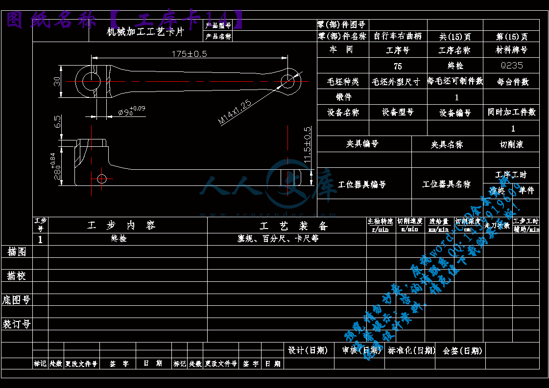
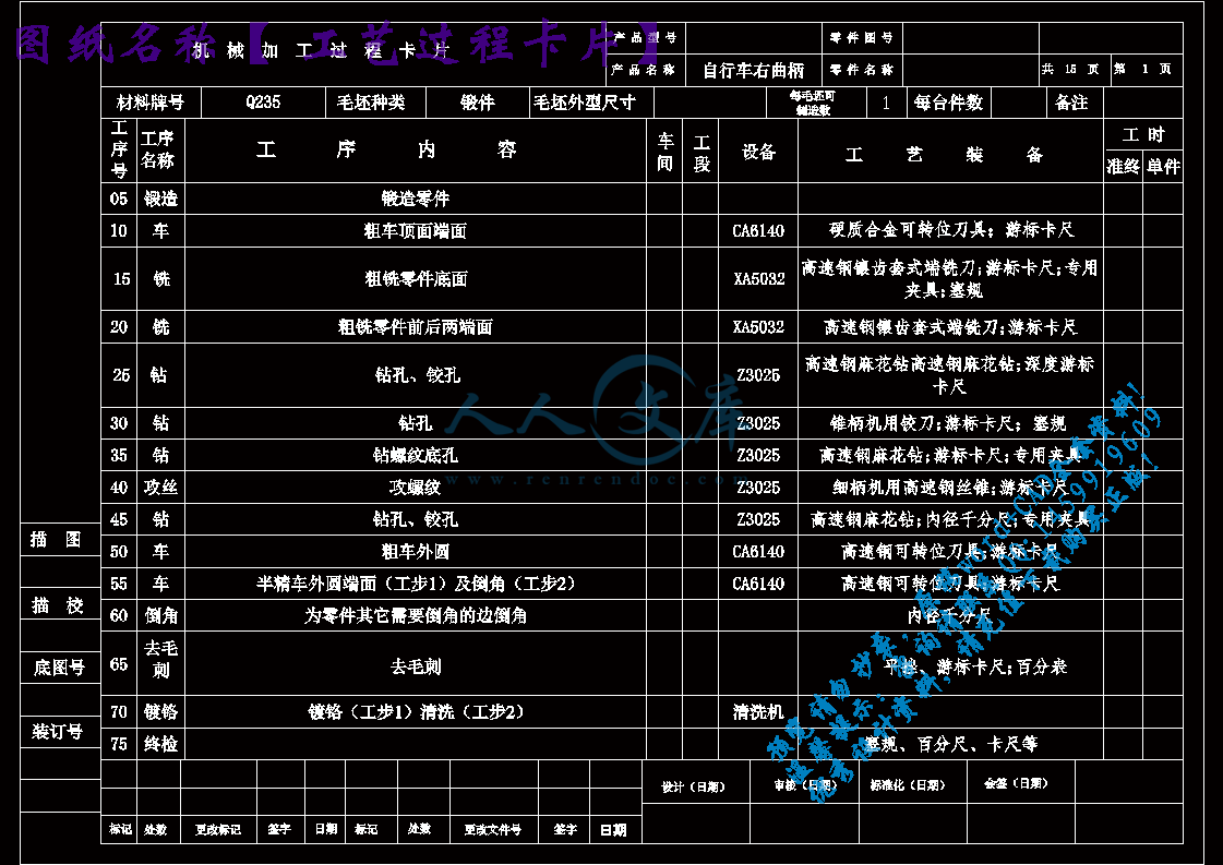
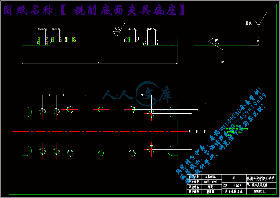
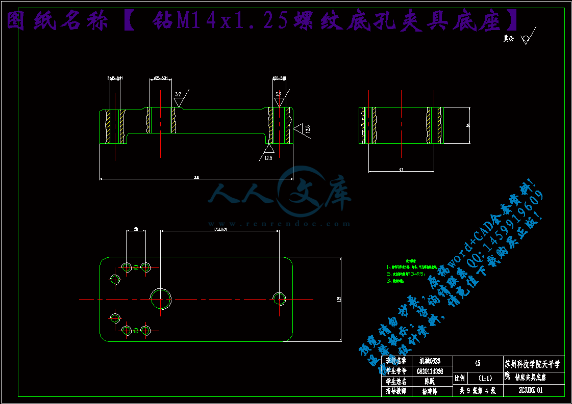
零件图副本.dwg
零件图副本.dwg

自行车右曲柄的加工工艺规程及夹具设计【铣底面】【钻M14x1.25螺纹底孔】【钻φ9孔】【优秀】【工艺装备3套夹具类】【9张CAD图纸全套】【ZXCYQB01】

收藏

资源目录
跳过导航链接。
压缩包内文档预览:
预览图
编号:328514    类型:共享资源    大小:1.69MB    格式:RAR    上传时间:2014-09-25 上传人:QQ14****9609 IP属地:陕西
120
积分
关 键 词:
自行车右曲柄 右曲柄 机械加工 加工工艺 工艺规程 夹具设计 工艺装备
资源描述:

自行车右曲柄工装设计

自行车右曲柄铣削底面工艺装备【夹具】设计

自行车右曲柄钻M14x1.25螺纹底孔工艺装备【夹具】设计

自行车右曲柄钻φ9孔工艺装备【夹具】设计

自行车右曲柄的加工工艺编制及夹具设计

自行车右曲柄的加工工艺规程及工艺装备【夹具】设计

自行车右曲柄的加工工艺规程及工装设计

自行车右曲柄的加工工艺规程及夹具设计【铣底面】【钻M14x1.25螺纹底孔】【钻φ9孔】【优秀】【工艺装备3套夹具类】【9张CAD图纸全套】【ZXCYQB01】

【带任务书+开题报告+外文翻译,工艺过程、工序卡片全套】【word文档包含:37页@正文12600字】【详情如下】【需要咨询购买全套设计请加QQ1459919609 】.bat

任务书.doc

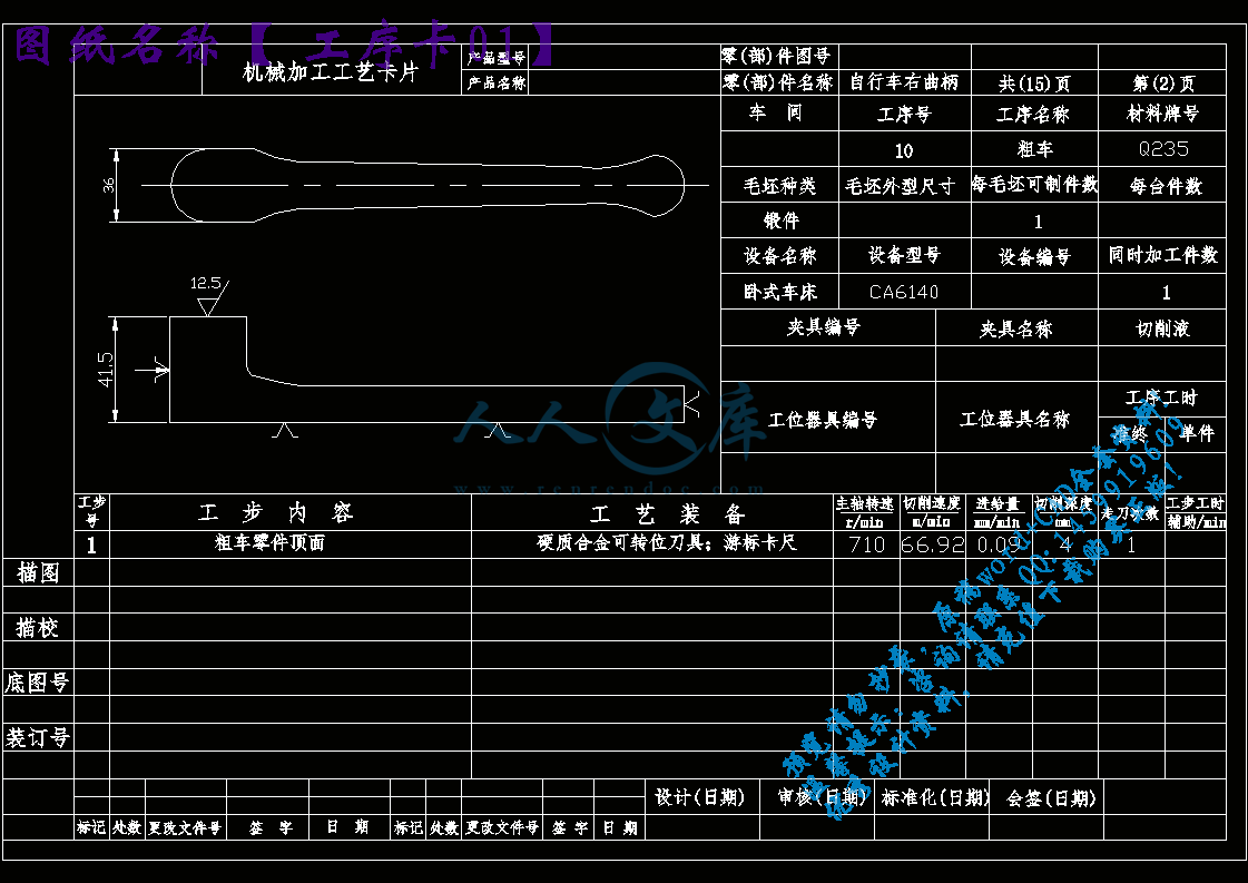
工序卡01.dwg

工序卡010.dwg

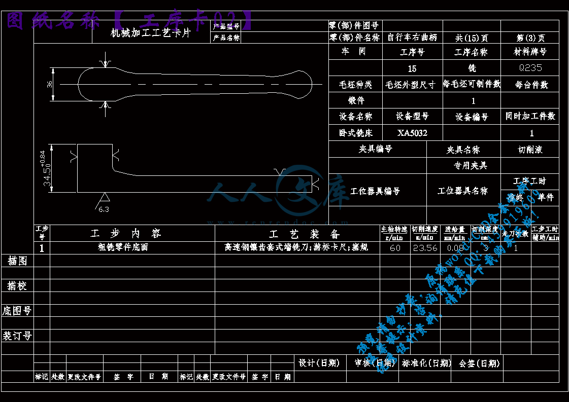
工序卡02.dwg

工序卡03.dwg

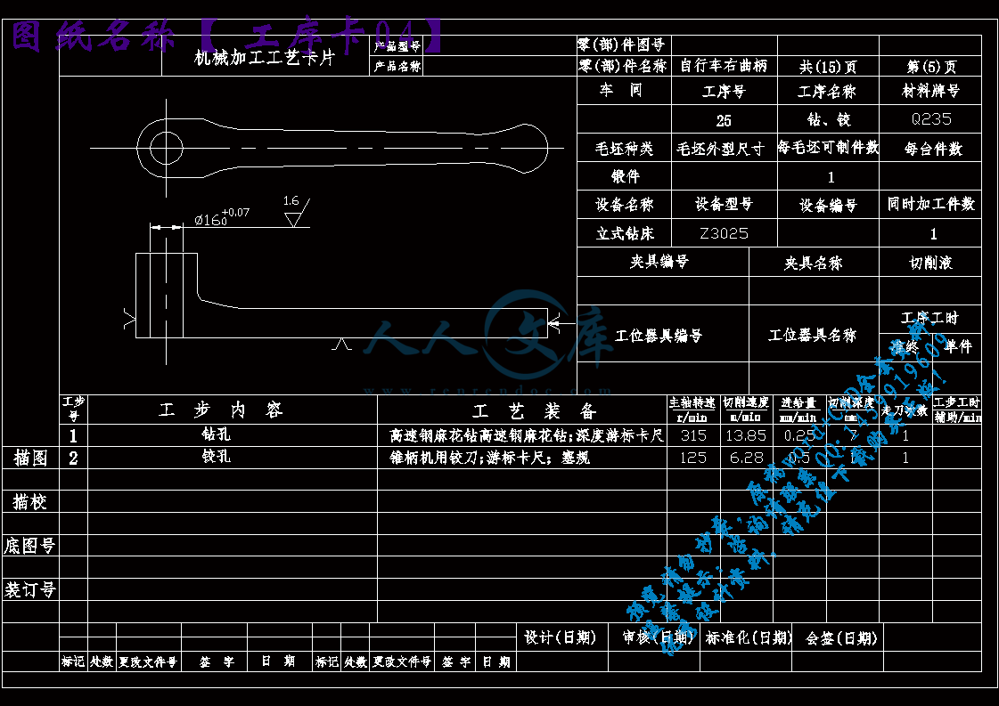
工序卡04.dwg

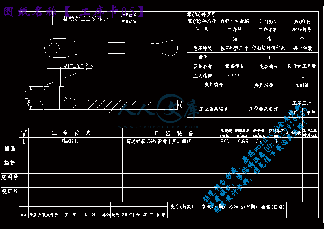
工序卡05.dwg

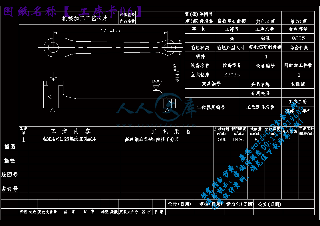
工序卡06.dwg

工序卡07.dwg

工序卡08.dwg

工序卡09.dwg

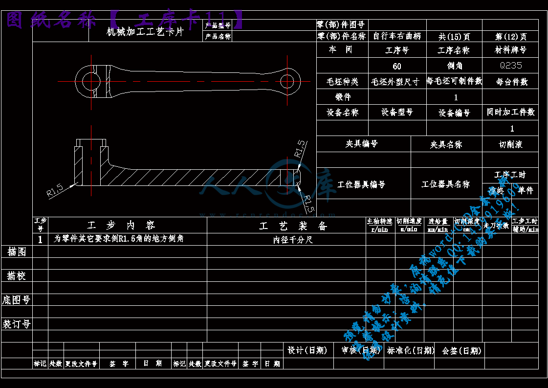
工序卡11.dwg

工序卡12.dwg

工序卡13.dwg

工序卡14.dwg

工艺过程卡片.dwg

开题报告.doc

机床刀具设计外文翻译.doc

毛坯图.dwg

说明书.doc

钻M14x1.25螺纹底孔夹具底座.dwg

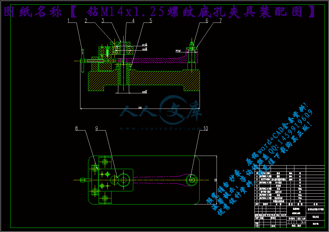
钻M14x1.25螺纹底孔夹具装配图.dwg

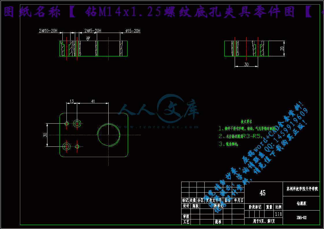
钻M14x1.25螺纹底孔夹具零件图【钻模板】.dwg

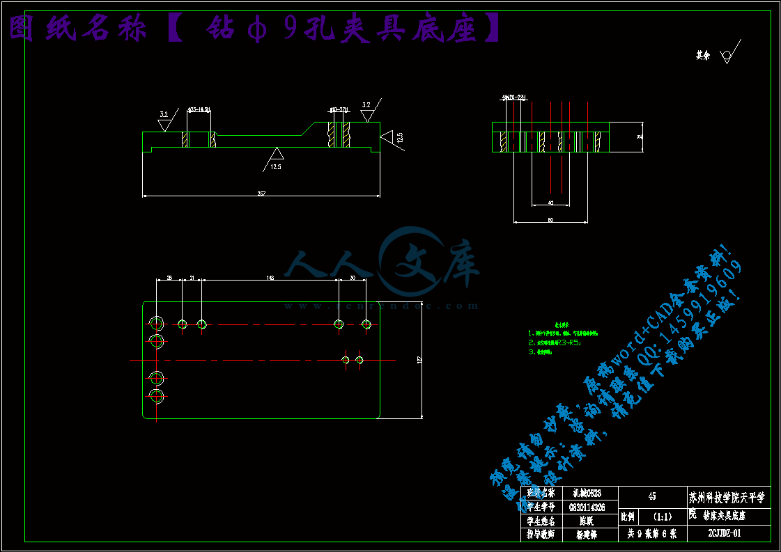
钻φ9孔夹具底座.dwg

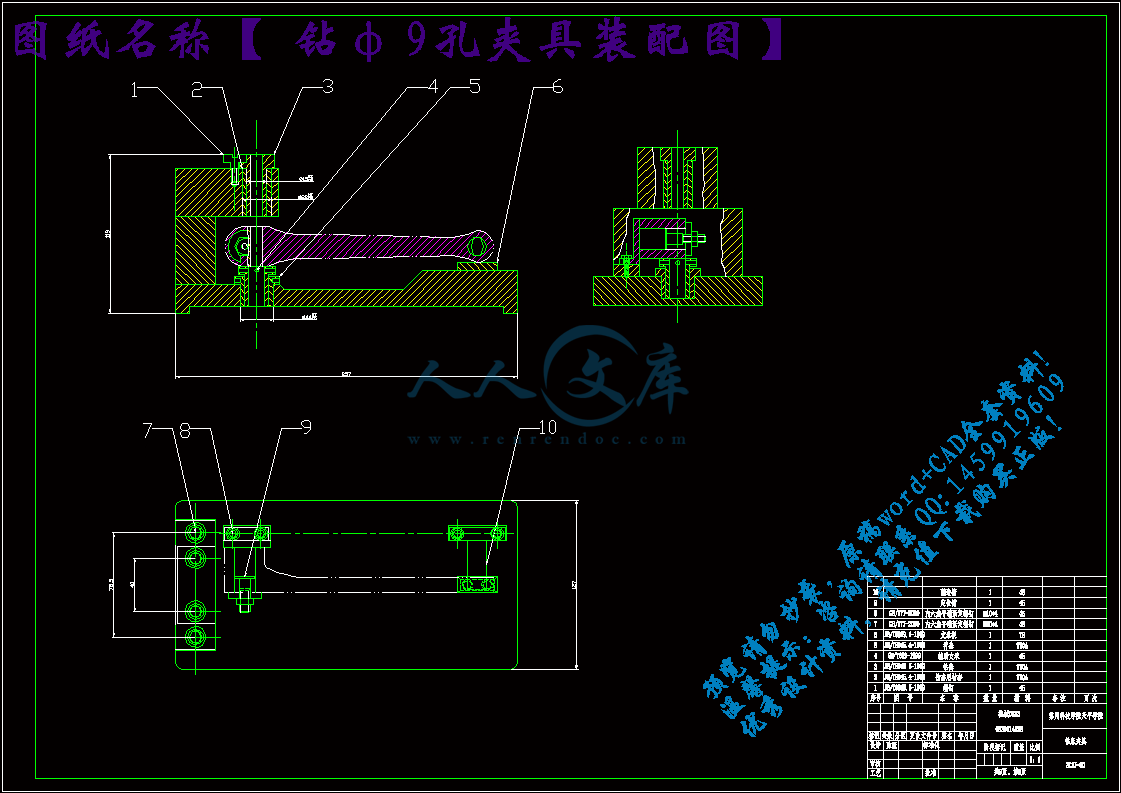
钻φ9孔夹具装配图.dwg

铣削底面夹具底座.dwg

铣削底面夹具装配图.dwg

零件图.dwg

零件图副本.dwg

任务书

1.毕业设计任务的内容和要求(包括技术要求、设计条件、工作要求等):

1、课题的意义

近年来中国制造业快速发展,苏州的机械行业发展得也非常好,急切需要工艺装备方面的人才。根据工厂实际情况,要求工艺技术人员能制定合理的工艺规程,并设计出符合产品技术要求的夹具。

工艺规程的制定与夹具设计,可以使学生得到机械专业知识的系统锻炼。首先,看懂加工零件的零件图需要机械制图和互换性与测量技术两门课的知识;其次制定工艺规程需要机械制造工艺学的知识;夹具设计需要机械制造装备设计的知识;最后还要画出夹具图总装图和重要零件的零件图。

2、设计要求:

(1) 制定出该零件的工艺规程,并做出工序卡片。

(2) 对加工过程中,需要夹具的工序,进行夹具设计

3、知识体系要求

(1) 互换性与测试技术、机械制图、机械CAD、PRO三维绘图;

(2) 机械制造工艺学、机械制造装备设计;

4、需查阅的资料

要求查阅以下几方面的资料:

(1) 互换性与测试技术中关于尺寸公差,形位公差以及粗糙度的知识;

(2) 机械制图中装配图和零件图的绘制方法;

(3) 机械制造工艺学中关于工艺规程制定方面的知识;

(4) 机械制造装备设计中夹具设计部分;

(5) 有关的机械设计手册;

(6) 关于自行车右曲柄工装设计的其他相关资料。    

2.毕业设计应提交的成果(明细列出计算书、设计说明书、图纸、计算成果、硬件实物、实验报告及工作过程中应提交的材料等):

(1) 设计论文一份;

(2) 翻译资料一份;

(3) 夹具设计图纸折合0号图纸不少于1.5张,且60%以上需用计算机绘图。

3.主要参考文献:

[1]胡凤兰主编 . 互换性与测试技术基础 .?北京:高等教育出版社,2005

[2] 裘文言, 张祖继, 瞿元赏主编 . 机械制图 .?北京:高等教育出版社,2003

[3] 王先逵主编 . 机械制造工艺学 .?北京:机械工业出版社,1995

[4] 陈立德主编 . 机械制造装备设计 .?北京:高等教育出版社,2006

摘  要

近年来随着机械行业的飞速发展,机械生产已从传统生产方式向机械自动化方式转换。为保证加工要求,需要设计与加工方式所对应的机床夹具。本次毕业设计研究的对象是自行车曲柄,主要任务是规划加工工艺和设计生产加工所需要的夹具。对于工装设计来说,制定加工工艺规程是非常重要的一步。首先要对曲柄进行全面的分析,确定曲柄的作用和曲柄基本参数。了解曲柄各个表面的加工要求,然后确定曲柄毛坯制造形式,毛坯的制造方式又和零件的材料、形状以及产量等方面因素有关。最后制定生产工序和加工要求。对于本次工装设计制定了三套夹具,包括一套铣床夹具和两套钻床夹具,设计一套夹具首先要考虑的是定位,必须限制所有需要限制的自由度。其次,是夹紧装置的选用,保证零件在加工过程中不受切削力的影响而发生任何方向的移动。同时还要计算夹具的定位误差,确定加工所用的机床和刀具。最后还需要对整个夹具的尺寸、形状和可行性等进行评估。

关键字  曲柄;夹具;加工工艺

Bike right crank tooling design

Abstract

In recent years, with the rapid development of mechanical industry,Machinery production from the traditional production methods to have mechanical automation way conversion.To ensure that the requirements of the processing,Need to design and processing methods corresponding machine tool fixtures.The graduation design research object is a bicycle crank,The main task is planning process and design production processing need fixture.For tooling design example,Make processing technology and procedures are very important step.First to crank on comprehensive analysis,To determine the role of crank and crank basic parameters.Understand each surface processing requirements crank,Then, to determine the crank blank manufacturing form,The manufacture of blank way and parts and materials, shape and production factors, etc.Finally make the production processes and processing requirements.For the tooling design made three sets of fixture,Include a milling machine fixtures and two sets of drilling machine fixture,Design a fixture should consider above all is the positioning,Must limit all need to limit of freedom.secondly,Is the choice of clamping device,Ensure parts in the machining process not by cutting force of the influence of the movement of the direction of any accident.Also the positioning error calculation fixture,Determine the machine tool and tools used processing.Finally also need to the fixture size, shape and feasibility evaluation, etc.

Keywords   crank; fixture;processing technology

目录

第1章   绪论1

1.1 引言1

1.2 机械加工工艺规程的作用1

1.3 机械加工工艺规程的设计原则2

1.4 课题背景及发展趋势3

1.5 本章小结3

第2章  工艺规程设计5

2.1 毛坯的制造形式5

2. 2 零件分析5

2.3 基准的选择6

2.3.1 精基准选择的原则6

2.3.2 粗基准的选择原则7

2.4制定工艺路线8

2.5毛坯尺寸、机械加工余量、工序尺寸的确定9

2.6确定切削用量及基本工时10

2.7 本章小结22

第3章 曲柄的夹具设计24

3.1 铣床夹具设计24

3.1.1 定位装置的设计24

3.1.2 夹紧装置的设计25

3.1.3 铣床夹具的示意图25

3.2钻床夹具设计26

3.2.1定位装置的设计26

3.2.2 夹紧装置的设计27

3.2.3 钻床夹具的示意图28

3.3钻床夹具设计28

3.3.1定位装置的设计29

3.3.2 夹紧装置的设计30

3.3.3 钻床夹具体的示意图30

3.4 本章小结31

结  论32

致  谢33

参考文献34

第1章   绪论

1.1 引言

毕业设计是大学生毕业之前的最后一项重要任务,作为一名机械专业的学生,机械毕业设计是机械工程类专业学生完成本专业学习计划的最后一个极为重要的实践性环节,要求我们能够综合运用所学过的基本理论、基本知识与基本技能去解决专业范围内的工程技术问题而进行的一次基本训练。这对我们即将从事的相关技术工作和未来事业的开拓都具有一定意义。本人此次设计的题目是自行车右曲柄的工装设计,通过本次设计我希望能达到以下几个目的一、锻炼自己综合分析和解决本专业的一般工程技术问题的独立工作能力,拓宽和深化所学的知识。二、树立正确的设计思想,设计构思和创新思维,掌握工程设计的一般程序规范和方法。三、培养自己树立正确的设计思想和使用技术资料、国家标准等手册、图册工具书进行设计计算,数据处理,编写技术文件等方面的工作能力。 四、完善自己进行调查研究,面向实际,面向生产,向同学和老师学习的基本工作态度,工作作风和工作方法。五、认清机械制造业在国民经济中的重要地位,明确我们机械人所肩负着振兴我国机械业的使命。

由于本人水平有限,本说明书难免存一些错误以及不足,希望各位老师和同学提出宝贵的意见和建议。

1.2 机械加工工艺规程的作用

采用机械加工的方法,改变毛坯的形状、尺寸、相互位置关系和表面质量,使其成为可完成某种使用要求的零件的过程,称为机械加工工艺规程。工艺规程一般包括以下几个重要方面:

1) 工艺规程是指导生产的主要技术文件

机械加工车间生产的计划、调度,工人的操作,零件的加工质量检验,加工成本的核算,都是以工艺规程为依据的。处理生产中的问题,也常以工艺规程作为共同依据。如处理质量事故,应按工艺规程来确定各有关单位、人员的责任。

2) 工艺规程是生产准备工作的主要依据

车间要生产新零件时,首先要制订该零件的机械加工工艺规程,再根据工艺规程进行生产准备。如:新零件加工工艺中的关键工序的分析研究;准备所需的刀、夹、量具(外购或自行制造);原材料及毛坯的采购或制造;新设备的购置或旧设备改装等,均必须根据工艺来进行。

3) 工艺规程是新建机械制造厂(车间)的基本技术文件

新建(改.扩建)批量或大批量机械加工车间(工段)时,应根据工艺规程确定所需机床的种类和数量以及在车间的布置,再由此确定车间的面积大小、动力和吊装设备配置以及所需工人的工种、技术等级、数量等。

此外,先进的工艺规程还起着交流和推广先进制造技术的作用。典型工艺规程可以缩短工厂摸索和试制的过程。因此,工艺规程的制订是对于工厂的生产和发展起到非常重要的作用,是工厂的基本技术文件。

1.3 机械加工工艺规程的设计原则

设计机械加工工艺规程应遵循如下原则:

1)可靠地保证零件图样上所有技术要求的实现。在设计机械加工工艺规程时,如果发现图样上某一技术要求规定得不适当,只能向有关部门提出建议,不得擅自修改图样或不按图样上的要求去做。

2)必须能满足生产纲领的要求。

3)在满足技术要求和生产纲领要求的前提下,一般要求工艺成本最低。

4)尽量减轻工人的劳动强度,保障生产安全。

同时制定工艺规程时必须具备下列原始材料:

1)产品的全套技术文件,包括产品的全套图纸、产品的验收质量标准以及产品的生产纲领。

2)毛坯图及毛坯制造方法。工艺人员应研究毛坯图,了解毛坯余量,结构工艺性,以及锻件分型面,浇口、冒口的位置,以及正确的确定零件的加工装夹部位及方法。

3)车间的生产条件。即了解工厂的设备、刀具、夹具、量具的性能、规格及精度状况;生产面积;工人的技术水平;专用设备;工艺装备的制造性能等。

4)各种技术资料。包括有关的手册、标准、以及国内外先进的工艺技术等。

1.4 课题背景及发展趋势

随着科技技术的不断发展,机械制造业的生产模式发生了巨大的改变,械制备的发展呈如下趋势;

1)向高效、高速、高精度方向发展

2)多功能复合化、柔性自动化的产品成为发展主流

3)实施绿色制造与可持续发展战略

4)智能制造技术和智能化装备快速发展

为适应生产发展的需要,当前自控机构、机器人机构、仿生机构、柔性及弹性机构和机电光液综合机构等的研制有了很大进展。在机械的分析与综合中,也有只考虑其运动性能过渡到同时考虑其动力性能,考虑记协在运转时的构件振动和弹性变形、运动服的间隙和构件的误差对机械运动及动力性能的影响,以及如何对构件和机械进一步做好动力平衡的问题等等。

尽管,自行车曲柄作为一个传统零件,技术相对成熟,但我们仍然必须看到其潜在的发展空间。比如,选材方面,是否可以选用新型材料从而减轻重量而改善质量。加工方面,是否能够改变传统的生产模式从而提高生产效率而增加收益。发展研究方面,是否能够通过进一步完善其形状、尺寸等从而使产品设计更加人性化。

目前,在机械的分析和综合中日益广泛地应用了计算机技术,发展推广了计算机辅助设计、优化设计、考虑误差的概率设计,提出了多种便于机械经分析和综合的工具。编制了许多大型通用或专用的计算机程序。

1.5 本章小结

随着机械业的不断发展,我们应该深刻认识到机械制造工业在发展国民经济中的地位与作用,作为一名机械毕业生,我们要了解我国在机械制造行业方面所取得的成绩和当前存在的主要问题,以及制造技术发展的方向。熟悉生产过程和工艺过程的概念。了解工艺过程每个组成的定义,树立远大的理想,为我国的机械行业做出自己的贡献。

第2章  工艺规程设计

2.1 毛坯的制造形式

按照设计任务书,本次设计的自行车类型年产量为10000辆,其上有左、右曲柄各一个。若右曲柄的备品率为8%,机械加工废品率为1%,则该零件的年生产纲领为:

件/年

可见,右曲的年产量为10908件。自行车右曲柄可以看成是独立的一部分,属于轻型机械,由此,根据《机械设计制造技术基础课程设计指导教程》表1-4,由生产纲领与生产类型的关系可以确定该零件的生产为大批生产。由该零件的功用及自行车的工作状况知,该零件需要具备较高的强度,所以选择碳素钢材料,它不仅能满足强度要求同时价格低廉。因此可以确定毛坯的制造形式为锻造。由于该曲柄成批生产,根据《机械设计制造技术基础课程设计指导教程》表2-1可知。

2. 2 零件分析

1)了解零件用途

设计工艺规程时,首先应分析零件图纸以及该零件所在部件或总成的装配图,掌握该零件在部件或总成中得位置、功能以及部件或总成对该零件提出的技术要求,明确零件的主要工作表面,以便在拟定工艺规程时采取措施予以保证。

2)分析零件的技术要求

从零件图上可以看出标有表面粗糙度的有平面、外圆端面、内孔等。其中,表面粗糙度要求最高的是孔,公差等级达到IT7级,表面粗糙度为,该孔是右曲柄的主要设计基准从表面间的位置精度要求来看,与孔中心线平行度公差为,与孔对底面垂直度公差为。

3)审查零件工艺性

审查零件图样上的视图、尺寸公差和技术要求是否正确、统一、完整、审查零件的结构工艺,是否有利于机械加工、装配、热处理以及毛坯制造等方面。

对右曲柄零件图进行工艺审核后,可知该零件图视图正确、完整,尺寸、公差技术要求齐全,加工要求合理,零件的结构工艺性较好。

2.3 基准的选择

用来确定生产对象几何要素间几何关系所依据的点、线、面,称为基准,基准又分为设计基准和工艺基准两类。拟定工艺路线的第一步是选择定位基准。

参考文献

[1] 杨沿平,机械精度设计与检测技术基础[M] ,北京:机械工业出版社,2004。

[2] 陈立德,机械制造装备设计,北京:高等教育出版社,2006。

[3] 李昌年,机床夹具设计与制造[M] ,北京:机械工业出版社,2006。

[4] 刘友才,机床夹具设计[M] ,北京:机械工业出版社,1992 。

[5] 孟少龙,机械加工工艺手册第1卷[M],北京:机械工业出版社,1991。

[6] 《金属机械加工工艺人员手册》修订组,金属机械加工工艺人员手册[M],上海:上海科学技术出版社,1979。

[7] 李洪,机械加工工艺师手册[M],北京:机械工业出版社,1990。

[8] 马贤智,机械加工余量与公差手册[M],北京:中国标准出版社,1994。

[9] 上海金属切削技术协会,金属切削手册[M],上海:上海科学技术出版社,1984。

[10] 周永强,高等学校毕业设计指导[M],北京:中国建材工业出版社,2002。

[11] 薛源顺,机床夹具设计(第二版) [M],机械工业出版社,2003.1

[12] 余光国,马俊,张兴发,机床夹具设计[M],重庆:重庆大学出版社,1995。

[13] 东北重型机械学院,洛阳农业机械学院,长春汽车厂工人大学,机床夹具设计手册[M],上海:上海科学技术出版社,1980。

[14] 李庆寿,机械制造工艺装备设计适用手册[M],银州:宁夏人民出版社,1991。

[15] 乐兑谦,金属切削刀具,机械工业出版社,2005:4-17。

[16] 杨翟,陈国香,机械制造与模具制造工艺学,北京:清华大学出版社,2006

内容简介:
苏州科技学院天平学院毕业设计任务书设计题目 自行车右曲柄工装设计 院 (系) 机电工程系专 业 机械设计制造及其自动化学生姓名 学 号 起迄日期 2012年 2月13日 2012 年 6月10日 设计地点 指导教师 杨建锋 职称 讲师职称填写日期: 2012 年 1月 10 日1毕业设计任务的内容和要求(包括技术要求、设计条件、工作要求等):1、课题的意义近年来中国制造业快速发展,苏州的机械行业发展得也非常好,急切需要工艺装备方面的人才。根据工厂实际情况,要求工艺技术人员能制定合理的工艺规程,并设计出符合产品技术要求的夹具。工艺规程的制定与夹具设计,可以使学生得到机械专业知识的系统锻炼。首先,看懂加工零件的零件图需要机械制图和互换性与测量技术两门课的知识;其次制定工艺规程需要机械制造工艺学的知识;夹具设计需要机械制造装备设计的知识;最后还要画出夹具图总装图和重要零件的零件图。2、设计要求: (1) 制定出该零件的工艺规程,并做出工序卡片。(2) 对加工过程中,需要夹具的工序,进行夹具设计3、知识体系要求(1) 互换性与测试技术、机械制图、机械CAD、PRO三维绘图; (2) 机械制造工艺学、机械制造装备设计;4、需查阅的资料要求查阅以下几方面的资料:(1) 互换性与测试技术中关于尺寸公差,形位公差以及粗糙度的知识;(2) 机械制图中装配图和零件图的绘制方法;(3) 机械制造工艺学中关于工艺规程制定方面的知识;(4) 机械制造装备设计中夹具设计部分;(5) 有关的机械设计手册;(6) 关于自行车右曲柄工装设计的其他相关资料。 2毕业设计应提交的成果(明细列出计算书、设计说明书、图纸、计算成果、硬件实物、实验报告及工作过程中应提交的材料等):(1) 设计论文一份;(2) 翻译资料一份;(3) 夹具设计图纸折合0号图纸不少于1.5张,且60%以上需用计算机绘图。3主要参考文献:1胡凤兰主编 . 互换性与测试技术基础 .北京:高等教育出版社,20052 裘文言, 张祖继, 瞿元赏主编 . 机械制图 .北京:高等教育出版社,20033 王先逵主编 . 机械制造工艺学 .北京:机械工业出版社,19954 陈立德主编 . 机械制造装备设计 .北京:高等教育出版社,20064毕业设计工作进度安排:(包括序号、起迄日期、工作内容):2012-02-15至2012-03-11 查阅资料, 撰写开题报告,翻译外文资料2012-03-12至2012-04-09 完成工艺规程制定中的计算部分,填写工艺规程卡片2012-04-10至2012-05-06 设计夹具总装图和零件图2012-05-07至2012-06-01 撰写论文,打印图纸,提交设计材料2012-06-02至2012-06-10 准备答辩指导教师签字: 教研室/系 主任签字: 年 月 日 苏州科技学院天平学院毕业设计(论文)开题报告论文题目 自行车右曲柄工装设计 院 (系) 机电工程系 专 业 机械设计制造及其自动化 学生姓名 XX 学 号 指导教师 杨建锋 2012年 3 月 1 日1本课题研究的背景、目的及意义研究的背景:自行车是人类历史上一项伟大的发明,它改变了人类代步需要借助外力的束缚。尽管随着社会的发展人们代步的工具越来越多,但自行车因为其自身方便灵巧,绿色环保等多种优点而依然被广泛使用,而自行车曲柄则是驱动系统中的主要部件之一。自行车曲柄的作用:1.曲柄和脚蹬、中轴、链轮、链条、飞轮、后轴、后轮等部件组成了自行车的驱动系统,人的脚的蹬力是靠脚蹬通过曲柄,链轮、链条、飞轮、后轴等部件传动的,从而使自行车不断前进。2.曲柄应用了物理学上的杠杆原理,减轻了人们驾车的疲劳,是一项巧妙的设计。自行车曲柄分为左右两个,由于加工过程方法类似,所以本次设计只取右曲柄作为研究设计对象。研究的目的及意义:我国是一个自行车使用的大国,自行车的需求量依然很大。近年来中国制造业发展迅速,生产自动化水平越来越高,机械制造业在国民经济中占有比例也随之提高,而像自行车上的普通零件也由传统的生产方式转向机械自动化生产。机械制造技术是机械制造企业实现产品设计,完成产品生产,保证产品质量,提高经济效益的共性技术和基础技术。在全球范围内,机械制造技术正朝着精密化、自动化、敏捷化和可持续发展的方向发展。由此对机械工艺装备制造方面的人才的需求也是特别的大,对于工厂实际的制造要求,需要工艺制造人员合理的安排工艺规程,并且设计制造出符合产品技术要求的夹具。从而在最短的时间内生产多更多的产品,创造更多的收益。通过此次对自行车右曲柄的工艺制定及夹具的设计,进一步肯定了机械制造工业在发展我国国民经济中的地位与作用,我国现代化建设的发展速度在很大的程度上取决于机械装备制造业的发展水平,从这个意义上说,加快振兴机械装备制造业是至关重要的。同时,充分融合四年所学的机械设计制造方面的专业知识以及实践、实习所得到的经验。从而锻炼自己对具体机械制造问题的分析,解决能力。使得具备制定中等复杂程度零件的工艺规程和设计针对工件工艺加工所需的夹具的能力其次也锻炼了自己查找资料文献的能力以及各种机械辅助软件的操作和使用。2本课题主要研究内容和预期目标研究的内容:本课题的主要研究内容为,采用机械加工的方法,改变毛坯的形状、尺寸、相互位置关系和表面质量,使其成为可完成某种使用要求的零件过程,即制定自行车右曲柄机械加工工艺规程的制定。同时为保证加工精度,提高生产效率,减轻劳动强度,适应自动化生产设计切实可行的机床夹具。研究的预期目标:本课题的预期目标为,通过对零件图的分析,掌握该零件在整个部件中得位置,功用以及部件或总成对该零件提出的技术要求,明确零件的主要工作表面,以便在拟定工艺规程时采取措施予以保证,统筹安排生产工序,确保工艺规程的合理,省时。根据零件要求的加工误差,生产规模制定出的夹具要能够保证具有足够刚度、强度、稳定性以及良好的工艺性。3本课题拟采用的研究方法、步骤研究的方法:本课题主要采用计算法,分析法,文献检索法,AutoCAD机械制图法。研究的步骤:1.机械加工工艺规程的步骤1)根据零件图和产品装配图,对零件进行工艺分析2)计算零件的生产纲领,确定生产类型3)确定毛坯的种类和制造方法4)确定毛坯的尺寸和公差5)拟定工艺路线6)确定各工序的加工余量,计算工序尺寸及公差7)选择各个工序的机床设备及刀具,量具及工艺装备8)确定各个工序的切削用量和时间定额9)编制工艺文件2.夹具设计步骤:1)分析零件图纸2)确定夹具的结构方案3)绘制夹具的装配草图和装配图4) 绘制夹具零件图5)编写夹具设计说明书3.具体工艺方案工艺方案一:工序1 锻造。工序2 粗车零件顶面。工序3 粗铣零件底面。工序4 粗铣零件前后两端面。工序5 钻mm的孔。工序6 铰mm的孔。工序7 钻17mm的孔。工序8 钻mm的螺纹孔。工序9 攻mm的螺纹。工序10 钻mm的孔。工序11 铰mm的孔。工序12 粗车mm孔的外端面。工序13 半精车mm孔的外端面,并倒角。工序14 为其它要求倒角的边倒角。工序15 去毛刺,表面镀铬,清洗。工序16 终检。工艺方案二:工序1 锻造。工序2 粗车零件顶面。工序3 粗铣零件底面。工序4 粗铣零件前后两端面。工序5 钻mm的螺纹孔。工序6 攻mm的螺纹。工序7 钻mm的孔。工序8 铰mm的孔。工序9 钻17mm的孔。粗铰,精铰mm的孔。工序10 粗车mm孔外端面。工序11 半精车mm孔的外端面,并倒角。工序12 钻mm的孔。工序13 铰 mm的孔。工序14 为所有其它要求倒R1.5角的边倒角。工序15 去毛刺,表面镀铬,清洗。工序16 终检。上述两个方案的差别在于,方案一是以mm孔为中心进行加工的,方案二是以mm的螺纹孔为中心进行加工的。由于mm孔是整个零件加工精度要求最高的,所以方案一选取它作为中心进行加工,能够保证零件的整个加工精度要求。同时方案二在还没有对mm孔进行加工时,先对mm孔的外端面进行了加工,这样就增加了mm孔加工定位误差。所以最终从加工精度要求方面考虑选择工艺方案一比较的合理。4本课题主要参考文献1 周宏甫.机械制造技术基础.北京:高等教育出版社,2004;2 张普礼.机械加工工艺装备.南京:东南大学出版社,1995;3 哈尔滨工业大学,上海工业大学.机床夹具设计.上海:上海科学技术出版社,1989;4 刘友才,肖继德.机床夹具设计.北京:机械工业出版社,1997;5 刘茂元.机械制造技术.北京:机械工业出版社,2001;6 郑修本.机械制造工艺学.北京:机械工业出版社,2000;7 李庆余.机械制造装备设计.北京:机械工业出版社,2003;8 黄鹤汀.机械制造装备.北京:机械工业出版社,2001;9 刘守勇.机械制造工艺与机床夹具.北京:机械工业出版社,2004;10 王先逵.机械加工工艺手册.北京:机械工业出版社;11 李昌年.机床夹具设计与制造.北京:机械工业出版社;12 张德泉.机械制造装备及其设计.天津:天津大学出版社;13 邹青.机械制造技术基础课程设计指导教程. 北京:机械工业出版社;14 吴拓,方琼珊.机械制造工艺与机床夹具课程设计指导. 北京:机械工业出版社。5 本课题的具体进度安排(包括序号、起迄日期、工作内容)2012-02-13至2012-03-11 查阅资料, 撰写开题报告,翻译外文资料2012-03-12至2012-04-08 完成工艺规程制定中的计算部分,填写工艺规程卡片2012-04-09至2012-05-06 设计夹具总装图和零件图2012-05-07至2012-05-27 撰写论文,打印图纸,提交设计材料2012-05-28至2012-06-03 准备答辩 指导教师意见: 指导教师: 年 月 日附录A 译文机床刀具设计课题研究意义:机床原来的刀库控制程序是单独设计的,没有采用刀具管理系统,功能也比较单一,只实现了刀库刀具的找刀、刀库最短路径定位、主轴换刀,而且不支持大型刀具。在刀库自动选刀方面,在计算机记忆式选刀的基础上采用了西门子840D特色功能,使选刀程序更简洁,并完成空刀套的查找。刀库快速换刀利用STEP-7完成编程,并在实际中得到验证。在刀库定位问题上,PLC程序控制采用模块化设计方法,这对今后生产类似机床将十分有利,很容易将其利用到其他机床上。自动换刀系统将以较快的速度增长,缩短换刀时间,提高刀具的定位精度是重要的手段,有利于数控技术的发展。刀具及其元件库存是现代生产管理中的重要环节, 特别是大型车间管理。传统的人工记帐管理方式, 效率低下, 错误率高, 且信息数据不能共享, 刀具的使用状态和寿命周期无法跟踪, 不能适应当前信息化管理需要。结合生产实际, 我们在车间刀具准备间建立刀具贮存立体库系统, 以满足车间刀辅具储存与管理的需要。该系统采用最优化技术, 利用计算机存储的大量库存信息, 能及时、准确、全面地反映刀具库的库存情况。整个系统采用图形界面, 人机对话由中文菜单提示, 可实现各种功能选择和各种信息的输入。管理系统采用在线帮助功能。可通过车间管理层、网络系统实现信息管理和共享。具有自动库存管理、刀具入库管理、刀具出库管理和统计查询功能。1.系统组成及其控制结构整个系统包括机械结构及电气控制系统。1.1.1 机械结构及工作原理刀具库由支架、驱动机构、传动系统、刀架、护罩、电气控制系统等部分组成。支架由立柱、横梁、上下导向环轨、支撑地轨组成。1)驱动机构该系统选用了变频调速的方法。采用锥形制动电机, 带变频调速, 经摆线针轮减速器, 通过链轮传动。2)拖动与传动系统采用变频控制技术。通过变频调速, 可使传动轴转速在正常范围内调节使刀架回转速度控制到 5 30mm in, 2 个传动轴各带上、下2 个链轮通过上、下2 条异形滚子链带动货架转动。链条胀紧机构采用螺纹调节胀紧, 为定期胀紧方式。调节时上、下链条松度调节一致, 使链条受力均匀。3)刀架与防护罩整库共有14 列独立刀架。其中 13 列为插座式刀架, 1 列为抽屉式刀架, 每个刀架背部通过销轴与上、下输送链链板联接, 底部安装滚轮, 链条转动带动刀架沿地轨转动。插座式刀架分BT40 刀架和BT50 刀架 2 种形式。为加强管理, 保证安全, 美化造型, 货架外围加防护罩。抽屉式刀架分 6 个抽屉放置其他刀辅具, 可分类装存一些刀辅具, 如钻头、车刀等。1.1.2. 电气控制系统本刀具储存系统的电气控制主要是对其货架进行运行控制和位置控制。运行控制包括运行设备的启动、制动控制。位置控制主要是对货架位置和地址进行检测。控制系统框图如图 1 所示。图 1刀具库控制系统图1)电气传动水平旋转刀具储存系统各机械的动作都属于反复短时工作制。而且系统在运行时需要几种速度, 因此传动系统需要调速, 所以该系统选用了变频调速的方法, 可以采用结构简单、运行可靠的变频器和变频电动机。2)控制方式该系统分为手动和自动控制2 种控制方式, 手动控制一般作为调试用和备用的工作方式; 自动控制方式为本系统计算机(IPC)和控制单元(变频器、接触器等)组成的一个自动控制系统。3)位置及定位精度检测本系统中自动认址和位置检测采用了接近开关作为检测元器件, 通过光点隔离继电器板和记数板对接近开关采集的信号进行记数和运算处理, 采用最优路径寻址方式确定货架的当前位置和货架的目的位置。为了使系统定位更准确, 采用了 2 只光电开关, 分别检测2 个货架的2 只检测片。1.2.刀库的功能刀库的作用是储备一定数量的刀具,机械手实现主轴上刀具的互换zsa刀具的类型有盘式刀库、链式刀库等多种形式,刀库的形式和容量要根据机床的工艺范围来确定。1.3.常见类型 刀库是存储刀具的装置,常见的刀库主要有以下几种形式:(1)转塔式刀库包括水平转塔头和垂直转塔头两种,见图2.6a)与b): (2)盘式刀库盘式刀库中刀库呈盘状,刀具沿盘面垂直排列(包括径向取刀和轴向取刀),沿盘面径向排列或成锐角排列的形式的刀库。结构简单、紧凑,应用较多,但刀具单环排列,空间利用率低。见图2.7a)c)。若增加刀库容量必须使刀库的外径增大,那么转动惯量也相应增大,选刀运动时间长。刀具数量一般不多于32把。刀具呈多环排列的刀库的空间利用率高,但必然使得取刀机构复杂,适用于机床空间受限制而刀库容量又较大的场合。双盘式结构是两个较小容量的刀库分置于主轴两侧,布局较紧凑,储刀数量也相应增大,适用于中小型加工中心。(3)链式刀库 包括单环链和多环链,链环形式可有多种变化,见图2.8a)c),基本结构见图2. 8do特点:适用于刀库容量较大的场合,所占的空间小,一般适用于刀具数在30-120把。仅增加链条长度即可增加刀具数,可以不增加圆周速度其转动惯量不像盘式刀库增加的那样大。(4)直线式刀库和组合刀库直线式刀库结构简单如图2. 9,刀具单行排列,刀库容量小,多用于数控车床和钻床上。由于刀库位置固定,换刀动作由主轴完成,无需机械手。组合刀库一般是转塔式刀库的组合、转塔式与盘式刀库的组合及链式刀库的组合。每单个刀库的储刀量较小,换刀速度快。另外还有一些密集型的鼓轮式、弹匣式和格子式刀库,这些密集型刀库虽.占地面积小,但由于结构限制,基本上不用于单机加工中心,多用于FMS的集中供刀系统。1.4.刀库的容量刀库的容量首先要考虑加工工艺的需要,从使用角度出发,一般为1040把刀,刀库的利用率会高,而结构比较紧凑。1.5.刀具的选择方式(1)顺序选择将刀具按加工工序的顺序,依次放入刀库的每一个刀座内。每次换刀时,刀库顺序转动一个刀座位置,并取出所需要的刀具,己经使用过的刀具可以放回原来的刀座内,也可以顺序放入下一个刀座内。但由于刀库中刀具在不同的工序中不能重复使用,必须增加刀库的容量,降低了利用率。(2)任意选择目前大多数的数控系统都采用任意选刀的方式,其分为刀套编码、刀具编码和记忆式等三种。刀具编码或刀套编码需要在刀具或刀套上安装用于识别的编码条,一般都是根据二进制编码的原理进行编码。刀具编码选刀方式采用了一种特殊的刀柄结构,并对每把刀具编码。每把刀具都具有自己的代码,因而刀具可在不同的工序中多次重复使用,换下的刀具不用放回原刀座,刀库的容量也可相应减少。本文采用记忆式选刀,这种方式能将刀具号和刀库中的刀套位置对应地记忆在数控系统的PLC中,无论刀具放在哪个刀套内,刀具信息都始终记存在PLC内。刀库上装有位置检测装置,可获得每个刀套的位置。这样刀具就可以任意取出并送回。刀库上还设有机械原点,使每次选刀时就近选取。1.6.刀库的控制方式 (1)刀库作为系统的定位轴来控制。在梯形图中根据指令的T码进行运算比较后输出角度和速度指令到刀库伺服驱动刀库伺服电机。刀库的容量、旋转速度、加/减速时间等均可在系统参数中设定,此种方式不受外界因素影响定位准确、可靠但成本较高。 (2)刀库由液压马达驱动,有快/慢速之分,用接近开关计数并定位。在梯形图中比较系统存储的当前刀号(主轴上的刀)和目标刀号(预选刀)并运算,再输出旋转指令,同时判断按最短路径旋转到位。这种方式需要足够的液压动力和电磁阀刀库旋转速度可通过节流阀调整。但使用一段时间后可能会因为油质、油压、油温及环境因素的变化而影响运动速度和准确性。一般用于不需频繁换刀的大中型机床。 (3)刀库由交流异步电动机驱动凸轮机构(马氏机构),用接近开关计数,这种方式运行稳定,定位准确可靠一般与凸轮机械手配合使用,换刀速度快,定位准。2.换刀装置的主要类型,特点和适用范围2.1.自动回转刀架自动回转刀架是数控机床上使用的一种简单的自动换刀装置,有四方刀架和六角刀架等多种形式,回转刀架上分别安装有四把、六把或更多的刀具,并按数控指令进行换刀。回转刀架又有立式和卧式两种,结构比较简单,适用于经济数控车床。回转刀架在结构上必须具有良好的强度和刚度,以承受粗加工时切削抗力和减少刀架在切削力作用下的变形,提高加工精度。回转刀架还要选择可靠的定位方案和合理的定位结构,以保证回转刀架在每次转位之后具有较高的重复定位精度(一般为0.001 0.005mm )。图2.1所示为螺旋升降式四方刀架。在自动回转刀架中最简单的换刀装置是180回转式换刀装置,如图2.2所示。接到换刀指令后,机床控制系统便将主轴控制到指定换刀位置;与此同时,刀具库运动到适当位置,换刀装置回转并同时与主轴、刀具库的刀具相配合;拉杆从主轴刀具上卸掉,换刀装置将刀具从各自的位置上取下;换刀装置回转180并将主轴刀具与刀具库刀具带走;换刀装置回转的同时,刀具库重新调整其位置,以接受从主轴取下的刀具;接下来,换刀装置将要换上的刀具与卸下的刀具分别装入主轴和刀具库:最后,换刀装置转回原“待命”位置。至此,换刀完成,程序继续运行。这种换刀装置的主要优点是结构简单、涉及的运动少、换刀快。主要缺点是刀具必须存放在与主轴平行的平面内,与侧置后置刀具库相比,切屑及切削液易进入刀夹,因此必须对刀具另加防护。刀夹锥面上有切屑会造成换刀误差,甚至有损坏刀夹与主轴的可能。有些加工中心使用了传递杆,并将刀具库侧置。当换刀指令被调用时,传递杆将刀具库的刀具取下,转到机床前方,并定位于与换刀装置配合的位置。180“回转式换刀装置既可用于卧式机床,也可用于立式机床。2. 2.转塔头式换刀装带有旋转刀具的数控机床常采用此种换刀装置,转塔头上装有几个主轴,每个主轴上均装一把刀具,加工过程中转塔头可自动转位实现换刀。其优点是结构简单,换刀时间短,仅为2s左右。但由于受空间位置的限制,主轴数目不能太多,通常只适用于工序较少、精度要就不高的机床,如数控钻床、数控铣床等。近年来出现了一种用机械手和转塔头配合刀库进行换刀的自动换刀装置,如图2.3所示。它实际上是转塔头换刀装置和刀库式换刀装置的结合。其原理如下:转塔头5上有两个刀具主轴3和4,当用刀具主轴4上的刀具进行加工时,可由机械手2将下一步需要的刀具换至不工作的刀具主轴3上,待本工序完成后,转塔头回转180,完成换刀。因其换刀时间大部分和加工时间重合,真正换刀时间只需转塔头转位的时间,这种换刀方式主要用于数控钻床和数控锉床等。2. 3.带刀库的自动换刀系统图2.4所示为刀库与机床为整体式数控机床的外观图。图2.5所示为刀库与机床为分体式数控机床的外观图。此时,刀库容量大,刀具可以较重,常常附加运输装置来完成刀库与主轴之间刀具的运输。带刀库的换刀装置由刀库、选刀机构、刀具自动装卸机械及刀具交换机构(机械手)等四部分组成,应用广泛。刀库机械手自动换刀系统,整个换刀过程比较复杂。首先要把加工过程中使用的全部刀具安装在标准刀柄上,在机外进行尺寸预调后,按一定的方式放入刀库。换刀时,先在刀库中选刀,再由换刀装置从刀库或主轴上取刀,进行交换,将新刀装入主轴,旧刀放回刀库。 由于前两种换刀装置容纳的刀具数量有限不能太多,不能满足复杂零件的加工需要,所以自动换刀数控机床多采用带刀库的自动换刀装置。刀库具有较大容量,既可安装在主轴箱的侧面或上方。由于带刀库的自动换刀装置的数控机床的主轴箱内只有一根主轴,主轴部件的刚度要高,以满足精密加工要求。刀库内数量较大,因而能满足复杂零件的多工序加工,大大提高生产率。带刀库的自动换刀系统适用于数控钻削中心和加工中心。进行比较得出带刀库的自动换刀系统是最有发展前景的。3.PLC控制的随机选刀方式的研究3. 1常见的自动选刀方式刀库的自动控制指CNC执行用户指令后系统对刀库的自动控制过程,包括程序找刀和自动换刀(63,71。加工中心的计算机数控装置(CNC)发出的选刀指令,将刀库转到所需刀具号的取刀位置,称自动选刀。自动选刀有两种方法:顺序选刀和随机选刀方法。3.1.1顺序选刀 顺序选刀方法是刀具按预定工序的先后顺序插入刀库中,使用时按顺序转到取刀位置,用过的刀具放回原来的刀座内,也可以顺序放入下一个刀座内。采用这种方式,不需要刀具识别装置,而且驱动装置控制也比较简单,工作可靠,可以直接由刀库的分度机械来实现。但刀库中每把刀具在不同的工序中不能重复使用,如果刀具不按顺序装在刀库中,将会产生严重的后果。必须增加刀具的数量和刀库的容量,降低了刀具和刀库的利用率。3.1.2随机选刀 随机选刀方法是根据指令要求任意选择所需要的刀具,这时必须有刀具识别装置。刀具在刀库中不必按照工件的加工顺序排列,可任意存放的。每把刀具(或刀座)均编上代码,自动换刀时,刀库旋转,每把刀具都经过“刀具识别器”接受识别。当刀具代码与CNC指令代码相符时该刀具被选中刀库旋转将刀具送到换刀位置,等待机械手来抓取。随机选刀的优点是刀库中刀具的排列顺序与加工顺序无关,相同的刀具可以重复使用。因此,刀具数量比较少,刀库也相应的较小。随机选刀必须对刀具编码,以便识别。编码主要有以下三种。1.刀具编码方式。采用特殊的刀柄结构进行编码,刀柄后端的拉杆上套装着等间距的编码环,由锁进螺母固定。编码环直径有大小直径两种,分别表示二进制的“1”和“0,通过这两个圆环的不同排列,可以得到一系列代码。例如有六个大小直径的圆环便可组成能区别63 ( 26-1=63)种刀具的编码。通常全为0的代码不许使用,以避免与刀座中没有刀具的状况混淆。2.刀座编码方式。对刀座编码,刀具编码,并将刀具放到与其号码相符的刀座中。换刀时刀库旋转,使每个刀座位依次经过识刀器,找到刀座,刀库便停止旋转。这时刀柄上没有了编码环,使刀柄简化。3.编码附件方式。这种方式有编码钥匙、编码卡片、编码杆和编码盘等,其中应用最多的是编码钥匙。先给刀具都附上一把裹示该刀具号的编码钥匙,当把各刀具存放到刀库的刀座中时,这样就把钥匙的号码转记道刀座中,将编码钥匙插进到座旁边的钥匙孔中给刀座编上了号码。 结语重点讨论了在当今制造环境下刀具存储与管理新的模式和方法, 实际应用效果良好, 在系统集成和优化运行等方面将进一步探讨, 使之具有更高理论和实际水平。附录B Design Of Tool Machine PropResearch significanceThe original knife machine control procedures are designed individually, not used tool management system, features a single comparison, the knife only has to find the tool knife, knife positioning the shortest path, axis tool change, but does not support large-scale tool. Automatic knife in the knife election, in the computer memory knife-election on the basis of using the Siemens 840 D features, and the election procedures knife more concise, and complete the space Daotao View. ATC use the knife rapid completion of STEP-7 programming, and have been tested in practice. In the positioning of the knife, PLC controlled modular design method, which future production of similar machines will be very beneficial, it is easy to use its other machine. Automatic tool change systems will be faster growth, reduced tool change time, increase the positioning accuracy tool is an important means to help NC technology development. Tool and inventory components of modern production is an important link in the management, especially for large workshop management. The traditional way of account management, and low efficiency, high error rate, and not sharing information and data, tools and the use of state can not track the life cycle, are unable to meet the current information management needs. With actual production, we have to establish a workshop tool for the three-dimensional tool storage system to meet the knife workshop with auxiliary storage and management needs. The system uses optimization technology, a large number of computer storage inventory information, timely, accurate, and comprehensive tool to reflect the inventory situation. The entire system uses a graphical interface, man-machine dialogue tips from the Chinese menu, select various functions can be realized and the importation of all kinds of information. Management system using online help function. Through the workshop management, network management and sharing of information. Have automated inventory management, warehousing management tool, a tool for the management and statistical functions.1.System components and control structureThe entire system, including the structure and electrical machinery control systems.1.1.1Mechanical structure and working principleTool from the stent, drive, drive system, Turret, shielding, control system, and electrical components. Support from the column, beam, the upper and lower guide Central track, and track support component. 1) Drive for the system chosen VVVF method. Cone used brake motors, with VVVF by Cycloid reducer through sprocket drive. 2) Drag a variable frequency drive system and control technology. VVVF adopted, will speed drive shaft in the normal range adjustment to control the speed rotary turret to 5 30mm in, the drive shaft into two, two under through sprocket, the two profiled rollers Chain driven rotating shelves. Expansion chain adopted by the thread tight regulation swelling, swelling the regular way. - Conditioned, under the same chain-of-conditioning, so that the chain of uniform. 3) Turret and shields the entire total of 14 independent Turret. 13 of them as a socket-Turret, as a drawer-Turret, each Turret back through the pin and, under the conveyor chain link chain plate, installed at the bottom roller, chain driven rotating turret rotation along the track. Outlet-Turret and BT50-BT40 Turret Turret two kinds of forms. To strengthen management, security, landscaping modeling, shelf peripherals and shields. Turret-drawer drawer placed at six other Des Voeux a knife, can be categorized with some of knife auxiliary equipment, such as bits, such as turning tools.1.1.2.Electrical Control SystemThis tool storage systems is the main electrical control their shelves for operational control and position control. Operational control equipment, including operation of the start of braking control. Position Control is the main location and address of the shelves for testing. Control system as shown in Figure 1.图 1 Tool Control System for the1) Electric Transmission horizontal rotary tool storage systems are the mechanical movements are repeated short-term work system. And the run-time system needs some speed, speed transmission needs, the system will use VVVF method can be used simple structure, reliable operation of the motor and frequency inverter. 2) Control of the system is divided into two kinds of manual control and automatic control, manual control as a general reserve and debugging methods of work; ways to the system control computer (IPC) and the control unit (inverter contactor , etc.) consisting of a control system. 3) location and positioning accuracy of the system automatically identify the site and location using a detection device as proximity switches, relays through the plate-point isolation and the number plate recorded close to the switching signal acquisition and operation of Hutchison with a Optimal Path addressable identify the current location and shelves of the purpose of the shelf location. In order to enable a more accurate positioning system, adopted two photoelectric switches, to detect the two shelves of the two films.1.2.The functions of the knifeknife The is the role of reserves a certain number of tools, machine tool spindle in hand to achieve the fungibility a disc cutter knife is the type of library, the chain knives, and other means, in the form of the knife and capacity according to the Machine Tool to determine the scope of the process.1.3.Common typesThe knife is a tool storage devices, the common knife mainly in the following forms: (1) the turret knife Including the first level turret vertical turret and the first two, see Figure 2.6 a) and b):(2) the disc cutter Disc knife in the library with discoid knife, cutting tool along See how vertical arrangement (including radial and axial from knife from knife), along See how radial array into acute or arranged in the form of the knife. Simple, compact, more applications, but are ring-cutter, low utilization of space. Figure 2.7 a) to c). If the knife storage capacity must be increased to increase the diameter of the knife, then the moment of inertia also increased correspondingly, the election campaign long knife. Tool number not more than 32 general. Cutter was multi-loop order of the space utilization knife, but inevitably given the knife from complex institutions, applicable to the restricted space Machine Tool storage capacity and more occasions. Two-disc structure is two smaller capacity knife on both sides of the sub-spindle place, more compact layout, the number of certificates corresponding increase knife, apply to small and medium-sized processing center.(3) the chain knife Including single-and multi-ring chain ring chain, chain link can take many forms change, see Figure 2.8 a) to c), the basic structure shown in Figure 2. 8 do Features: knife apply to the larger capacity of the occasion, the space of the small number of generally applicable to the tool in the 30-120. Only increase the length of the chain tool will increase the number should not be increased circumferential speed of its moment of inertia of the knife does not increase the disc as large.(4) linear combination knife and the knife library The linear knife simple structure in Figure 2.9, tool single order, the capacity of small knife, used for CNC lathe and drill press on. Because the location of fixed knife, ATC completed action by the spindle without manipulator. The cutter knife is generally the turret combination turret with a combination of the disc cutter knife and the chain combination. Every single knife the knife certificates of smaller, faster tool change. There are also some intensive drum wheel, and the lattice-type magazine for the knife, the knife-intensive though. Small footprint, but because of structural constraints, basically not used for single processing center, the concentration used for FMS for the knife system.1.4 Tool storage capacityTool storage capacity of the first to consider the needs of processing, from the use of point of view, generally 10 to 40 knives, knife will be the utilization of the high, and the structure is compact.1.5 Tool options(1) choose to order processing tool according to the order, followed Add to the knife every knife in the Block. Each tool change, the order of rotation of a cutter knife on location, and remove the need knives, has been used by the cutter knife can be returned to the original Block, can also order Add Block, a knife. However, as the knife in the tool in different processes can not be repeated use of the knife must increase the capacity and lower utilization rate. (2) most of the arbitrary choice of the current system of using arbitrary NC election knives, divided into Daotao coding, coding and memory-cutter, three. Daotao coding tool code or knives or Daotao need to install the code used to identify, in accordance with the general principle of binary coding coding. Tool knife election coding method uses a special knife handle structure, and each of the coding tool. Each of the tool has its own code, thereby cutting tool can be in different processes repeatedly used, not to replace the tool back at the original knife, the knife capacity can be reduced accordingly. Memory-election this paper knife, in this way can knives and knife in the position corresponding to the Daotao memory of the PLC in the NC system, no matter which tool on the Inner knife, tool information is always there in mind, PLC . On the knife with position detection devices, will be the location of each Daotao. This tool can be removed and sent back to arbitrary. On the knife is also a mechanical origin, every election, the nearest knife selection. 1.6. Control of the knife (1) the knife as a system to control the positioning axis. In the ladder diagram in accordance with the instructions for computing T code comparison of the output angle and speed of instructions to the knife the knife servo drive servo motor. Tool storage capacity, rotation speed, and / deceleration time, and other system parameters can be set in such a manner free from any outside influence positioning accurate and reliable but the cost is higher. (2) knife from the hydraulic motor drives, fast / slow the points, with proximity switches count and positioning. In comparison ladder diagram of the current storage system knife (knife spindle) and goals knife (pre-knife) and computing, then output rotation instructions, judging by the shortest path rotation in place. This approach requires sufficient hydraulic power and electromagnetic valve knife the rotational speed can be adjusted through the throttle. But over time may be oily hydraulic, oil temperature and environmental factors impact the change in velocity and accuracy. Not generally used in large and medium-sized machine tool change frequently. (3) the knife from AC asynchronous motor driven cam mechanism (Markov institutions), with proximity switches count, which means stable operation, and generally accurate and reliable positioning cam used in conjunction with a mechanical hand, ATC fast-positioning.2. ATC, the main types, characteristics, and the scope of application2.1 Auto Rotary ToolRotary Tool automatically on the use of CNC machine tool is a simple installation of automatic tool change, the Quartet and 47.60 Turret Tool various forms, such as rotary turret were installed on four, six or more of the Tool , NC instructions by ATC. Rotary Tool has two vertical and horizontal, relatively simple structure, applicable to economic CNC lathe. Rotary Tool in the structure must have good strength and stiffness, resistance to bear rough Cutting Tool in the cutting force and reduce the role of deformation and improve processing accuracy. Rotating Tool to choose reliable positioning programme structure and reasonable position, in order to ensure that each rotary turret to a higher position after repeated positioning accuracy (typically 0.001 to 0.005mm). Figure 2.1 shows the spiral movements of the Quartet Turret.Auto Rotary Tool in the simplest of ATC, is 180 rotary ATC devices, as shown in Figure 2.2 ATC instructions received, the machine control system put ATC spindle control to the designated location at the same time, the tool movement to the appropriate location, ATC, with the rotary axis and at the same time, the knives matching tool; drawbars from Spindle Cutting Tools rip, ATC, will be the tool from their position removed; ATC, 180 rotary tool spindle and the tool and tool away; ATC, the Rotary At the same time, the tool refocusing its position to accept Spindle removed from the cutting tool; Next, ATC, will be replaced with the cutter knives were unloaded into the spindle and tool: Finally, back to the original ATC, standby position. At this point, ATC completed procedures to continue to run. This ATC, the main advantage of simple structure, the less movement, fast tool change. The main disadvantage is that knives must be kept in parallel with the axis of the plane, and after the home side compared to the tool, chip and liquid-cutting knife into the folder, it is necessary to the tool plus protection. Cone knife folder on the chip will cause ATC error, or even damage knife folders, and the possibility of spindle. Some processing centre at the transfer, and the tool side. When the ATC command is called, the transfer-cutter knives will be removed, the machine go forward, and positioning with the ATC, in line with the position. 180 Rotary ATC devices can be used horizontal machine, can also be used for vertical machining centers.2. 2 ATC head-turret installedWith rotating CNC machine tool often used such ATC devices, with a few turret head spindle, each with a spindle on both knives, the first tower interim process can be automatic tool change-realization. The advantage is simple structure, tool change time is short, only about 2 s. However, due to spatial constraints, the number of spindle can not be too much, usually only apply to processes less, not to high precision machine tools, such as the NC drill, such as CNC milling machine. In recent years there has been a mechanical hand and the turret head with a knife for the automatic tool change ATC devices, as shown in Figure 2.3. It is in fact a turret head ATC, and the knife-ATC device combination. The principle is as follows:5 turret on the first two tool spindle 3 and 4, when using the tool spindle 4 processing tool, the manipulator 2 will be the next step to the need for the tool does not work on the tool spindle 3 until after the completion of this process , the first rotary turret 180 , ATC completed. ATC most of their time and processing time coincidence, the only real tool change time turret transposition of the first time, this approach mainly used for ATC and NC NC drilling file bed.2. 3.Daidao system for the automatic tool changeFigure 2.4 shows the knife and the whole machine tool CNC machine tools for the appearance of Fig. Figure 2.5 shows the knife and split-type machine to the appearance of CNC machine tool plans. At this point, knife storage capacity, a heavier tool can, and often additional transport unit to complete the knife between the spindle and cutting tool transport. Daidao the knife from the ATC, the election knives, automatic loading and unloading machine tool and tool exchange institutions (manipulator), composed of four parts, used widely. Tool Automatic Tool Change the manipulator system, the whole process more complicated ATC. We must first used in the processing of all installed in the standard tool on the knife handle in the machine outside the pre-size, according to a certain way Add to the knife. ATC, selected first in the knife knife, and then from ATC, from the knife from the knife or spindle, exchange, the new knife into the spindle, the old knife back into the knife. ATC, as the former two knives to accommodate a limited number can not be too many, can not meet the needs of complex parts machining, CNC machine tool Automatic Tool Change Daidao the use of the automatic tool change devices. The knife has more capacity, both installed in the spindle box side or above. As for the automatic tool change Daidao device CNC machine tool spindle box only a spindle, spindle components to high stiffness to meet the machining requirements. The number of establishments in larger knife, which can meet the more complex parts of the machining processes, significantly improving productivity. Daidao system for the automatic tool change applied to drilling centres and CNC machining centers. The comparison drawn Daidao automatic tool change system is the most promising. 3.PLC control of the knife random mode of election3. 1Common methods of automatic election knifeAutomatic control of the knife CNC refers to the system after the implementation of user instructions on the knife library automation process, including the process to find knives and automatic tool change (63,71. CNC Machining Center device (CNC) directive issued by the election knife , a knife, the tool required to take the knife position, said the election automatic knife. automatically elected knife There are two ways: random sequence election knives and knife election method.3.1.1 order election knifeTool Selection order is the process tool according to the sequence of the insert knife, the use of knives in order to take place, used knives back at the original knife, can also order Add Block, a knife. In
温馨提示:
1: 本站所有资源如无特殊说明,都需要本地电脑安装OFFICE2007和PDF阅读器。图纸软件为CAD,CAXA,PROE,UG,SolidWorks等.压缩文件请下载最新的WinRAR软件解压。
2: 本站的文档不包含任何第三方提供的附件图纸等,如果需要附件,请联系上传者。文件的所有权益归上传用户所有。
3.本站RAR压缩包中若带图纸,网页内容里面会有图纸预览,若没有图纸预览就没有图纸。
4. 未经权益所有人同意不得将文件中的内容挪作商业或盈利用途。
5. 人人文库网仅提供信息存储空间,仅对用户上传内容的表现方式做保护处理,对用户上传分享的文档内容本身不做任何修改或编辑,并不能对任何下载内容负责。
6. 下载文件中如有侵权或不适当内容,请与我们联系,我们立即纠正。
7. 本站不保证下载资源的准确性、安全性和完整性, 同时也不承担用户因使用这些下载资源对自己和他人造成任何形式的伤害或损失。
提示  人人文库网所有资源均是用户自行上传分享,仅供网友学习交流,未经上传用户书面授权,请勿作他用。
关于本文
本文标题:自行车右曲柄的加工工艺规程及夹具设计【铣底面】【钻M14x1.25螺纹底孔】【钻φ9孔】【优秀】【工艺装备3套夹具类】【9张CAD图纸全套】【ZXCYQB01】
链接地址:https://www.renrendoc.com/p-328514.html

官方联系方式

2:不支持迅雷下载,请使用浏览器下载   
3:不支持QQ浏览器下载,请用其他浏览器   
4:下载后的文档和图纸-无水印   
5:文档经过压缩,下载后原文更清晰   
关于我们 - 网站声明 - 网站地图 - 资源地图 - 友情链接 - 网站客服 - 联系我们

网站客服QQ:2881952447     

copyright@ 2020-2025  renrendoc.com 人人文库版权所有   联系电话:400-852-1180

备案号:蜀ICP备2022000484号-2       经营许可证: 川B2-20220663       公网安备川公网安备: 51019002004831号

本站为文档C2C交易模式,即用户上传的文档直接被用户下载,本站只是中间服务平台,本站所有文档下载所得的收益归上传人(含作者)所有。人人文库网仅提供信息存储空间,仅对用户上传内容的表现方式做保护处理,对上载内容本身不做任何修改或编辑。若文档所含内容侵犯了您的版权或隐私,请立即通知人人文库网,我们立即给予删除!