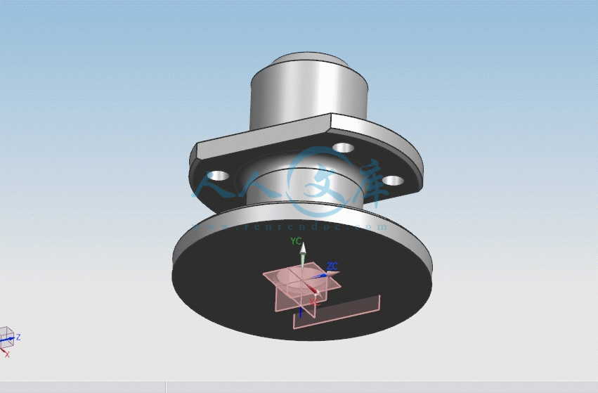
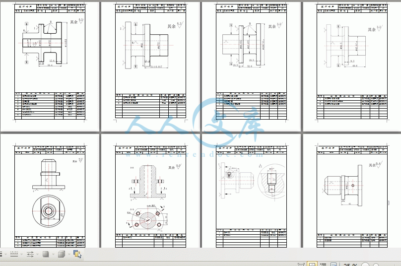
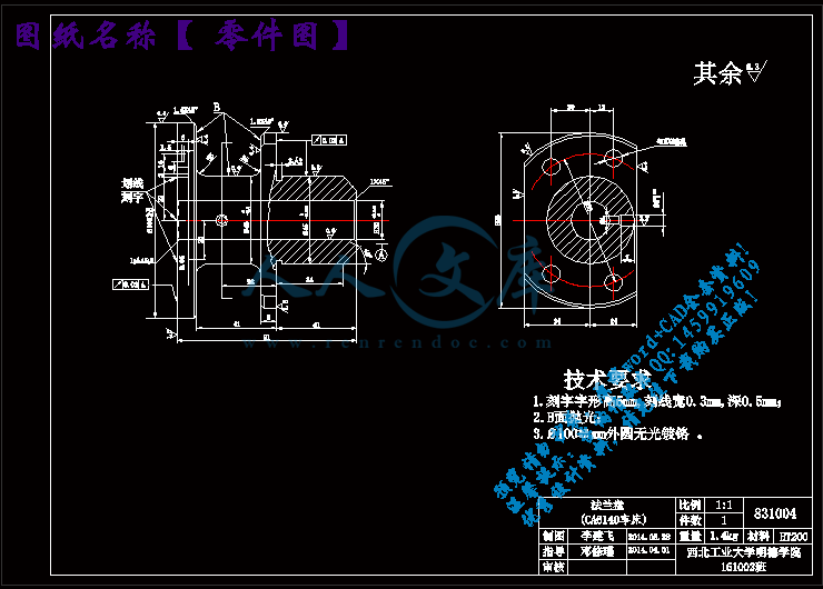
零件图.dwg
零件图.dwg

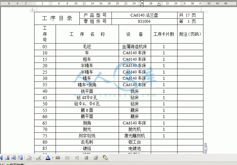
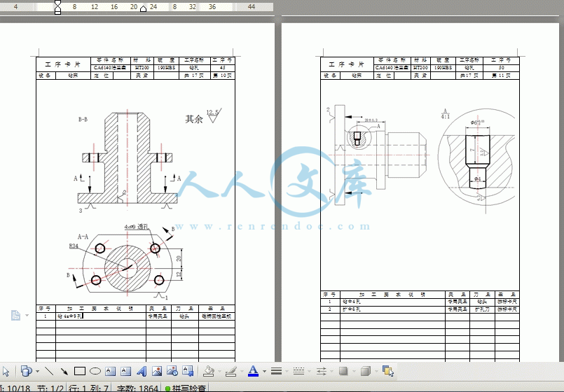
法兰盘831004加工工艺规程及钻4—φ9孔夹具设计【工艺装备+优秀+带UG三维图零件图+8张CAD图纸】【10FLP831004】

收藏

资源目录
跳过导航链接。
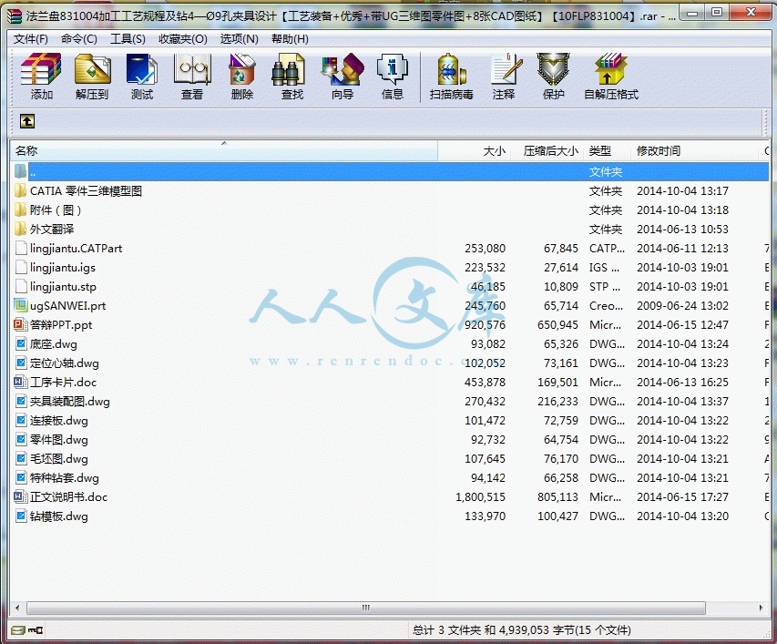
法兰盘831004加工工艺规程及钻4—φ9孔夹具设计【10FLP831004】.rar
零件图.dwg---(点击预览)
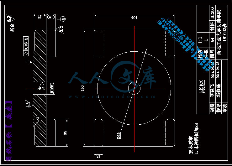
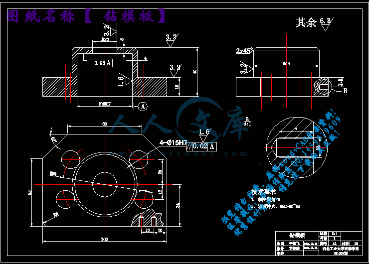
钻模板.dwg---(点击预览)
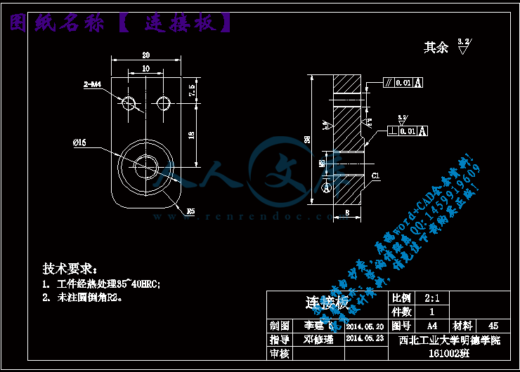
连接板.dwg---(点击预览)
答辩PPT.ppt---(点击预览)
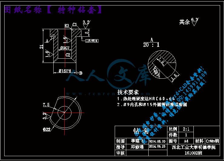
特种钻套.dwg---(点击预览)
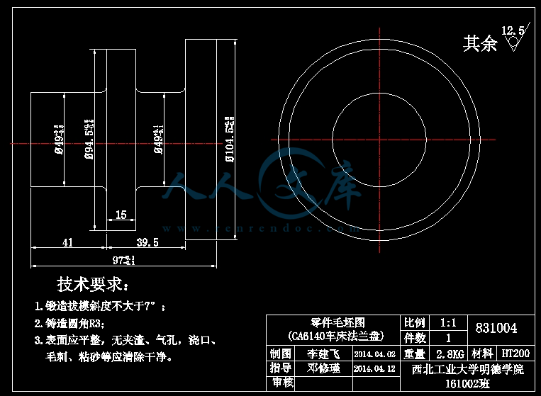
毛坯图.dwg---(点击预览)
正文说明书.doc---(点击预览)
底座.dwg---(点击预览)
工序卡片.doc---(点击预览)
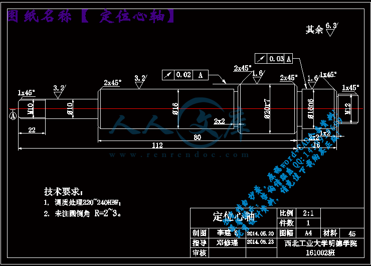
定位心轴.dwg---(点击预览)
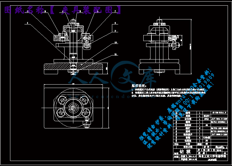
夹具装配图.dwg---(点击预览)
CATIA 零件三维模型图
dingweixiao.CATPart
dizuo.CATPart
KAIKOUDIANPIAN.CATPart
lianjieban.CATPart
lingjiantu.CATPart
luoding.CATPart
luoding2.CATPart
Product2.CATProduct
shaft.CATPart
shangmian luomu M8.CATPart
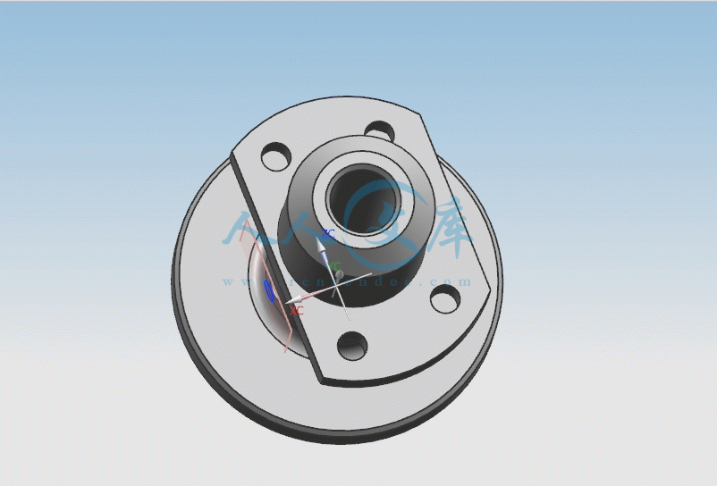
tezhongzuantao.CATPart
xiamian luomu M8.CATPart
youce luomu.CATPart
zuanmoban.CATPart
外文翻译
翻译封面.doc---(点击预览)
数控技术.doc---(点击预览)
NC Technology.pdf---(点击预览)
NC Technology.pdf.baiduyun.uploading.cfg
数控技术.doc.baiduyun.uploading.cfg
附件(图)
lingjiantu.CATPart
lingjiantu.igs
lingjiantu.stp
ugSANWEI.prt
压缩包内文档预览:
预览图
编号:342669    类型:共享资源    大小:4.88MB    格式:RAR    上传时间:2014-10-04 上传人:QQ14****9609 IP属地:陕西
20
积分
关 键 词:
法兰盘 拨叉 CA6140车床 车床拨叉 831004 机械加工 加工工艺 工艺规程 夹具设计 工艺装备
资源描述:

CA6140车床法兰盘的加工工艺规程及钻 4—Φ9孔钻床夹具设计

CA6140车床法兰盘钻 4—Φ9孔钻床夹具设计

CA6140车床法兰盘工艺规程及夹具设计

CA6140车床法兰盘831004加工工艺及钻φ6孔夹具设计

CA6140车床法兰盘831004加工工艺及钻φ6孔工艺装备设计

CA6140车床法兰盘831004钻φ6孔夹具设计

CA6140车床法兰盘831004加工工艺规程及车大法兰端面和ф20孔夹具设计

法兰盘零件的工艺规程及车大法兰端面和ф20孔工艺装备设计

CA6140车床法兰盘831004钻Φ4孔夹具设计

CA6140车床法兰盘加工工艺规程及夹具设计

CA6140车床法兰盘831004的机械加工工艺规程及铣Φ90上下两侧平面夹具设计

法兰盘的夹具设计

CA6140车床法兰盘(831004型号)的加工工艺规程及夹具设计

CA6140车床法兰盘(831004)零件的机械加工工艺规程及专用夹具设计

法兰盘831004加工工艺规程及钻4—?9孔夹具设计【工艺装备+优秀+带UG三维图零件图+8张CAD图纸】【10FLP831004】

【带任务书、答辩ppt、机械加工工艺过程、工序卡片全套】【word文档包含:42页@正文11700字】【详情如下】【需要咨询购买全套设计请加QQ1459919609】.bat

CATIA 零件三维模型图

lingjiantu.CATPart

lingjiantu.igs

lingjiantu.stp

ugSANWEI.prt

外文翻译

夹具装配图.dwg

定位心轴.dwg

工序卡片.doc

底座.dwg

正文说明书.doc

毛坯图.dwg

特种钻套.dwg

答辩PPT.ppt

连接板.dwg

钻模板.dwg

附件(图)

零件图.dwg

任务书

一、题目

   CA6140车床法兰盘的工艺规程和夹具设计

二、指导思想和目的要求

   毕业设计(论文)是培养学生自学能力、综合应用能力、独立工作能力的重要教学实践环节。

   在毕业设计中,学生应独立承担一部分比较完整的工程技术设计任务。要求学生发挥主观能动性,积极性和创造性,在毕业设计中着重培养独立工作能力和分析解决问题的能力,严谨踏实的工作作风,理论联系实际,以严谨认真的科学态度,进行有创造性的工作,认真、按时完成任务。

三、主要技术指标

1.   零件图一张;

2.   毛坯图一张;

3.   工艺规程一本;

4.   工艺装备(夹具1-2套);

5.   说明书一份

四、进度和要求

1.   分析并绘制零件图                     2周

2.   绘制毛坯图                           1周

3.   设计工艺路线及编制工艺规程           5周

4.   设计工艺装备                         4周

5.   编写说明书(论文)                   2周

五、主要参考书及参考资料

[1] 王先逵编著.机械制造工艺学[M].北京:清华大学出版社,1989

[2] 杨叔子.机械加工工艺师手册[M].北京:机械工业出版社,2001

[3] 朱耀祥,蒲林祥.现代夹具手册[M].北京:机械工业出版社,2010

摘 要

   本次毕业设计的题目是CA6140车床法兰盘的工艺规程和夹具设计,主要内容如下:

   首先,对零件进行分析,主要是零件作用的分析和工艺性分析,通过零件分析可以了解零件的基本情况,而工艺分析可以知道零件的加工表面和加工要求。根据零件图提出的加工要求,确定毛坯的制造形式和尺寸。

   其次,进行基面的选择,确定加工过程中的粗基准和精基准。根据选好的基准,制订工艺路线,通常制订两种以上的工艺路线,通过工艺方案的比较与分析,再选择可以使零件的几何形状、尺寸精度及位置精度等技术要求得到合理的保证的一种较佳工序路线。

   然后,根据已经选定的工序路线,确定每一步的切削用量及基本工时,并选择合适的机床和刀具和量具。

   最后,设计钻法兰盘4-?9孔的钻床夹具。设计钻床夹具,首先要仔细分析被加工零件的技术要求,运用夹具设计的基本原理和方法,拟定夹具设计方案;在满足加工精度的条件下,合理的进行安装、定位、夹紧;在完成夹具草图后,进一步考虑零件间的连接关系和螺钉、螺母、定位销等的固定方式,设计合理的结构实现各零部件间的相对运动;根据各零件的使用要求,选择相应的材料。

   完成钻床夹具的所有设计后,用AutoCAD进行二维图形的绘制,首先画装配图,然后从装配图上拆画零件图,标注相关尺寸及技术要求;再用CATIA画出三维模型图,最后进行论文的撰写、整理、修改完成该毕业设计。

关键词:  机械,法兰盘,加工工艺,夹具设计

ABSTRACT

   The subject of this graduation project is that CA6140 lathe ring flange processing technology rules and special-purpose jig of a certain process are designed, the main content is as follows:

   First of all, analyse , it is mainly analysis of the function of the part and craft analysis to the part , through part analyse can find out about basic situation of part, and craft analyse may know the processing surface of the part and is it require to process. The processing demand put forward according to the part picture, confirm the manufacture form. of the blank and sureness of the size.

   The second step, carry on the choice the base , confirm thick datum and precise datum in the processing course. According to the datum chosen , make the craft route , usually make the craft route of more than two kinds, with analysing through the comparison of the craft scheme, and then choosing be able to make such specification requirements as the precision of geometry form. size of the part and precision of position ,etc. get a kind of process of the rational assurance s.

   The third step, according to the already selected process route, confirm for every steps of cutting consumption and basic man-hour , choose suitable lathe and cutter. To rough machining , will check the power of the lathe .

   Finally , design the jig getting into the hole of the ring flange. Designed drilling fixture, the first careful analysis is the technical requirements for processing components, fixture design using the basic principles and methods.Prepared the fixture design scheme ;Meet the conditions of precision ,then reasonable installation, positioning, clamping;After the completion of draft fixture, and further consider the connection relation between parts and screws, nuts, pins and other fixed means,designing the reasonable structure to achieve relative motion between the various components;Requirements of the various components, select the appropriate materials.

   Completion of all drilling fixture design, using the AutoCAD drawing two-dimensional graphics,first draw assembly drawing, and then removed from the part drawing on the painting Parts,marking the related to size and technical requirements,finally, write a thesis, organize, edit, complete the graduation project.  

KEY WORDS:  machine, flange, process the craft, the tongs design

目  录

第1章  绪  论7

第2章  零件的结构工艺性分析8

   2.1 零件的作用8

   2.2 零件的工艺性分析8

第3章  工艺规程设计10

   3.1 确定毛坯的制造形式10

   3.2 基准的选择10

      3.2.1粗基准的选择10

      3.2.2精基准的选择11

   3.3 工艺路线的拟定11

      3.3.1 选择加工方法11

      3.3.2 划分加工阶段12

      3.3.3 安排加工顺序12

   3.4 机械加工余量、工序尺寸及毛坯尺寸的确定14

   3.5 确定切削用量及基本工时18

第4章  夹具设计与分析24

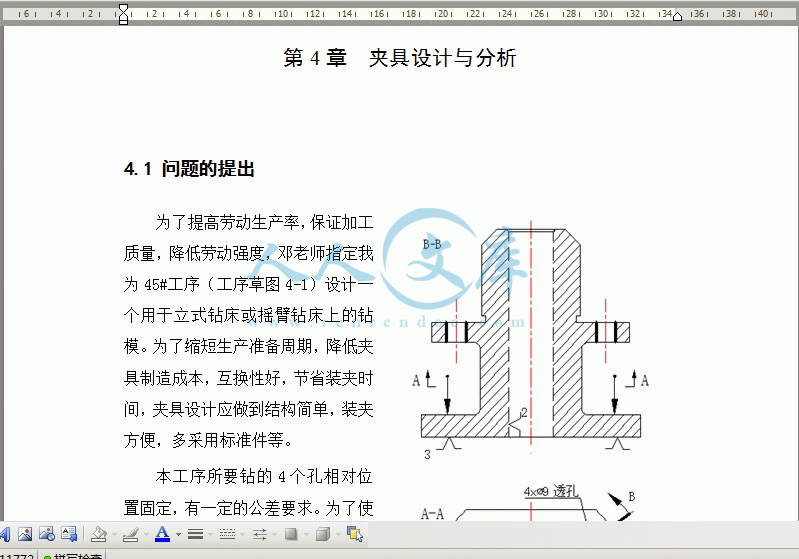
   4.1 问题的提出24

   4.2 夹具设计24

      4.2.1 夹具结构和类型的选取24

      4.2.2 夹具定位元件的选择26

      4.2.3 钻套的设计27

      4.2.4 钻模板设计28

      4.2.5 夹具体(底座)的设计29

      4.2.6 其他装置30

      4.2.7 夹紧装置的设计计算31

      4.2.8 切削力计算33

      4.2.9 机床夹具精度校核34

      4.2.10 绘制夹具总图37

      4.2.11 拆分夹具零件图37

第5章  全文总结39

参考文献40

致  谢41

毕业设计小结42

第1章  绪论

法兰盘类零件是在一个类似盘状的金属体的周边开上几个固定用的孔用于连接其它东西,此类零件在机械行业拥有非常重要的地位,其加工质量和精度直接影响一台机器的运作。因此,进行法兰盘类零件加工工艺的研究,对于整个机械行业而言,有着举足轻重的地位。

在提高工件加工质量的基础上同时提高生产效率是大部分机械零件工艺设计的准则,法兰盘类零件也是如此。一个合格的零件工艺规程,应该首先要求保证零件设计的尺寸和精度,其次要尽量合理地运用现有的工作条件,尽量减少辅助时间,提高生产效率。夹具的设计需要注意其精度对被加工工件精度的影响,务必确保使用夹具能够保证设计精度。本设计均以上述各原则为基准进行。

   由于专业知识有限,设计尚有许多不足之处,恳请各位老师、同学给予指出。

第2章  零件的结构工艺性分析

2.1 零件的作用

CA6140卧式车床上的法兰盘,为盘类零件,用于卧式车床上。车床的变速箱固定在主轴箱上,靠法兰盘定心。法兰盘内孔与主轴的中间轴承外圆相配,外圆与变速箱体孔相配,以保证主轴三个轴承孔同心,使齿轮正确啮合。主要作用是标明刻度,实现纵向进给。

参考文献

[1] 阎光明,侯忠滨,张云鹏.现代制造工艺基础.西安:西北工业大学出版社,2007

[2] 王先逵.机械加工工艺手册,北京:机械工业出版社,第二版,2003

[3] 邓文英.宋力宏.金属工艺学.北京:高等教育出版社,第五版,2008

[4] 吴  拓.简明机床夹具设计手册,北京:化学工业出版社,2010

[5] 陈宏钧.机械加工工艺设计员手册. 北京:机械工业出版社,2009

[6] 陈宏钧.实用机械加工工艺手册. 北京:机械工业出版社,2003

[7] 陈宏钧.金属切削工艺技术手册. 北京:机械工业出版社,2013.4

[8] 王权民.机床夹具设计,第1版,北京:科学出版社,2011

[9] 赵家齐.机械制造工艺学课程设计指导书,北京:机械工业出版社,1994

[10]卢秉恒.机械制造技术基础,第三版,西安:机械工业出版社,2007

[11]朱耀祥,蒲林祥.现代夹具设计手册.北京:机械工业出版社,2011

[12]钱云峰.殷锐,互换性与技术测量. 北京:电子工业出版社,2011.4

[13]李名望.机床夹具设计实例教程. 北京:化学工业出版社,2009

内容简介:
- 1 -NC Technology1、Research current situation of NC lathe in our timesResearch and development process to such various kinds of new technologies asnumerical control lathe , machining center , FMS , CIMS ,etc. of countries all over theworld, linked to with the international economic situation closely. The machine toolindustry has international economy to mutually promote and develop, enter 21 alerteras of World Affairs, the function that peoples knowledge plays is more outstanding ,and the machine tool industry is regarded as the foundation of the manufacturingindustry of the machine, its key position and strategic meaning are more obvious.Within 1991-1994 years, the economic recession of the world, expensive FMS, CIMSlowers the temperature, among 1995-2000 years, the international economy increasesat a low speed, according to requisition for NC lathe and the world four majorinternational lathes exhibition in order to boost productivity of users of various fieldsof present world market (EMO , IMTS , JIMTOF , China CIMT of Japan of U.S.A. ofEurope), have the analysis of the exhibit, there are the following several points mainlyin the technical research of NC lathe in our times:(1) 、Pay more attention to new technology and innovationWorldwide , are launching the new craft , new material , new structure , newunit , research and development of the new component in a more cost-effectivemanner, developmental research of for instance new cutter material , the new electricmain shaft of main shaft structure , high speed , high-speed straight line electricalmachinery ,etc. Regard innovating in improvement of the processing technology asthe foundation, for process ultra and hard difficult to cut material and specialcomposite and complicated part , irregular curved surface ,etc. research and developnew lathe variety constantly.(2) 、Improve the precision and research of machine toolingIn order to improve the machining accuracy of the machining center , are- 2 -improving rigidity of the lathe , reduction vibration constantly, dispel hotly and out ofshape, reduce the noise , improve the precision of localization of NC lathe , repeatprecision , working dependability , stability , precision keeping, world a lot of countrycarry on lathe hot error , lathe sport and load out of shape software of errorcompensate technical research, take precision compensate , software compensatemeasure improve , some may make this kind of error dispel 60% already. And isdeveloping retrofit constantly, nanometer is being processed.(3) 、Improve the research of the machine tooling productivityWorld NC lathe, machining center and corresponding some development ofmain shaft , electrical machinery of straight line , measuring system , NC system ofhigh speed, under the prerequisite of boosting productivity.(4) 、What a lot of countries have already begun to the numerical controlsystem melt intelligently, openly, study networkedlyA、elligent research of the numerical control systemMainly showing in the following aspects: It is intelligent in order to pursue theefficiency of processing and process quality, the self-adaptation to the processingcourse is controlled, the craft parameter produces research automatically; Join theconvenient one in order to improve the performance of urging and use intelligently, tothe feedback control , adaptive operation , discerning automatically load selectsmodels automatically , since carries on research whole definitely ,etc. of the electricalmachinery parameter; There are such research of the respect as intelligent automaticprogramming , intelligent man-machine interface , intelligence diagnosing , intelligentmonitoring ,etc.B、 The numerical control system melts and studies openMainly showing in the following aspects: The development of the numericalcontrol system is on unified operation platform, face the lathe producer and supportfinally, through changing, increasing or cutting out the structure target(numericalcontrol target ), form the seriation, and can use users specially conveniently and thetechnical know-how is integrated in the control system, realize the open numericalcontrol system of different variety , different grade fast, form leading brand products- 3 -with distinct distinction. System structure norm of the open numerical control systemat present, norm , disposing the norm , operation platform , numerical controlsystematic function storehouse and numerical control systematic function softwaredeveloping instrument ,etc. are the core of present research to pass through.C、Meeting the manufacture system of the production line , demand for theinformation integration of the manufacturing company networkedly greatly ofnumerical control equipment, it is a basic unit of realizing the new manufacture modetoo.2、Classification of the machining center(1)Process according to main shaft space position when it classifies to beas follows, horizontal and vertical machining center.Horizontal machining center, refer to the machining center that the axis level ofthe main shaft is set up . Horizontal machining center for 3-5 sport coordinate axis, acommon one three rectilinear motion coordinate axis and one turn the coordinate axisof sports round (turn the workingbench round), it can one is it is it finish other 4 Taxiprocessing besides installing surfaces and top surfaces to insert to install in work piece,most suitable for processing the case body work piece . Compared with strength typemachining center it, the structure is complicated, the floor space is large, quality islarge, the price is high.Vertical machining center, the axis of the main shaft of the vertical machiningcenter, in order to set up vertically, its structure is mostly the regular post type, theworkingbench is suitable for processing parts for the slippery one of cross, have 3rectilinear motion coordinate axis generally , can find a room for one horizontalnumerical control revolving stage (the 4th axle ) of axle process the spiral part atworkingbench. The vertical machining center is of simple structure, the floor space issmall, the price is low, after allocating various kinds of enclosures , can carry on theprocessing of most work pieces .Large-scale gantry machining center, the main shafts are mostly set up vertically,is especially used in the large-scale or with complicated form work piece , is it spendthe many coordinate gantry machining center to need like aviation , aerospace- 4 -industry , some processing of part of large-scale steam turbine.Five machining centers, this kind of machining center has function of thevertical and horizontal machining center, one is it after inserting , can finish all fiveTaxi processing besides installing the surface to install in work piece, the processingway can make form of work piece error lowest , save 2 times install and insertworking, thus improve production efficiency , reduce the process cost.(2)Classify by craft useIs it mill machining center to bore, is it mill for vertical door frame machiningcenter , horizontal door frame mill the machining center and Longmen door framemill the machining center to divide into. Processing technology its rely mainly on thefact that the door frame is milled, used in case body, shell and various kinds ofcomplicated part special curve and large processes , curved surface of outline process,suitable for many varieties to produce in batches small.Complex machining center, point five times and compound and process mainly,the main shaft head can be turned round automatically, stand, lie and process, after themain shaft is turned round automatically, realize knowing that varies in the horizontaland vertical direction.(3)Classify by special functionSingle workingbench , a pair of workingbench machining center;Single axle , dual axle , three axle can change machining center , main shaft ofcase;Transfer vertically to the tower machining center and transfer ;One hundred sheets of storehouses adds the main shaft and changes one onehundred sheets of machining centers;One hundred sheets of storehouses connects and writes hands to add the mainshaft and change one hundred sheets of machining centers;One hundred sheets of storehouses adds the manipulator and adds one pair ofmain shafts to transfer to the tower machining center.3、Development trend of the current numerical control latheAt present, the advanced manufacturing technology in the world is rising- 5 -constantly, such application of technology as ultrafast cutting , ultraprecisionprocessing ,etc., the rapid development of the flexible manufacturing system andintegrated system of the computer one is constant and ripe, have put forward higherdemand to the process technology of numerical control. Nowadays the numericalcontrol lathe is being developed in several following directions.(1). The speed and precision at a high speed , high accuracy are two importantindexes of the numerical control lathe , it concerns directly that processes efficiencyand product quality. At present, numerical control system adopt-figure number,frequency high processor, in order to raise basic operation speed of system.Meanwhile , adopt the super large-scale integrated circuit and many microprocessorsstructure, in order to improve systematic data processing ability , namely improve andinsert the speed and precision of mending operation. Adopt the straight line motor andurge the straight line of the lathe workingbench to be servo to enter to the way directly,it is quite superior that its responds the characteristic at a high speed and dynamically.Adopt feedforward control technology , make it lag behind error reduce greatly , thusimprove the machining accuracy cut in corner not to track.For meet ultrafast demand that process, numerical control lathe adopt mainshaft motor and lathe structure form that main shaft unite two into one, realizefrequency conversion motor and lathe main shaft integrate , bearing , main shaft ofelectrical machinery adopt magnetism float the bearing , liquid sound pigeonhole suchforms as the bearing or the ceramic rolling bearing ,etc. At present, ceramic cutterand diamond coating cutter have already begun to get application.( 2 ) . Multi-functional to is it change all kinds of machining centers oforganization (a of capacity of storehouse can up to 100 of the above ) automatically tofurnished with, can realize milling paring , boring and pares , bores such many kindsof processes as paring , turning , reaming , reaming , attacking whorl ,etc. to processat the same time on the same lathe , modern numerical control lathe adopt many mainshaft , polyhedron cut also , carry on different cutting of way process to one differentposition of part at the same time. The numerical control system has because adoptedmany CPU structure and cuts off the control method in grades, can work out part- 6 -processing and procedure at the same time on a lathe , realize so-called the frontdesk processes , the backstage supporter is an editor . In order to meet the needs ofintegrating the systematic one in flexible manufacturing system and computer,numerical control system have remote serial interface , can network , realize datacommunication , numerical control of lathe, can control many numerical controllathes directly too.(3). Intelligent modern numerical control lathe introduce the adaptive controltechnology, according to cutting the change of the condition, automatic workingparameter, make the processing course can keep the best working state , thus get thehigher machining accuracy and roughness of smaller surface , can improve the servicelife of the cutter and production efficiency of the equipment at the same time .Diagnose by oneself , repair the function by oneself, among the whole working state,the system is diagnosed, checked by oneself to CNC system and various kinds ofequipment linking to each other with it at any time. While breaking down , adopt themeasure of shutting down etc. immediately , carry on the fault alarm, brief onposition , reason to break down ,etc. Can also make trouble module person who takeoff automatically , put through reserve module , so as to ensure nobody demand ofworkingenvironment.For realize hightrouble diagnosethat requires,itsdevelopment trend adopts the artificial intelligence expert to diagnose the system.(4). Numerical control programming automation with the development ofapplication technology of the computer, CAD/CAM figure interactive automaticprogramming has already get more application at present, it is a new trend of thetechnical development of numerical control. It utilize part that CAD draw processpattern , is it calculate the trailing punishing to go on by cutter orbit data of computerand then, thus produce NC part and process the procedure automatically, in order torealize the integration of CAD and CAM. With the development of CIMS technology ,the full-automatic programming way in which CAD/CAPP/CAM integrates hasappeared again at present, it, and CAD/CAM systematic programming greatdifference their programming necessary processing technology parameter neednt byartificial to participate in most, get from CAPP database in system directly.- 7 -(5). The dependability of the dependability maximization numerical controllathe has been the major indicator that users cared about most all the time . Thenumerical control system will adopt the circuit chip of higher integrated level , willutilize the extensive or super large-scale special-purpose and composite integratedcircuit, in order to reduce the quantity of the components and parts , to improvedependability . Through the function software of the hardware, in order to meetvarious kinds of demands for controlling the function, adopt the module ,standardization , universalization and seriation of the structure lathe noumenonn ofthe hardware at the same time , make not only improve the production
温馨提示:
1: 本站所有资源如无特殊说明,都需要本地电脑安装OFFICE2007和PDF阅读器。图纸软件为CAD,CAXA,PROE,UG,SolidWorks等.压缩文件请下载最新的WinRAR软件解压。
2: 本站的文档不包含任何第三方提供的附件图纸等,如果需要附件,请联系上传者。文件的所有权益归上传用户所有。
3.本站RAR压缩包中若带图纸,网页内容里面会有图纸预览,若没有图纸预览就没有图纸。
4. 未经权益所有人同意不得将文件中的内容挪作商业或盈利用途。
5. 人人文库网仅提供信息存储空间,仅对用户上传内容的表现方式做保护处理,对用户上传分享的文档内容本身不做任何修改或编辑,并不能对任何下载内容负责。
6. 下载文件中如有侵权或不适当内容,请与我们联系,我们立即纠正。
7. 本站不保证下载资源的准确性、安全性和完整性, 同时也不承担用户因使用这些下载资源对自己和他人造成任何形式的伤害或损失。
提示  人人文库网所有资源均是用户自行上传分享,仅供网友学习交流,未经上传用户书面授权,请勿作他用。
关于本文
本文标题:法兰盘831004加工工艺规程及钻4—φ9孔夹具设计【工艺装备+优秀+带UG三维图零件图+8张CAD图纸】【10FLP831004】
链接地址:https://www.renrendoc.com/p-342669.html

官方联系方式

2:不支持迅雷下载,请使用浏览器下载   
3:不支持QQ浏览器下载,请用其他浏览器   
4:下载后的文档和图纸-无水印   
5:文档经过压缩,下载后原文更清晰   
关于我们 - 网站声明 - 网站地图 - 资源地图 - 友情链接 - 网站客服 - 联系我们

网站客服QQ:2881952447     

copyright@ 2020-2025  renrendoc.com 人人文库版权所有   联系电话:400-852-1180

备案号:蜀ICP备2022000484号-2       经营许可证: 川B2-20220663       公网安备川公网安备: 51019002004831号

本站为文档C2C交易模式,即用户上传的文档直接被用户下载,本站只是中间服务平台,本站所有文档下载所得的收益归上传人(含作者)所有。人人文库网仅提供信息存储空间,仅对用户上传内容的表现方式做保护处理,对上载内容本身不做任何修改或编辑。若文档所含内容侵犯了您的版权或隐私,请立即通知人人文库网,我们立即给予删除!