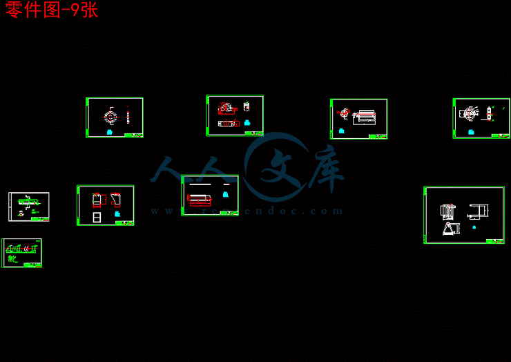
零件图-9张.dwg
零件图-9张.dwg

送料量调整输送装置设计及仿真[三维SW]【含全套10张CAD图纸】【答辩毕业资料】

收藏

资源目录
跳过导航链接。
送料量调整输送装置设计及仿真[三维SW]【含全套CAD图纸】【答辩毕业资料】.rar
零件图-9张.dwg---(点击预览)
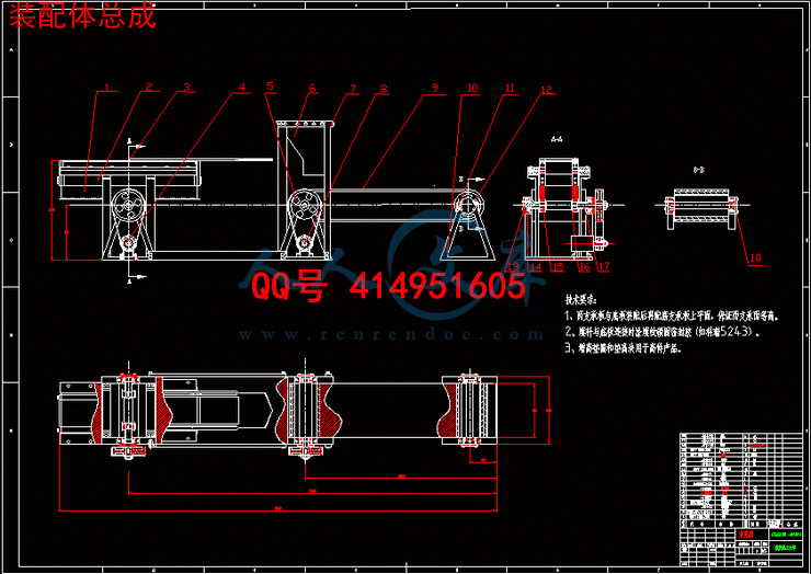
装配体总成.dwg---(点击预览)
毕业设计(论文)任务书.doc---(点击预览)
毕业设计论文.doc---(点击预览)
文献综述.doc---(点击预览)
开题报告.doc---(点击预览)
外文翻译.doc---(点击预览)
Y电动机型号大全.doc---(点击预览)
3D-SW
左部控制部分
控制支撑杆
挡板.SLDPRT
挡板架.SLDPRT
控制料斗杆1.SLDPRT
控制料斗杆2.SLDPRT
滑道盖.SLDPRT
齿条滑道.SLDPRT
齿条连杆.SLDPRT
大带轮键.SLDPRT
左连接杆.SLDPRT
控制上盖螺杆.SLDPRT
控制上轴盖.SLDPRT
控制垫片.SLDPRT
控制大带轮.SLDPRT
控制套筒.SLDPRT
控制小带轮.SLDPRT
控制螺杆.SLDPRT
控制轴.SLDPRT
控制轴承20.SLDPRT
控制轴承环.SLDPRT
控制轴端盖.SLDPRT
控制透轴盖.SLDPRT
控制键.SLDPRT
控制齿轮.SLDPRT
控制齿轮键.SLDPRT
皮带2.SLDPRT
直尺条.SLDPRT
直尺条(2).SLDPRT
装配.SLDASM
齿条装配.SLDASM
电机
基座垫片.SLDPRT
小带轮.SLDPRT
电机后端盖.SLDPRT
电机基座螺杆.SLDPRT
电机壳.SLDPRT
电机端盖.SLDPRT
电机螺杆.SLDPRT
电机装配.SLDASM
电机转子.SLDPRT
皮带.SLDPRT
键.SLDPRT
上轴盖.SLDPRT
传送带.SLDPRT
垫片1.SLDPRT
大带轮.SLDPRT
支架1.SLDPRT
支架上垫片.SLDPRT
支架上螺杆.SLDPRT
支架右.SLDPRT
支架左.SLDPRT
料斗.SLDPRT
料斗杆1.SLDPRT
料斗杆2.SLDPRT
料斗杆右.SLDPRT
滚筒1.SLDPRT
滚筒2.SLDPRT
电机装配.SLDASM
端盖1.SLDPRT
螺杆1.SLDPRT
螺杆2.SLDPRT
装配体1.SLDASM
装配体爆炸图.SLDASM
轴承20.SLDPRT
轴承环.SLDPRT
透端盖1.SLDPRT
键1.SLDPRT
三维图册
键.PNG---(点击预览)
透端盖.PNG---(点击预览)
装配体1.PNG---(点击预览)
装配体.PNG---(点击预览)
螺杆1.PNG---(点击预览)
端盖.PNG---(点击预览)
电机装配.PNG---(点击预览)
滚筒2.PNG---(点击预览)
滚筒1.PNG---(点击预览)
料斗杆右.PNG---(点击预览)
料斗杆1.PNG---(点击预览)
料斗杆.PNG---(点击预览)
料斗2.PNG---(点击预览)
料斗1.PNG---(点击预览)
料斗.PNG---(点击预览)
支架.PNG---(点击预览)
左支架.PNG---(点击预览)
大带轮.PNG---(点击预览)
垫片.PNG---(点击预览)
图片1_副本.jpg---(点击预览)
右支架.PNG---(点击预览)
传送带.PNG---(点击预览)
上轴盖.PNG---(点击预览)
左端控制部分
装配体仿真.avi
压缩包内文档预览:
预览图
编号:347018    类型:共享资源    大小:24.30MB    格式:RAR    上传时间:2014-10-23 上传人:好资料QQ****51605 IP属地:江苏
50
积分
关 键 词:
料量 调整 调剂 输送 装置 设计 仿真 三维 sw 全套 cad 图纸 答辩 毕业 资料
资源描述:

【温馨提示】 购买原稿文件请充值后自助下载。

[全部文件] 那张截图中的文件为本资料所有内容,下载后即可获得。


预览截图请勿抄袭,原稿文件完整清晰,无水印,可编辑。

有疑问可以咨询QQ:414951605或1304139763


    目     录

摘  要 ...............................................................Ⅰ

Abstract.............................................................Ⅱ

1 绪论..................................................................1
1.1 本课题研究的目的和意义 ...........................................1
1.2 本课题研究的内容..................................................2
 1.3 国内外研究情况及其发..............................................2

2 自动量调整带式输送机结构原理..........................................4
 2.1 自动量调整带式输送机工作原理......................................4
 2.2 自动量调整带式输送机主要结构......................................5
 2.3 自动量调整带式输送机装配及转换二维图.............................12

3 自动量调整带式输送机设计计算.........................................14
 3.1 已知原始数据及工作条件...........................................14
 3.2 挠性体摩擦传动原理...............................................15  
3.3 工作弧与静止弧...................................................16
3.4 驱动滚筒的摩擦牵引力.............................................17
3.5 主要零件尺寸计算.................................................18

4 自动量调整带式输送机驱动装置的设计与选用.............................21
 4.1 电动机种类及参数.................................................21
 4.2 三相电机正反转原理...............................................22
 4.3 电机1的选用.....................................................23
 4.4 电机2的选用.....................................................24                                  
 4.5 减速部分.........................................................25
5 自动带式输送机主要部件的设计与选用.......................... .. .....26
 5.1 输送带...........................................................26
 5.2 传动滚筒.........................................................27
 5.3 托辊.............................................................28
 5.4 支架.............................................................29
 5.5 拉紧装置.........................................................30

6 结论................................................................31致 谢.................................................................32参考献文..............................................................33
文献综述..............................................................34


                     摘    要

本次毕业设计是关于饲料自动量调整带式输送机的设计。首先对带式输送机作了简单的概述;接着分析了自动量调整带式输送机的原理及设计计算方法;然后根据这些设计准则与计算选型方法按照给定参数要求进行选型设计;接着对所选择的输送机各主要零部件进行了三维建模造型。自动量调整带式输送机由三个主要部件组成:传送带装置、料斗装置、控制量调整装置。最后简单的说明了输送机的安装与维护。目前,带式输送机正朝着长自动化、长距离,高速度,低摩擦的方向发展。在带式输送机的设计、制造以及应用方面,目前我国与国外先进水平相比仍有较大差距,国内在设计制造带式输送机过程中存在着很多不足。本次自动量调整带式输送机设计,代表了设计的一般过程, 对今后的选型设计工作有一定的参考价值。                        

关键词: 带式输送机    量调整   三维模型


Abstract

The design is a graduation project about the belt conveyor. At first, it is introduction about the belt conveyor. Next, it is the principles about choose component parts of belt conveyor. After that the belt conveyor abase on the principle is designed. Then, it is checking computations about main component parts. The ordinary belt conveyor consists of six main parts: Drive Unit, Jib or Delivery End, Tail Ender Return End. Intermediate Structure, Loop Take-Up and Belt. At last, it is explanation about fix and safeguard of the belt conveyor. Today, long distance, high speed, low friction is the direction of belt conveyor’s development. Air cushion belt conveyor is one of them. At present, we still fall far short of abroad advanced technology in design, manufacture and using. There are a lot of wastes in the design of belt conveyor.

Keywords:  the belt conveyor   Drive Unit   Three-dimensional modeling


内容简介:
Y电动机型号大全及铭牌的含义Y系列电动机是一般用途的全封闭自扇冷式鼠笼型三相异步电动机。安装尺寸和功率等级符合IEC标准,外壳防护等级为IP44,冷却方法为IC411,连续工作制(S1)。适用于驱动无特殊要求的机械设备,如机床、泵、风机、压缩机、搅拌机、运输机械、农业机械、食品机械等。 Y系列电动机效率高、节能、堵转转矩高、噪音低、振动小、运行安全可靠。Y80315电动机符合Y系列(IP44)三相异步电动机技术条件JB/T9616-1999。Y355电动机符合Y系列(IP44)三相异步电动机技术条件JB5274-91。Y80315电动机采用B级绝缘。Y355电动机采用F级绝缘。额定电压为380V,额定频率为50Hz。功率3kW及以下为Y接法;其它功率均为接法。电动机运行地点的海拔不超过1000m;环境空气温度随季节变化,但不超过40;最低环境空气温度为-15;最湿月月平均最高相对湿度为90%;同时该月月平均最低温度不高于25。 电动机有一个轴伸,按用户需要,可制成双轴伸,第二轴伸亦能传递额定功率,但只能用联轴器传动。 按用户需要,还可供应其他功率、电压、频率、湿热带型(TH)、防护等级等电动机。二、详细参数型 号额定功率 额定电流 转速 效率 功率因数 堵转转矩堵转电流最大转矩噪声振动速度 重量额定转矩额定电流额定转矩1级2级kWAr/min%COS倍倍倍dB(A)mm/skg同步转速 600r/min 10级Y315S-10451015906.02.082872.8838Y315M-105512359092.02.082872.8960Y315L2-10751645906.02.082872.81180Y355M1-109019159593.02.0964.51620Y355M2-101102305956.02.0964.51775Y355L1-101322755956.02.0964.51880重 庆 理 工 大 学文 献 翻 译送料量调整输送装置设计二级学院 重庆机械工程学院 班 级 109040205 学生姓名 吴讯杰 学 号 10904020521 译 文 要 求1、译文内容必须与课题(或专业)内容相关,并需注明详细出处。2、外文翻译译文不少于2000字;外文参考资料阅读量至少3篇(相当于10万外文字符以上)。3、译文原文(或复印件)应附在译文后备查。 译 文 评 阅导师评语(应根据学校“译文要求”,对学生外文翻译的准确性、翻译数量以及译文的文字表述情况等作具体的评价) 指导教师: 年 月 日送料量调整输送装置设计摘要: 一种高速车床自动送料杆,特指一种于送料杆的外筒内部,设有以固定座、顶撑组件及压缩块所组成的润滑液补充装置,可适时补充轴承或需要自动润滑补给的装置与设备所需的润滑液,以及心轴的外部套设复数个由吸振性良好、耐磨性佳且兼具高散热性能的材质所制成的吸震环,可有效承受与外部的车床部件的接触或摩擦,以防止产生噪音。 速车床自动送料杆 技术领域:本发明涉及高速车床自动送料杆,特指一种于送料杆的外筒内部,设有以固定座、顶撑组件及压缩块所组成的润滑液补充装置,可适时补充轴承或需要自动润滑补给的装置与设备所需的润滑液,以及心轴的外部套设复数个由吸振性良好、耐磨性佳且兼具高散热性能的材质所制成的吸震环,可有效承受与外部的车床部件的接触或摩擦。背景技术: 已有的高速车床自动送料杆,是采用预加润滑液的传统作法,在轴承所需要的润滑液补充方面,无法作到适时自动添加的功效,必须人工定期拆卸补充,无法满足效率上的要求;再加上,以传统金属所制成的吸震环,在耐磨度及吸振性上的表现不佳,容易磨损,减少使用寿命。 请参阅图8,为已有轴承与油封环配置剖视平面图,其中,送料杆(A)的外筒(A1)内部设有多个轴承(A11),在预加润滑液后以油封环(A12)密封以保留润滑液;但在主轴(A2)高速旋转下所产生的高压及高热,很容易造成润滑液的渗漏与散逸,故必须时常拆卸添加润滑液,费时费力。 请参阅图9,为已有心轴筒与吸震环结构剖视平面图,其中,送料杆(A)的外筒(A1)所连接的心轴筒(A3)的外部以定位销(A32)套设吸震环(A31),吸震环(A31)为传统金属所制成,耐磨度及吸振性表现均不佳,容易磨损,使用寿命较短,并,已有心轴筒(A3)为多段式连接,强度不足,且,由于心轴筒(A3)的长度较长,而使拼接的心轴筒(A3)容易一段一段向下偏移,导致轴心无法保持水平状态,使后端送料杆(A)跟着偏移,而无法正确与车床保持同心确保车床加工零件的精密度,并使其枢转不顺畅而容易晃动,更会因此而产生噪音,故而损伤车床主机。 故前述所提及已有高速车床自动送料杆,尽管能够达成基本要求,但在润滑油不易保持及吸震环的耐磨度与吸振性上皆有所不足的情况下,无法发挥应有的功能及效率。 由于已有的高速车床自动送料杆,存在上述的缺失与不足,基于产业进步的未来趋势前提下,实在有必要提出具体的改善方案,以符合产业进步的所需,更进一步提供业界更多的技术性选择。发明内容: 本发明的目的在于解决已有高速车床自动送料杆在润滑液自动补充及吸震环耐用度方面不足等缺点,以及在实用化技术等方面受到限制的问题,一方面为达成改善润滑液添加自动化的目的,另一方面在于提升高速车床的产能及机台利用率,以达成高速车床自动送料杆所应具备的基本功能,使其兼具省时、维护简单及便利的要求。为了达成上述目的,其具体实行的技术手段及方案包括: 一种高速车床自动送料杆,系包含有扶料筒、外筒及主轴,其中:扶料筒,其系为一中空圆筒状体,设置于送料杆的前段,用以套装材料;外筒,其系为一中空圆筒状体,设置于送料杆的中段,该外筒的内部中段设有挡垣而形成第一容室及第二容室,并于第一容室依序组设有固定座、顶撑组件、压缩块,而第二容室依序组设有挡盘、复数个轴承及油塞环,其轴承及油塞环系交错置入;主轴,系穿设于复数个轴承内,该主轴的一端与扶料筒相连接。上述的压缩块与挡盘间的外筒内部空间以及轴承间的油塞环空间,均布满润滑液。上述的压缩块的侧边凹槽内组设一油封环。上述的外筒的挡垣设有穿孔,贯穿第一容室及第二容室,并于第二容室内壁上,设有一螺旋形的微线状凹槽。上述的顶撑组件系为弹性单元。上述的弹性单元系为弹簧。上述的顶撑组件系为压缩氮气。上述的送料杆的后段设有一体抽拉成型的心轴,该心轴与外筒作连接,心轴的外部套设复数个中空圆筒状的吸震环,而吸震环的材料为铁氟龙或非金属材料。上述的油塞环系分为第一油塞环、第二油塞环,第一油塞环的长度长于第二油塞环。上述该第二容器组设的复数个轴承的设置方式系以近扶料筒一侧的数量较远离一端多,且各轴承间以油塞环区隔。本发明的优点在于: 1.外筒内部设有以固定座、顶撑组件及压缩块所组成的润滑液补充装置,可适时补充轴承所需的润滑液。 2.外筒内部的轴承间设有油塞环,可长时间保持轴承的润滑液,减少散逸,以增进润滑及散热效能。 3.外筒的中空内壁上所设的具有螺旋形的微线状凹槽,提供润滑液补充装置内的润滑液渗入轴承间所需的流路。 4.心轴系为一体抽拉成型,支撑力及强度佳。 5.心轴的外部套设复数个中空圆筒状的吸震环,该吸震环采用吸振性良好、耐磨性佳且兼具高散热性能的材质所制成,如铁氟龙(Teflon)等,可有效承受与外部的车床部件的接触或摩擦,以防止产生噪音,及确保加工零件的精密度。 6.具有自动补充润滑液的润滑液补充装置,可减少人工拆卸补充润滑液的次数,以节省时间,增进高速车床的产能。 7.本发明不仅适用于高速车床,亦可适用于各类需再补充润滑液的加工机具。附图说明:图1:本发明第一实施例整体构造剖视图(一); 图1图2:本发明第一实施例整体构造剖视图(二); 图2 图3:本发明第二实施例整体构造剖视图; 图3图4:本发明心轴与吸震环结构剖视图; 图4图5:本发明第三实施例整体构造剖视图; 图5图6:本发明第四实施例整体构造剖视图; 图6图7:本发明的顶撑组件为压缩氮气的示意图; 图7图8:已有轴承与油封环配置剖视图;图8图9:已有心轴筒与吸震环结构剖视图。 图9【主要组件符号说明】(1)送料杆 (11)扶料筒 (12)外筒(121)容室 (1211)挡垣 (1212)穿孔(1213)螺纹接头 (1214)漏斗杯体 (122)第一容室(123)第二容室 (1231)微线状凹槽 (124)固定座(125)(125A)顶撑组件 (126)压缩块 (1261)凹槽(1262)油封环 (127)挡盘 (128)轴承(129)油塞环 (129A)第一油塞环 (129B)第二油塞环(13)主轴 (14)心轴 (141)吸震环(2)润滑液 (3)材料(A)送料杆 (A1)外筒(A11)轴承 (A12)油封环(A2)主轴 (A3)心轴筒(A31)吸震环 (A32)定位销具体实施方式: 请参阅图1、2,分别为本发明第一实施例整体构造剖视平面图(一)及本发明第一实施例整体构造剖视平面图(二),本发明为有送料杆(1),而送料杆(1)系包括有扶料筒(11)、外筒(12)及主轴(13),其中:扶料筒(11),其系为一中空圆筒状体,设置于送料杆(1)的前段,用以套装材料。外筒(12),其系为一中空圆筒状体,设置于送料杆(1)的中段,该外筒(12)的内部中段设有挡垣(1211)而形成第一容室(122)及第二容室(123),并于第一容室(122)依序组设有固定座(124)、顶撑组件(125)、压缩块(126),而第二容室(123)依序组设有挡盘(127)、复数个轴承(128)及油塞环(129),其轴承(128)及油塞环(129)系交错置入,该油塞环(129)系可分设成第一油塞环(129A)及第二油塞环(129B),第一油塞环(129A)的长度系长于第二油塞环(129B),组装后轴承(128)形成前二后一,其作用为提高送料杆(1)的支撑力,以避免送料杆(1)的一端下垂。主轴(13),系穿设于复数个轴承(128)内,该主轴(13)的一端与扶料筒(11)相连接。送料杆(1)的后段设有一心轴(14)另请先行参阅图4,该心轴(14)与外筒(12)作连接,心轴(14)的外部套设复数个中空圆筒状的吸震环(141)。实施时,压缩块(126)与挡盘(127)间的外筒(12)内部空间以及轴承(128)间的油塞环(129)空间,均布满润滑液(2);而油塞环(129)的功能在于可提供轴承充足的润滑液(2),以增进主轴(13)的润滑及散热效能,以提高零件的使用寿命,并降低更替零件或补充润滑液(2)的频率,进而提高使用效率;另,压缩块(126)的侧边凹槽(1261)内组设一油封环(1262),以防止润滑液(2)渗漏。当截面为六角形的材料(3)置于扶料筒(11)内,送料杆(1)由车床尾座端向夹头端推进而至夹持完成时,材料(3)会抵紧于扶料筒(11)的内部,随着夹头带动材料(3)的旋转,一端与扶料筒(11)相连接的主轴(13)也随之旋转,主轴(13)所穿设的复数个轴承(128)因高速旋转及承受轴向推力时,会产生高热,使润滑液(2)的黏度值下降,因而容易产生高温汽化等现象,导致润滑液(2)产生质变。图1上方所示压缩块(126)与挡盘(127)间的外筒(12)内部空间,充满足量的润滑液(2),而润滑液(2)的推挤传送是由固定座(124)上的顶撑组件(125)及顶撑组件(125)所连接的压缩块(126)两者所产生的弹性压紧力来达成;亦即当轴承(128)间的油塞环(129)空间内的润滑液(2)散逸时,会由挡盘(127)渗透,以补充润滑液(2)至轴承(128)上,直到压缩块(126)与挡盘(127)间的润滑液(2)即将耗尽或全数用毕时,再予以拆卸装填新的润滑液(2)。图2上方所示压缩块(126)与挡盘(127)间的外筒(12)内部空间的润滑液(2)的量,已较图1中少,代表由顶撑组件(125)及压缩块(126)将润滑液(2)推挤送至轴承(128)上的可观测变化,但轴承(128)上的润滑液(2)总是能维持一定的量,以确保轴承(128)的功效。 请参阅图3,为本发明第二实施例整体构造剖视平面图,其中,外筒(12)的挡垣(1211)设有穿孔(1212)以贯穿第一容室(122)及第二容室(123),并于第二容室(123)内壁上,设有一螺旋形的微线状凹槽(1231)。压缩块(126)与挡盘(127)间的外筒(12)内部空间,充满足量的润滑液(2),而润滑液(2)的推挤传送是由固定座(124)上的顶撑组件(125)及顶撑组件(125)所连接的压缩块(126)两者所产生的弹性压紧力来达成;亦即当轴承(128)间的油塞环(129)空间内的润滑液(2)散逸时,会由挡盘(127)渗透,经由外筒(12)中空内壁上的螺旋形的微线状凹槽(1231)来补充润滑液(2)至轴承(128)上,直到压缩块(126)与挡盘(127)间的润滑液(2)即将耗尽或全数用毕时,再予以拆卸装填新的润滑液(2)。 请参阅图4,为本发明心轴与吸震环结构剖视平面图,其中,送料杆(1)的后段设有一心轴(14),该心轴(14)与外筒(12)请参阅图1作连接,心轴(14)的外部套设复数个中空圆筒状的吸震环(141)。吸震环(141)系采用吸振性良好、耐磨性佳且兼具高散热性能的材质所制成,如铁氟龙(Teflon)或其它耐磨性佳的非金属材料等,可有效承受与外部的车床部件的接触或摩擦,以防止产生噪音,并可增加心轴(14)及吸震环(141)甚至是整个送料杆(1)的耐用寿命。 请参阅图5,为本发明第三实施例整体构造剖视平面图,其中,外筒(12)可为独立的单一结构体,其系为一中空圆筒状体,该外筒(12)的内部设有一具挡垣(1211)的容室(121),并于该容室(121)依序组设有压缩块(126)、顶撑组件(125)并锁合一固定座(124),压缩块(126)的侧边凹槽(1261)内组设一油封环(1262),以防止润滑液(2)渗漏;外筒(12)具挡垣(1211)的一端设有一螺纹接头(1213),该螺纹接头(1213)可与多种形式的扩充组件、装置或设备等连接,前述图1至图3的实施例,仅为应用于高速车床自动送料杆的其一连接型式;举凡需要自动润滑液供给的装置与设备,均可应用本独立的外筒(12)结构体作适当的配置。外筒(12)自动供液的原理系藉由固定座(124)前端的顶撑组件(125)推挤压缩块(126)所造成对容室(121)内的润滑液(2)的作用力,以保持足以自动供液的液静压力,以自动将润滑液(2)注入所需润滑的装置与设备等。 请参阅图6,为本发明第四实施例整体构造剖视平面图,其中,前述第三实施例中所提及独立的单一结构体的外筒(12),其外筒(12)具挡垣(1211)的一端亦可为一设有螺纹接头(1213)的锥形漏斗杯体(1214),该外筒(12)系为一中空圆筒状体,且外筒(12)的内部设有一容室(121),并于该容室(121)依序组设有压缩块(126)、顶撑组件(125)并锁合一固定座(124),压缩块(126)的侧边凹槽(1261)内组设一油封环(1262),以防止润滑液(2)渗漏;另外,螺纹接头(1213)则可与多种型式的扩充组件、装置或设备等连接,前述图1至图3的实施例,仅为应用于高速车床自动送料杆的其一连接型式;举凡需要自动润滑液供给的装置与设备,均可应用本独立的外筒(12)结构体作适当的配置。外筒(12)自动供液的原理与前述实施例者相同,亦即藉由固定座(124)前端的顶撑组件(125)推挤压缩块(126)所造成对容室(121)内的润滑液(2)的作用力,以保持足以自动供液的液静压力,以自动将润滑液(2)注入所需润滑的装置与设备等。 上述各实施例的顶撑组件(125)系可为弹性单元或压缩氮气,各图式中系为弹性单元弹簧,请参阅图7,其顶撑组件(125A)系为充填压缩氮气,藉由压缩氮气的受压力时可相对压缩体积,而当压力递减时其体积则会逐渐回复,使其如同受压迫的弹性单元一样具有顶撑压缩块(126)的作用。 改良与设计 综合上述,本发明系针对高速车床自动送料杆的应用技术,特指一种于送料杆的外筒内部,设有以固定座、顶撑组件及压缩块所组成的润滑液补充装置,可适时补充轴承或需要自动润滑补给的装置与设备所需的润滑液,以及心轴的外部套设复数个由吸振性良好、耐磨性佳且兼具高散热性能的材质所制成的吸震环,可有效承受与外部的车床部件的接触或摩擦,以提升相关组件的寿命,作一最佳的改良与设计,为本发明对于高速车床自动送料杆所作最具体的改良。原文:Automatic feeding pole of high speed lathe View Chinese Patent dataApplication Number: 200810009813 Application Date: 2008/2/4Abstract:The invention provides a high-speed lathe automatic material feeding rod, in particular to a lubricant supplementation device which is arranged inside the external cylinder of the material feeding rod and provided with a fixed seat, a top supporting component and a compression block and can duly supplement the lubricant which is required by a bearing or a device and an equipment which requires anautomatic lubrication supply, and a plurality of damping rings which are sleeved on the external part of a core shaft and made of the material with good damping performance, good wearability and highheat dissipation performance; the damping rings can effectively bear the contact or friction with external lathe parts and prevent the generation of noise.Bibliographic DataApplicant(s):Fang SonglingCountry/Province Code: 71 Main IPC:B23B 13/08IPC:B23B 13/08B23Q 11/12B23B 13/00B23B 13/12Publication Number:101224503Publication Date:080723Grant Number:101224503Grant Date:2010/9/29 INVENTOR(s):Fang SonglingAGENCY:35209 AGENT:fang huichun huang guoqiangAutomatic feeding area bar technique of high speed lathe:The invention relates to an automatic feeding rod speed lathe, in particular to a in the outer cylinder internal feeding rod, is provided with a fixed seat, supporting component and compression lubricating fluid block consisting of supplementary device, can be timely to add bearing or device and equipment need automatic lubrication replenishment lubricating fluid is required, and the external set a plurality of suction ring made of good vibration absorber, good abrasion resistance and high heat dissipation performance material, lathe parts can effectively bear and eThe technical background:Automatic feeding rod speed lathe has, is traditionally the pre lubricants, lubricating fluid required in bearing supplement, can not be timely and automatically add the effect of artificial periodic removal, must supplement, cannot satisfy the efficiency requirements; plus, the suction ring made of traditional metal, easy wear in the degree of wear and vibration of the poor performance, service life, reduce.Please refer to figure 8, as the plan, the bearing and oil seal ring configuration section, the feeding rod ( A ) of the outer cylinder ( A1 ) internal is provided with a plurality of bearing (A11), ring to seal in the lubricating fluid (A12 ) seal to retain lubricant; but in the spindle ( A2 ) high speed rotation produced high and high students, very easy to cause the leakage and dissipation of lubricating fluid, so must often remove add lubricating fluid, time-consuming and laborious.Please see Figure 9, for the axis cylinder and the suction ring structure section plane, wherein, the feeding rod ( A ) of the outer cylinder ( A1 ) mandrel tube connected (A3 ) external to the positioning pin ( A32 ) sets the suction ring (A31 ), shock-absorbing ring (A31). As the traditional metal, abrasion resistance and vibration resistance performance is not good, easy to wear, short service life, and has a mandrel, tube (A3) connection, is a multiple segment type strength is insufficient, and, because the mandrel tube ( A3 ) length is longer, the mandrel tube assembly (A3 ) to a section a downward shift in the axis, cannot maintain the level of the state, the back end of the feeding rod ( A ) with offset, and can not correctly and maintain concentric ensure lathe lathe precision, and the pivot is not smooth and easy to shake, more will therefore produce noise, so the damage of lathe machine.Therefore, the aforementioned automatic feeding rod has high speed lathe, although able to reach a basic requirement, but in the lubricating oil is not easy to keep and shock-absorbing ring wear resistance and vibration resistance would be inadequate, unable to play due function and efficiency.Because of the automatic feeding rod speed lathe already, the existence of the above deficiencies and shortcomings, based on the future trend of industrial progress under the premise, it is necessary to put forward concrete improvement scheme, in order to meet the industrial progress required, further to provide the industry technical more choice.The content of the invention:The aim of the invention is to solve the existing high-speed lathe automatic feeding rod is automatically added and suction shortcoming Zhenhuan durability deficiency in the lubricant, and the problem of restrictions in the practical technology, hand to improve the lubricating liquid adding automation purposes, on the other hand, is to improve the utilization of capacity and high-speed lathe machine the basic functions, to achieve high speed lathe automatic feeding rod should possess, which has time saving, easy maintenance and convenient requirements.To achieve the above purpose, including technical means and plan the implementation:Automatic feeding rod of a high-speed lathe, line contains a rotary cylinder, outer cylinder and shaft, wherein the rotary cylinder:, which is a hollow cylindrical body, is arranged in the feeding rod of the preceding paragraph, to suit materials; outer cylinder, which is a hollow cylindrical body, is arranged to send the middle rod, the outer cylinder is arranged in the middle section of the retaining wall and the formation of the first chamber and the two chamber, and the chamber are sequentially with fixed seat, supporting assembly, compression block to the first, and the second chamber is provided with a baffle plate are sequentially, a plurality of bearing and oil ring, the bearing and the oil ring lines staggered placement; spindle, arranged in a plurality of bearing, one end of the spindle and the rotary cylinder is connected.The compression block and the block inside the outer cylinder space disc and bearing oil ring space, are filled with lubricating liquid.Compression block side grooves in the group with an oil seal ring.The retaining wall of the outer cylinder is provided with a perforation, through the first chamber and the two chamber, and the chamber wall in second, with a spiral line-shaped groove.The top supporting component for elastic element.The elastic element such as spring.The top supporting component is compressed nitrogen.Feeding rod above the rear section is integrally drawing molding mandrel, the mandrel and the outer cylinder are connected, the external set with a plurality of hollow cylindrical suction ring, and shock-absorbing ring material is PTFE or non-metallic materials.The oil plug ring system is divided into a first oil ring, second ring, the first oil ring length longer than second oil ring.Setting the second container group provided with a plurality of bearing number nearly rotary barrel side is far away from the end, and each bearing with oil ring segments.xternal contact or friction.The invention has the advantages of:The 1 outer barrel is provided with a fixed seat, supporting component and compression lubricating fluid block consisting of supplementary device, can be timely to add lubricant required for bearings.Oil ring bearing is arranged between 2 inside the outer cylinder can be kept for a long time, lubricants, bearings reduce dissipation, in order to enhance the efficiency of lubrication and cooling.The hollow inner wall of outer cylinder with 3 on the micro linear spiral grooves, lubricating fluid flow path required lubricant into the bearing between the supplementary device.4 spindle system as a whole drawing forming, the supporting force and strength.5 the external set a plurality of hollow cylindrical shock-absorbing ring, the suction ring made by a good vibration absorber, good abrasion resistance and high heat dissipation material, such as Teflon ( Teflon ), lathe parts can effectively bear and external contact or friction, to prevent noise, and ensure the precision machining parts.6 with lubricating liquid automatic supply of lubricating fluid supply device, furnace can reduce manual disassembly added lubricating fluid, to save time, enhance the capacity of high speed lathe.7 the invention is not only suitable for high speed lathe processing equipment, can also be used in all kinds of need to add the lubricating liquid.Description of figures:The specific implementation way:Please see Figure 1, 2, respectively, a first embodiment of the present invention structure section plane graph ( a ) and a first embodiment of the present invention structure section plane ( two ), the invention is a feeding rod ( 1 ), and the feeding rod ( 1 ) comprises a rotary cylinder ( 11 ), the outer cylinder ( 12 ) and ( 13 ), wherein the spindle:Rotary cylinder ( 11 ), which is a hollow cylindrical body, is arranged in the feeding rod ( 1 ) of the preceding paragraph, to suit materials.The outer cylinder ( 12 ), which is a hollow cylindrical body, is arranged in the feeding rod ( 1 ) in the middle, the outer cylinder (12 ) is arranged in the middle section of the inner retaining wall ( 1211 ) and the formation of the first chamber and the two chamber ( 122 ) (123 ), and the chamber on the first ( 122 ) sequentially with fixed seat ( 124 ), the top supporting component (125 ), compression block (126), and the second chamber ( 123 ) sequentially with the retaining plate (127 ), a plurality of bearing ( 128 ) and the oil ring (129 ), the bearing (128 ) and the oil piston ring ( 129 ) lines staggered placement, the oil ring ( 129 ) can be divided into the first oil ring ( 129A ) and two oil ring (129B), the first oil ring ( 129A ) the length is longer than second oil ring ( 129B ), assembled bearing (128 ) formed after the first two a the role, to improve the feed rod ( 1 ) supporting force, in order to avoid feeding rod ( 1 ) is sagging.Spindle (13 ), arranged in a plurality of bearing ( 128 ), the main shaft (13 ) is connected with the rotary cylinder ( 11 ) is connected.Feeding rod ( 1 ) of the rear section is provided with a spindle ( 14 ) ( see Figure 4 ) please in advance, the mandrel ( 14 ) and the outer cylinder ( 12 ) are connected, the mandrel (14 ) of the external sleeve is provided with a plurality of hollow cylindrical shock-absorbing ring ( 141 ).When implemented, compression block ( 126 ) with the retaining plate ( 127 ) between the outer cylinder ( 12 ) and ( 128 ) bearing the internal space between the oil ring ( 129 ) space, is full of lubricant ( 2 ); and the oil ring ( 129 ) function is to provide sufficient lubrication ( bearing 2 ), to promote the main shaft ( 13 ) lubrication and heat dissipation efficiency, in order to improve the service life of parts, and reduce the replacement parts or added lubricant ( 2 ) frequency, and improve the efficiency of the use of; on the other, compression block ( 126 ) of the side groove ( 1261 ) in the group with an oil seal ring ( 1262 ), to prevent fluid leakage ( 2 ).When the section is hexagonal materials (3 ) arranged in the rotary cylinder ( 11 ), feeding rod ( 1 ) by the lathe tail block end to end to complete the push clamping chuck, material (3 ) will be tightly on the rotary cylinder ( 11 ) inside, with chuck drive material (3 ). Rotary, rotary cylinder with one end of the spindle ( 11 ) connected to the (13 ) along with the rotation of the spindle ( 13 ), a plurality of bearing wear set (128 ) because of high rotation speed and axial thrust, can produce high fever, make the lubricating fluid ( 2 ) viscosity decreased, so easy to produce high-temperature vaporization such phenomena, resulting in lubricant ( 2 ) have the qualitative change.Figure 1 above shows the compression block ( 126 ) with the retaining plate ( 127 ) between the outer cylinder ( 12 ) internal space, lubricating fluid filled with enough ( 2 ), and the lubricating fluid ( 2 ) push conveyor is composed of a fixed seat ( 124 ) top supporting component (125 ) and the supporting component ( 125 ) the compression block connection ( 126) elastic pressing force generated by the two to reach; that is when the bearing ( 128 ) between the oil ring ( 129 ) lubricating fluid space (2 ) escape, by retaining plate ( 127 ) permeability, to supplement the lubricating fluid ( 2 ) to the bearing ( 128 ), until the compression block ( 126 ) with the retaining plate ( 127 ) lubricating fluid between (2 ) is about to run out or full use of Bi, then give the dismantling fill lubricant new ( 2 ).Figure 2 above shows the compression block ( 126 ) with the retaining plate ( 127 ) between the outer cylinder ( 12 ) lubricating fluid interior space ( 2 ) of the quantity is less, in Figure 1, represented by the top supporting component ( 125 ) and a compression block ( 126 ) the lubricant (2) push to bearing ( 128 ) observable change, but bearing ( 128 ) lubricant on the (2 ) can always maintain a certain amount, to ensure that the bearing ( 128 ).Please refer to figure 3, as the plan, as the embodiment of overall structure of the second section, the outer cylinder ( 12 ) retaining wall (1211 ) is provided with a perforation ( 1212 ) through the first chamber ( 122 ) and a two containing chamber (123 ), and the chamber in second (123 ) on the inner wall, with micro linear groove is a spiral ( 1231 ).Compression block ( 126 ) with the retaining plate ( 127 ) between the outer cylinder ( 12 ) internal space, lubricating fluid filled with enough ( 2 ), and the lubricating fluid ( 2 ) push conveyor is composed of a fixed seat ( 124 ) top supporting component (125 ) and the supporting component (125 ) of the compressed block ( 126 ) connected to the elastic pressing force generated by the two to reach; that is when the bearing ( 128 ) between the oil ring ( 129 ) lubricating fluid space (2 ) escape, by retaining plate (127 ) via osmotic, outer cylinder ( 12 ) micro linear groove on the inner wall spiral hollow shape the ( 1231 ) to add lubricant to the bearing ( 2 ) ( 128 ), until the compression block (126) with the retaining plate ( 127 ) lubricating fluid between (2 ) is about to run out or full use of Bi, then give the dismantling fill lubricant new ( 2 ).Please refer to figure 4, the mandrel and the suction ring structure section plane, wherein, the feeding rod ( 1 ) of the rear section is provided with a spindle ( 14 ), the mandrel ( 14 ) and the outer cylinder ( 12 ) ( see Figure 1 ) for the connection, the mandrel ( 14 ) of the external sleeve. A plurality of hollow cylindrical shock-absorbing ring ( 141 ).Shock-absorbing ring ( 141 ) with good vibration absorber, good abrasion resistance and high heat dissipation performance material produced, such as Teflon ( Teflon ) or other good abrasion resistance of non-metallic materials, lathe parts can effectively bear and external contact or friction, to prevent noise, and can increase the mandrel ( 14 ) and shock-absorbing ring (141 ) and even the whole feeding rod ( 1 ) of the durable life.Please refer to figure 5, as the plan, as the embodiment of overall structure of the third section, the outer cylinder ( 12 ) can be a single structure independent of the body, which is a hollow cylindrical body, the outer cylinder ( 12 ) is internally provided with a retaining wall ( 1211 ) chamber ( 121 ) in the chamber, and (121 ) are sequentially provided with compressed block ( 126 ), the top supporting component (125 ) and locking a fixed seat ( 124 ), compression block ( 126 ) of the side groove ( 1261 ) in the group with an oil seal ring ( 1262 ), to prevent the lubricating fluid ( 2 ) leakage; the outer cylinder ( 12 ) with the retaining wall ( 1211 ) is provided with a threaded joint ( 1213 ), the threaded joint ( 1213 ) with various forms of expansion component, device or equipment connection, the embodiment of the figure 1 to figure 3, is only applied to high-speed lathe automatic feeding rod the connection type; all need automatic lubricating fluid supply device and equipment, can be applied to the independence of the outer cylinder ( 12 ) structure for the appropriate configuration.The outer cylinder ( 12 ) principle of automatic liquid supply by fixing seat ( 124 ) top supporting component front (125 ) push compression block (126) which creates to the chamber ( 121) ( 2 ) of the lubricating fluid forces, in order to maintain sufficient to automatic liquid liquid static pressure, automatic lubrication liquid ( 2 ) into the desired lubrication device and equipment etc.Please refer to figure 6, as the plan, as the embodiment of overall structure of the fourth section, the outer cylinder single structure embodiments of the third mentioned in the independent (12 ), the outer cylinder ( 12 ) with the retaining wall ( 1211 ) at one end or a threaded joint (1213 ) is provided with a conical funnel the cup body ( 1214 ), the outer cylinder ( 12 ) is a hollow cylindrical body, and the out
温馨提示:
1: 本站所有资源如无特殊说明,都需要本地电脑安装OFFICE2007和PDF阅读器。图纸软件为CAD,CAXA,PROE,UG,SolidWorks等.压缩文件请下载最新的WinRAR软件解压。
2: 本站的文档不包含任何第三方提供的附件图纸等,如果需要附件,请联系上传者。文件的所有权益归上传用户所有。
3.本站RAR压缩包中若带图纸,网页内容里面会有图纸预览,若没有图纸预览就没有图纸。
4. 未经权益所有人同意不得将文件中的内容挪作商业或盈利用途。
5. 人人文库网仅提供信息存储空间,仅对用户上传内容的表现方式做保护处理,对用户上传分享的文档内容本身不做任何修改或编辑,并不能对任何下载内容负责。
6. 下载文件中如有侵权或不适当内容,请与我们联系,我们立即纠正。
7. 本站不保证下载资源的准确性、安全性和完整性, 同时也不承担用户因使用这些下载资源对自己和他人造成任何形式的伤害或损失。
提示  人人文库网所有资源均是用户自行上传分享,仅供网友学习交流,未经上传用户书面授权,请勿作他用。
关于本文
本文标题:送料量调整输送装置设计及仿真[三维SW]【含全套10张CAD图纸】【答辩毕业资料】
链接地址:https://www.renrendoc.com/p-347018.html

官方联系方式

2:不支持迅雷下载,请使用浏览器下载   
3:不支持QQ浏览器下载,请用其他浏览器   
4:下载后的文档和图纸-无水印   
5:文档经过压缩,下载后原文更清晰   
关于我们 - 网站声明 - 网站地图 - 资源地图 - 友情链接 - 网站客服 - 联系我们

网站客服QQ:2881952447     

copyright@ 2020-2025  renrendoc.com 人人文库版权所有   联系电话:400-852-1180

备案号:蜀ICP备2022000484号-2       经营许可证: 川B2-20220663       公网安备川公网安备: 51019002004831号

本站为文档C2C交易模式,即用户上传的文档直接被用户下载,本站只是中间服务平台,本站所有文档下载所得的收益归上传人(含作者)所有。人人文库网仅提供信息存储空间,仅对用户上传内容的表现方式做保护处理,对上载内容本身不做任何修改或编辑。若文档所含内容侵犯了您的版权或隐私,请立即通知人人文库网,我们立即给予删除!