论文.doc

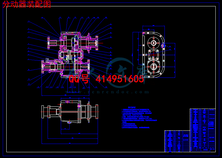
矿用半挂车分动器设计【含全套9张CAD图纸】【答辩毕业资料】

收藏

压缩包内文档预览:(预览前20页/共40页)
预览图 预览图 预览图 预览图 预览图 预览图 预览图 预览图 预览图 预览图 预览图 预览图 预览图 预览图 预览图 预览图 预览图 预览图 预览图 预览图
编号:347102    类型:共享资源    大小:755.26KB    格式:RAR    上传时间:2014-10-24 上传人:好资料QQ****51605 IP属地:江苏
45
积分
关 键 词:
半挂车 分动器 设计 全套 cad 图纸 答辩 毕业 资料
资源描述:

【温馨提示】 购买原稿文件请充值后自助下载。

[全部文件] 那张截图中的文件为本资料所有内容,下载后即可获得。


预览截图请勿抄袭,原稿文件完整清晰,无水印,可编辑。

有疑问可以咨询QQ:414951605或1304139763


矿用半挂车分动器设计
摘  要
本设计主要了解矿用半挂车,以及矿用半挂车的载重,常见矿用半挂车的分动器基本原理和基本结构的型式,矿用半挂车属于非公路运输用的重型和超重型自卸挂车主要承担大型矿山、工程等运输任务,工程方面,比一般载重车更耐用,工作环境恶劣、负载重、劳动强度高。分动器的功用就是将分动器输出的动力分配到各驱动桥,并且进一步增大扭矩。分动器也是一个齿轮传动系统,它单独固定在车架上,其输入轴与分动器的输出轴用万向传动装置连接,分动器的输出轴有若干根,分别经万向传动装置与各驱动桥相连。本设计主要说明了分动器的设计计算过程。设计部分较详细的叙述了分动器的设计过程,选择结构方案、主要参数、齿轮设计、轴设计、计算校核、其他结构部件的设计。

关键词:矿用半挂车分动器;齿轮;轴

Design of Power Transfer Case for the mine Semi-trailer
Abstract
This design mainly know mine semi-trailer, and mine semi-trailer truck, common mining semi-trailer transfer basic principle and basic structure of the model, mining semi-trailer belongs to the highway transportation of heavy and super-heavy dump trailer mainly bear the transportation tasks such as large-scale mining, engineering, engineering, the truck is more durable than normal, work environment bad, negative load, high labor intensity. Transfer function is to transfer the output of the power allocated to each drive axle, and further increase torque. Transfer box is a gear transmission system, it separately fixed on the frame, its input shaft connected to the transfer box output shaft with a universal transmission device, there are a few root transfer box output shaft, respectively by the universal driving device connected with the drive axle. This design mainly illustrates the design and calculation of transfer process. Design part in detail describes the transfer of the design process, choose the structure scheme, the main parameter, design of gear, shaft structure design, calculation and checking, other parts of the design

Keywords: mine semi-trailer; gear;shaft

目  录
1绪论…………………………………………………………………………………1
1.1概述.....................................................................................................................…1
1.2分动器简介..................…..…………………………………………………….....1
 1.2.1带轴间差速器的分动器…………....................................................................1
 1.2.2不带轴间差速器的分动器…………................................................................2
 1.2.3装有超越离合器的分动器…………................................................................2
1.3分动器的构造及原理....................................................................................…2
1.4分动器的轮型..................…..………………………………..……………...…....2
1.4.1分时四驱............................................................................................................2
1.4.2全时四驱............................................................................................................2
1.4.3适时驱动............................................................................................................3
1.5分动器结构方案的选择.........................................................................................3
1.6完成本课题的工作方案及进度计划(按周次填写)…..……………………...5
1.7毕业设计的工作量要求…..………………………………...……………………5
2分动器主要参数的选择………………………………………………………6
2.1档数及传动比……………………………………………………………………6
2.2中心距.................……………………………………………………………  …7
2.3齿轮参数.................……………………………………………………    ……7
2.3.1齿轮模数...........................................................................................................7
2.3.2齿形、压力角、螺旋角β和齿宽.................................  .............................8
2.4高低档传动比及其齿数的确定………  ………………………………………9
2.4.1确定抵挡齿轮的齿数........................................................................................9
2.4.2确定高挡齿轮的齿数........................................................................................9
3分动器齿轮强度计算及材料选择…………………………………………11
3.1齿轮失效形式与原因…………………………………………………………11
3.2齿轮强度计算与校核…………………………………………………………11
3.2.1斜齿轮弯曲应力..............................................................................................11
3.2.2齿轮接触应力..................................................................................................12
4轴的计算与校核………………………………………………………………14
4.1轴的失效形式及设计准则……………………………………………………14
4.2轴的计算..............……………………………………………………………14
4.2.1输入轴的初选及校核......................................................................................14
4.2.2输出轴的初选及校核......................................................................................15
4.3分动器轴承的选择………………………………………………...............……15
 4.3.1轴的结构设计..................................................................................................15
4.4键的计算...............................................................................................................18
5同步器……………………………………………………………………………20
5.1同步器的结构类型…………………………………………………………20
5.2锁环式同步器的工作原理……………………………………………………20
5.3惯性锁止式同步器的主要结构参数…………………………………………22
5.3.1摩擦锥面的半锥角和摩擦系数f………………………………………....22
5.3.2摩擦锥面的平均半径和同步锥环的镜像厚度.....................................22
5.3.3摩擦锥面的工作面宽..................................................................................22
5.3.4锁止角β...........................................................................................................23
5.3.5同步时间与轴向推力.............................................................................23
5.3.6同步器摩擦副的材料......................................................................................23
6工艺分析................................................................................................................24
6.1壳体加工工艺.......................................................................................................24
6.2拨叉加工工艺.......................................................................................................25
6.3齿轮加工工艺.......................................................................................................25
6.4轴的加工工艺.......................................................................................................25
6.5总成的装配...........................................................................................................26
7总结…………………………………………………………………......…………28
参考文献………………………………………………………………………...…29
致谢……………………………………………………………………………….....30
毕业设计(论文)知识产权声明…………………………………………….....31
毕业设计(论文)独创性声明………………………………………………….....….32


1  绪论
1.1概述
本课题主要研究矿用半挂车分动器设计,在多轴驱动的汽车上,为了将变速器输出的动力分配到各驱动桥,通常装有分动器。矿用半挂车的牵引车是在矿车底盘基础上改进设计的双后桥驱动结构,针对桥驱动结构设计中的关键设备—专用分动器,通过分析双后桥驱动原理以及分动器的原理和功能,根据动力分配、底盘结构、传递扭矩及传动方式的要求,确定出分动器的设计方案和整体结构特点[1]。在近百年中,汽车设计技术也经历了由经验设计发展到以科

内容简介:
毕业设计(论文)外文翻译 系 (部): 机电信息系 专 业: 机械设计制造及其自动化 班 级: 学 生: 学 号: 指导教师: 20012年3月2日外文原文Automotive sub-actuators tooth side clearance adjustment optimization techniquesAurelian Vadean , Dimitri Leray , Jean GuillotAdepartment of Mechanical Engineering, Ecole Polytechnique de Montreal, P.O. Box 6079, Station Centre-Ville,Montreal, Qubec, Canada H3C 3A7Blaboratoire de Genie Mecanique de Toulouse - COSAM, INSA Toulouse, 135 Avenue de Rangueil,Toulouse Cedex 4, 31077, FranceAbstract: automotive sub-actuator main gear gap analysis and research, drawn shell adjusting shim thickness splitter assembly performance impact of substance. Based on the relative measurement principle developed sub-actuator shell bearing the adjustment shims preselection system, analysis of the measurement data and uncertainty assessment. Practice has proved that the system can effectively select the appropriate gasket meet pairing arc gear assembly, improve production efficiency, and quality of assembly, the key process for the production of automotive sub-actuator to provide a reliable guarantee.Iso basic skills with the power emitted by the engine to the drive wheels of the car, its primary task is to work together with the car engine, in order to ensure that the car in normal driving under different conditions of use, and has good power and fuel economy. Automotive sub-actuators Usually by the clutch, transmission, universal transmission and main reducer, differential and axle shafts.1 IntroductionAutomotive sub-actuators mounted on the transmission of multi-bridge driver for transmission and distribution of power to each drive axle, doubles as the use of auxiliary transmission. S504 sub-actuators using spiral bevel gear. The the arc gear Vice backlash sub actuator life to drive one of the key factor of stability. The gap is too large, the gearbox will produce noise, vibration; contrary, will aggravate the wear of teeth, appeared gear killed even teeth broken 1. Car usually used the axial shim adjustment method to adjust the tooth side gap, Figure 1 is a vehicle master teeth installation position diagram, the car stars Activity ASSY assembly process, a pair of gears meshing accuracy is through a series of tolerance band different, the adjusting washer of a high surface finish is to be guaranteed. Gasket height and flatness of small changes, all will have a tremendous impact on the efficiency and life of the sub-actuators. Sub-actuators on the domestic auto assembly line (including foreign auto parts enterprises in some branch) main gear assembly assembly is mainly dependent on the experience of the workers, by hand, to the seat of your pants select adjusting shim, its production low efficiency, high failure rates, and assembly quality is difficult to guarantee. After careful analysis of the problems of the traditional assembly methods, S504 points based on the moving assembly assembly process, according to the requirements of the process quality, design the case bearing adjustment shims preselection machine. The preselection is capable of accurately measuring the S504 sub-actuators tooth installation size, position, and thus the best adjustment shims value elected guarantee gears meshing accuracy.The role of the cardan transmission apparatus is connected to the transmission output shaft are not in the same straight line and the main gear box input shaft, and to ensure that in the case of frequently changing the angle and the distance between the axes of the two power transmission reliably. It is composed mainly by universal joints, drive shaft and intermediate support. The installation must be the drive shaft at both ends of the universal joint fork in the same plane.Main reducer car Iso reduce speed and increase the torque of the main components. On the the engine longitudinal automotive, main reducer bevel gear drive to change the momentum direction. When the normal driving of the vehicle, the engine speed is usually about 2000 to 3000r/min, if the such a high speed rely gearbox to lower down, then the pair of gears in the gearbox transmission ratio need great, and the gear pairs of the transmission The radius ratio of the two gears the greater the larger the ratio, in other words, the size of the transmission will be greater. In addition, the spin-down torque inevitably increase, and will increase the transmission load of the gearbox and gearbox after a transmission mechanism. Therefore, the differential in power to the drive wheels to the left and right shunt before setting a main gear box, drive components such as the gearbox, the splitter in front of the main gear box can be universal transmission torque transmitted is reduced, you can also make the size of the gearbox, the reduced mass, manipulation and effort. When the turning of the vehicle when traveling, and the distance of the left and right wheels at the same time rolling across different, If both sides of the drive wheels only to the root rigid shaft drive, the two angular velocity must be the same, thus, when the vehicle is cornering will inevitably produce the wheels relative to the ground surface slide phenomenon. This will enable the steering difficulties, the automobile power consumption is increased, and accelerated wear of certain parts and the tire of the sub-actuator. Therefore, we need within the drive axle member - differential device having a differential action, and so that both left and right drive wheels can be rotated to different angular velocities. Thus, the automotive splitter reasonable design is very important. Automotive sub-actuator design, mainly through experience design calculated cross shaft universal joints, drive shaft, final drive, differential various parts of the main selection and design of structural parameters, and then by hand to map out the two-dimensional drawings of the cross shaft universal joints, drive shaft, the main reduction gear, differential, etc., the product trial design and put into process often problems to go through a lot of changes, which makes the performance of the products and there is no guarantee that the quality and long product development cycle, and the use of human and material resources, resulting in the design and development costs are relatively high. , The increasingly fierce competition in the market economy mechanism, this design approach has been far from meeting. Therefore, motivated rapid development trend of computer technology, the application of computer technology to the development of professional software is used in more and more, and more widely in the development and design of a variety of products. Entities of automotive sub-actuator design can now draw relevant parameters directly using three-dimensional mapping software to various parts of clutch three-dimensional solid modeling, assembly, so you can be three-dimensional to visually see the design of automotive sub-actuators the performance of the product development and design to make the optimal purpose. This computer the software aided drafting not only shorten the product development cycle, but also improve the quality of the product, and greatly reduce the cost of product development, so that will make our products more competitive in the fierce competition in the market economy.2 System design ideas S504 moving assembly structure analysis, the The Iso shell side bearing adjusting shim role: to ensure the the driven gear installation of center distance, adjust the side teeth meshing gap. According to their structural form (Figure 2), to establish the size of the chain as follows:Adjust the shim thicknessAmongA1: the shell with sub-actuators cover the joint surface to the splitter shell gear shaft gear end bearing axial positioning surface distance;A2: the shell with sub actuator cover a combination of the distance from the surface to the main gear shaft axis;A3: dorsal tooth to the teeth end distance of the bearing outer ring face, that bearing high total;52.3 (Unit: mm): the theory of driven gear is installed from the.In the overall size of the chain, adjust the shims to compensate for the ring. When assembled, the rolling bearing in the pre-load state, and adjusting the main, the axial position of the gear, so that the contact spots of assembly requirements 2. Thus, in the Lateral containment pad shims of appropriate thickness, has a crucial role to ensure the performance of the entire sub-actuator.According to the splitter the tooth assembly process requirements, combined with the specific structure of the DUT relative measurement method (Figure 3), which uses high-precision displacement sensor to measure the object A (calibration), read out the sensor compression The amount; measurement of the object B (DUT), read out of the sensor the amount of compression, compressed difference between the amount of the two measurements, to arrive at the height of the workpiece, which is measured by the high-precision measuring instruments 3. Such measurement method has a small range, high accuracy, zero adjustable by the ambient temperature changes affect small advantages.3 System Construction and Analysis3.1 Construction and measurement capabilities Dynamic monitoring and control of the measurement system uses computer technology to the various states in the measurement process real-time data acquisition, processing, and control the entire process by implementing agencies (such as cylinder, etc.), in order to achieve the measurement pad selection, system structure as Figure 4.The measurement methods are as follows: (1) bits are placed in a special jig, the splitter housing to be fitted with a pair of rotating clamping cylinder sandwiched splitter housing two epitaxial boss, so that the splitter shell joints securement measurement platform, measured by the displacement sensor, thereby calculating. (2) through (wherein the series, in order to achieve the dual-stroke function) cylinder control V-type swing frame walking twice repeatedly measured by the displacement sensor, as well as the minimum amount of compression and A2 values calculated by formula. (3) through a rotary clamping calibration bearing control cylinder, so that the whereabouts of the pressure head, the calibration bearing calibration, note the calibration values; remove calibration bearings put on the front step coming to press fitted splitter driven gear bearing, measured to obtain the measurement values, to thereby obtain. (4) By the above-mentioned measurement, can be obtained by the splitter shell bearing adjusting shim thickness, which is measured by the coordinate measuring machine precision data. Gives the best gasket combination (5) According to the results of the data processing and display system displays the location of the gasket, and lightbox; ancillary gasket retest mechanism (controlled by the cylinder) the thickness of the selected spacer multiplexed measured, elected gasket fully meet the assembly requirements.3.2 Measurement Data AnalysisPrevious step S504 actuator assembly line assembled components on the bench, and the pressure bearing inner race of the teeth on the line, according to rules operating points actuator shell bearing adjustment shims preselection system measurement selected pad. The measurement results are recorded as follows:Form 1 of the same product (multiple measurements) Unit: mmNo. 1 2 3 4 5 6 7 8 9 10Actual gasket thickness 1.803 1.802 1.796 1.794 1.801 1.803 1.7991.795 1.796 1.799Table 2 Unit: mmItem No. 01 02 0,304,050,607,080,910Actual gasket thickness 2.031 2.124 1.845 1.962 1.976 2.268 2.2672.768 2.524 1.569 Table 1 shows that the average thickness of the measured gasket 1.799mm, repeat level accuracy can be achieved.By table 2, for the different sub-actuators, the adjustment shim thickness of its shell bearing is not the same, is mainly generated by the casting of housing size of the error, processing is generated in the teeth when the size of the error and the bearing dimension accuracy caused .3.3 Uncertainty Evaluation of measurement results 4 Standard uncertainty; inputs standard main source of uncertainty is the offset and linear repeatability uncertainty component; stability due to uncertainty components, the above can be a Class B assessed . Assessment of the uncertainty components (1) to offset and linearityThe main factors for the displacement sensor offset and linearity uncertainty caused by the measurement system measurement error caused by standard uncertainty (including the characteristics of the sensor itself, and whether it is properly calibrated). Zhongyuan meter factory inductive displacement sensor in the system, given its technical indicators measuring accuracy, it is estimated that the measurement error is uniformly distributed in this interval, and there is a higher probability of confidence interval half-width contains factor, Therefore, in order to reduce the offset error, reducing the uncertainty it caused, you can proceed from the error correction and guaranteed accuracy of the measurement system. (2) repeatability uncertainty component of the assessment Repeatability uncertainty component (3) assessment of stability due to the uncertainty components Observation period of 12 hours, the measurement system drift to almost 0. Due to the resolution of the reason for more subtle changes in the system can not be measured, there is a rounding error. Based on the principle of error rounding, we take the stability of the error. To sum up, the system combined standard uncertainty for this, according to the analysis of the measurement system accuracy specifications shell bearing adjustment shims preselection system Iso Uncertainty Evaluation. Adjusting washer set automatically selected value 1.799mm, can be expressed as; in parentheses are given by standard deviation, and the previous result with the same units of measurement.4 summarizesThe automotive sub actuator multi-bridge drive vehicle powertrain components, the reasonable gear meshing gap is an important guarantee for its excellent performance. Engineering Technology Research Institute of Hefei University of automotive equipment to undertake the project car splitter assembly assembly technology developed points move in Shell bearing adjustment shims the preselection machines and equipment have been put into operation, a sub-actuator assembly efficiency / 3min, after testing, the main gear backlash between basic 0.09-0.11mm, in line with the technical requirements of the product in the state of assembly, reinstall rate of less than 10%. Practice has proved that the device can be accurately selected to ensure the car Iso main gear meshing accuracy adjustment gasket production ergonomics and assembly quality are greatly improved, thus greatly improving the quality and reliability of the splitter assembly sex.外文翻译汽车分动器齿侧间隙调整优化技术作者:奥里安 韦迪纳,*,迪米特里 尼瑞巴 ,让 癸乐特布加拿大H3C公司3A7,魁北克,蒙特利尔,沙田,车站中心,蒙特利尔Ecole理工学院,机械工程系,P.O 6079信箱摘要:通过对汽车分动器主被齿轮啮合间隙的分析和研究,得出壳体调整垫片的厚度对分动器总成性能影响的实质。本文基于相对测量原理,研制出分动器壳轴承调整垫片预选系统,对测量数据进行分析以及不确定度评定。实践证明,该系统能有效选取满足配对弧齿轮装配的合适垫片,改善了生产工效和装配质量,为汽车分动器生产的关键工序提供了可靠保证。1 前言汽车分动器装于多桥驱动的变速器之后,用于传递和分配动力至各驱动桥,兼作副变速器之用。S504分动器采用弧齿锥齿轮传动。弧齿齿轮副侧隙是影响分动器使用寿命、传动平稳性的关键因素之一。间隙太大,齿轮箱会产生噪声、振动;反之,会加剧轮齿的磨损,出现齿轮咬死甚至断齿现象1。汽车上通常采用轴向垫片调整法来调整齿侧间隙,图1是汽车主被齿安装位置示意图,在汽车分动器总成的装配过程中,齿轮副的啮合精度是通过一系列公差带不同、表面光洁度很高的调整垫片来保证的。垫片高度及平整度上的微小变化,都将对分动器的效率与寿命产生巨大影响。目前国内汽车装配线(包括外资汽车及其零部件企业在中国的一些分公司)上的分动器主被齿轮总成的装配主要是依赖工人的经验,通过手工凭感觉选取调整垫片,其生产效率低,返修率高,装配质量难以保证。针对传统装配方法存在的问题,在仔细分析了S504分动器总成装配工艺的基础上,根据其工艺质量的要求,设计了壳体轴承调整垫片预选机。该预选机能够准确地测出S504分动器被齿的安装尺寸、位置,从而选出保证齿轮副啮合精度的最佳调整垫片值。分动器的基本功用是将发动机发出的动力传给汽车的驱动车轮,它的首要任务就是与汽车发动机协同工作,以保证汽车能在不同使用条件下正常行驶,并具有良好的动力性和燃油经济性。汽车分动器一般由离合器、变速器、万向传动装置、主减速器、差速器和半轴等组成。万向传动装置的作用是连接不在同一直线上的变速器输出轴和主减速器输入轴,并保证在两轴之间的夹角和距离经常变化的情况下,仍能可靠地传递动力。它主要由万向节、传动轴和中间支承组成。安装时必须使传动轴两端的万向节叉处于同一平面。主减速器是汽车分动器中减小转速、增大扭矩的主要部件。对发动机纵置的汽车来说,主减速器还利用锥齿轮传动以改变动力方向。汽车正常行驶时,发动机的转速通常在2000至3000r/min左右,如果将这么高的转速只靠变速箱来降低下来,那么变速箱内齿轮副的传动比则需很大,而齿轮副的传动比越大,两齿轮的半径比也越大,换句话说,也就是变速箱的尺寸会越大。另外,转速下降,而扭矩必然增加,也就加大了变速箱与变速箱后一级传动机构的传动负荷。所以,在动力向左右驱动轮分流的差速器之前设置一个主减速器,可使主减速器前面的传动部件如变速箱、分动器、万向传动装置等传递的扭矩减小,也可以使变速箱的尺寸、质量减小,操纵省力。 当汽车转弯行驶时,左右车轮在同一时间内滚过的距离不同,如果两侧驱动轮仅用以根刚性轴驱动,则二者角速度必然相同,因而在汽车转弯时必然产生车轮相对于地面滑动的现象。这将使转向困难,汽车的动力消耗增加,分动器内某些零件和轮胎加速磨损。所以,我们需要在驱动桥内装置具有差速作用的部件差速器,使左右两驱动轮可以以不同的角速度旋转。由此可见,对汽车分动器进行合理的设计是非常重要的。对于汽车分动器的设计,过去主要是以通过经验设计法算出十字轴万向节、传动轴、主减速器、差速器等的各个零部件主要的结构参数的选择与设计,然后通过手工绘制出十字轴万向节、传动轴、主减速器、差速器等的二维工程图,设计的产品试制和投产过程中经常会出现问题,要经过很大的改动,这样使得产品的性能和质量没有保证,而且产品的开发周期长,动用的人力物力也比较大,造成设计开发成本也比较高。特别是在现在市场经济机制下,竞争越来越激烈,这种设计方法已经远远不能适应了。因此,在计算机技术快速发展趋势的促动下,应用计算机技术开发的相应的专业软件应用于各种产品的开发设计中越来越多,也越来越广。现在对汽车分动器的设计可以在得出相关参数后直接利用三维制图软件进行离合器各个零部件的三维实体建模、装配,这样可以立体的直观的看到所设计的汽车分动器的实体以使所开发设计的产品的性能达到最优的目的。这样利用电脑软件辅助制图不仅缩短了产品的开发周期,而且也提高了产品的质量,大大降低了产品的开发成本,这样也就使产品在激烈的市场经济竞争中更具有竞争力。2系统设计思想 由S504分动器总成结构分析可知,分动器壳轴承调整垫片的作用是:保证从动齿轮安装中心距,调整齿侧啮合间隙。依其结构形式(图2),建立如下所示的尺寸链:调整垫片厚度其中A1:分动器壳与分动器盖的结合面到分动器壳被齿轴被齿端轴承轴向定位面的距离;A2:分动器壳与分动器盖的结合面到主齿轴轴线的距离;A3:被齿齿背到被齿端轴承外圈端面的距离,即轴承总高;52.3(单位:mm):从动齿轮理论安装距。在整个尺寸链中,调整垫片为补偿环。装配时,滚动轴承处于预紧状态,调整主、被齿轮的轴向位置,使接触斑点达到装配要求2。因而,在分动器壳内垫上适当厚度的垫片,对保证整个
温馨提示:
1: 本站所有资源如无特殊说明,都需要本地电脑安装OFFICE2007和PDF阅读器。图纸软件为CAD,CAXA,PROE,UG,SolidWorks等.压缩文件请下载最新的WinRAR软件解压。
2: 本站的文档不包含任何第三方提供的附件图纸等,如果需要附件,请联系上传者。文件的所有权益归上传用户所有。
3.本站RAR压缩包中若带图纸,网页内容里面会有图纸预览,若没有图纸预览就没有图纸。
4. 未经权益所有人同意不得将文件中的内容挪作商业或盈利用途。
5. 人人文库网仅提供信息存储空间,仅对用户上传内容的表现方式做保护处理,对用户上传分享的文档内容本身不做任何修改或编辑,并不能对任何下载内容负责。
6. 下载文件中如有侵权或不适当内容,请与我们联系,我们立即纠正。
7. 本站不保证下载资源的准确性、安全性和完整性, 同时也不承担用户因使用这些下载资源对自己和他人造成任何形式的伤害或损失。
提示  人人文库网所有资源均是用户自行上传分享,仅供网友学习交流,未经上传用户书面授权,请勿作他用。
关于本文
本文标题:矿用半挂车分动器设计【含全套9张CAD图纸】【答辩毕业资料】
链接地址:https://www.renrendoc.com/p-347102.html

官方联系方式

2:不支持迅雷下载,请使用浏览器下载   
3:不支持QQ浏览器下载,请用其他浏览器   
4:下载后的文档和图纸-无水印   
5:文档经过压缩,下载后原文更清晰   
关于我们 - 网站声明 - 网站地图 - 资源地图 - 友情链接 - 网站客服 - 联系我们

网站客服QQ:2881952447     

copyright@ 2020-2025  renrendoc.com 人人文库版权所有   联系电话:400-852-1180

备案号:蜀ICP备2022000484号-2       经营许可证: 川B2-20220663       公网安备川公网安备: 51019002004831号

本站为文档C2C交易模式,即用户上传的文档直接被用户下载,本站只是中间服务平台,本站所有文档下载所得的收益归上传人(含作者)所有。人人文库网仅提供信息存储空间,仅对用户上传内容的表现方式做保护处理,对上载内容本身不做任何修改或编辑。若文档所含内容侵犯了您的版权或隐私,请立即通知人人文库网,我们立即给予删除!