说明书.doc

大流量柱塞泵设计【11张CAD图纸和毕业论文】【答辩通过】

收藏

资源目录
跳过导航链接。
压缩包内文档预览:(预览前20页/共104页)
预览图 预览图 预览图 预览图 预览图 预览图 预览图 预览图 预览图 预览图 预览图 预览图 预览图 预览图 预览图 预览图 预览图 预览图 预览图 预览图
编号:362604    类型:共享资源    大小:10.64MB    格式:RAR    上传时间:2014-11-08 上传人:好资料QQ****51605 IP属地:江苏
45
积分
关 键 词:
流量 柱塞 设计 cad 图纸 毕业论文 答辩 通过
资源描述:

【温馨提示】 购买原稿文件请充值后自助下载。

[全部文件] 那张截图中的文件为本资料所有内容,下载后即可获得。


预览截图请勿抄袭,原稿文件完整清晰,无水印,可编辑。

有疑问可以咨询QQ:414951605或1304139763


摘  要

柱塞式往复泵的突出优点是:可获得高的排压,且流量与压力无关,适应输送介质十分广泛,吸入性能好,效率高,泵的性能不随压力和输送介质粘度的变动而变动.在当今世界能源紧缺的形势下,往复泵作为节能产品,在石油开发、管道输煤、煤气化工、电站排渣、矿山开采等方面起着重要作用,而且在压力容器检测和实现现代化石油化工工业全面自动化方面也是不可缺少的品种.近年来,其产量明显增长,证实了它在国民经济发展中的地位.
柱塞泵主要用于国内上有关的国民经济部门,该技术在我国的煤炭工业上也发挥其重要作用.
本说明书从以下几个方面介绍了五柱塞泵的设计.
本泵设计时尽可能考虑实现“条例化、通用化、标准化”以利加工、制造、使用和维修.首先搞清楚柱塞泵的分类及其发展历史再说明了柱塞泵的工作原理.
然后选择了电机、减速器等部件,最主要的是五曲轴及连杆液缸体等主要零部件的设计计算,最后是销、阀、箱体等的选择以及泵的保养、维修、安全使用等等.

关键词:柱塞泵 ;五柱塞 ;煤炭 ;分类


ABSTRACT

Reciprocating pump the plunger prominent advantages are: the row will be high pressure, and the flow has nothing to do with the pressure to adapt to a wide range transmission medium, inhalation good performance, high efficiency, not with the performance of pump pressure and transmission medium viscosity change in the movement . In today's world energy shortage situation,reciprocating pump as energy-saving products, in the development of oil, coal handling pipes, gas chemical industry, power plants slag discharge, such as mining plays an important role, and pressure vessels in the detection and modernization Petrochemical Comprehensive industrial automation is also indispensable varieties. In recent years, significant growth in its production, confirmed in the position of national economic development.
Piston pump used on the domestic economic sector, the technology in China's coal industry has also played an important role.
The statement from the following areas on a five-piston pump design.
The pump designed to achieve as much as possible to consider "the, universal, standardized" to facilitate the processing, manufacture, use and maintenance. Piston pump first make clear the historical development of the Classification and again that the principle of the piston pump.
Then select the motor, reducer, and other components, most notably the five-cylinder crankshaft and connecting rod, and other major parts of the design basis, the sale is final, valves, tank and pump, and so the choice of the maintenance, repair, security, use And so on.

Keyword:
   Piston pump ;five plunger ;coal ;Category


目    录

一 概述 1
1.1往复泵的发展概况 1
1.2往复泵的原理及特点  1
1.2.1往复泵的原理 2
1.2.2往复泵的特点 2
1.3往复泵的分类 4
1.4往复泵的应用与发展 6
二 方案论证 9
2.1大流量柱塞泵 9
2.1.1柱塞泵的基本原理 9
2.1.2柱塞泵的分类 10
2.1.3方案确定 18
三 主要参数的设计 22
3.1泵内主要参数的计算 22
3.2原动机的选择 23
3.3运动与动力参数计算 24
四 齿轮传动设计 26
4.1齿轮的设计 26
4.1.1按照齿面接触疲劳强度计算 26
4.1.2齿轮的基本几何参数 32
4.2齿轮轴的结构设计及强度计算 33
4.2.1齿轮轴的结构设计 34
4.2.2齿轮轴的强度校核 35
4.2.3齿轮轴轴承寿命计算 40
五 传动端结构设计 41
5.1曲轴连杆机构的运动分析 41
5.2曲轴的结构设计 42
5.2.1主要尺寸的初步确定 45
5.2.2曲轴的静强度校核 47
5.3主轴承寿命计算 67
5.4连杆的结构设计 68
5.4.1确定连杆的主要尺寸 69
5.4.2连杆的强度及稳定性校核 74
5.4.3连杆大头轴瓦的计算 82
5.5十字头的结构设计 84
5.5.1确定十头字主要尺寸 85
5.5.2十字头强度校核 86
六 液力端结构设计 89
6.1液缸体的设计计算 89
6.2柱塞的结构尺寸 89
6.3泵阀(吸、排液阀)的设计计算 90
七 机体的结构设计 94
7.1机体主要尺寸的确定 95
结论 97
参考文献 98
翻译部分 100
英文原文 100
中文译文 107
致谢 112

一 概述
1.1往复泵的发展概况
往复泵是工业泵中不可缺少的一类产品.它的突出优点是:可获得高的排压,且流量与压力无关,适应输送介质十分广泛,吸入性能好,效率高,泵的性能不随压力和输送介质粘度的变动而变动.在当今世界能源紧缺的形势下,往复泵作为节能产品,在石油开发、管道输煤、煤气化工、电站排渣、矿山开采等方面起着重要作用,而且在压力容器检测和实现现代化石油化工工业全面自动化方面也是不可缺少的品种.近年来,其产量明显增长,证实了它在国民经济发展中的地位.
1.2 往复泵的原理及特点


1-泵缸 2-活塞 3-活塞杆
图1-1 往复泵装置简图
1.2.1 往复泵的原理
(一)主要部件:泵缸、活塞,活塞杆及吸人阀、排出阀。
(二)工作原理:活塞自左向右移动时,泵缸内形成负压,则贮槽内液体经吸入阀进入泵缸内。当活塞自右向左移动时,缸内液体受挤压,压力增大,由排出阀排出。
活塞往复一次,各吸入和排出一次液体,称为一个工作循环;这种泵称为单动泵。
活塞往返一次,各吸入和排出两次液体,称为双动泵。
活塞由一端移至另一端,称为一个冲程。
(三)往复泵的流量和压头:
往复泵的流量与压头无关,与泵缸尺寸、活塞冲程及往复次数有关。
单动泵的理论流量为:
   QT=Asn
往复泵的实际流量比理论流量小,且随着压头的增高而减小,这是因为漏失所致。
往复泵的压头与泵的流量及泵的几何尺寸无关,而由泵的机械强度、原动机的功率等因素决定。
(四)往复泵的安装高度和流量调节:
往复泵启动时不需灌入液体,因往复泵有自吸能力,但其吸上真空高度亦随泵安装地区的大气压力、液体的性质和温度而变化,故往复泵的安装高度也有一定限制。
往复泵的流量不能用排出管路上的阀门来调节,而应采用旁路管或改变活塞的往复次数、改变活塞的冲程来实现。往复泵启动前必须将排出管路中的阀门打开。
往复泵的活塞由连杆曲轴与原动机相连。原动机可用电机,亦可用蒸汽机。往复泵适用于高压头、小流量、高粘度液体的输送,但不宜于输送腐蚀性液体。有时由蒸汽机直接带动,输送易燃、易爆的液体。
 1.2.2 往复泵的特点
在离心式和容积式两大类泵中,往复泵属于容积式泵.亦即它也是借助工作腔里的容积周期性变化来达到输送液体的目的的;原动机的机械能经泵直接转化为输送液体的压力能;泵的流量只取决于工作腔容积变化值及其在单位时间内的变化次数(频率),而(在理论上)与排出压力无关.
往复泵和其它类型容积式泵的区别,仅在于它实现工作腔容积变化的方式和结构特点上;往复泵是借助于活塞(柱塞)在液缸工作腔内的往复运动(或通过隔膜、波纹管等挠性元件在工作腔内的周期性弹性变形)来使工作腔容积产生周期性变化的.在结构上,往复泵的工作腔是借助密封装置与外界隔开,通过泵阀(吸入阀和排出阀)与管路沟通或闭合.
往复泵这一实现工作容积变化的方式和结构特点,构成了这类类型泵性能参数和总体结构的一系列特点.这些特点也正是这类类型泵借以生存、竞争和发展的依据:
内容简介:
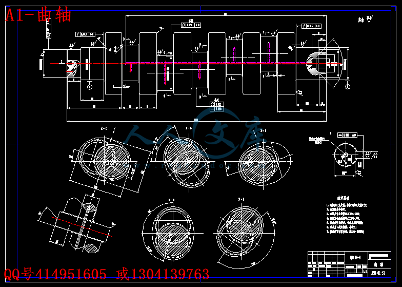
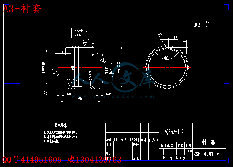
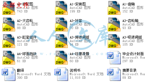
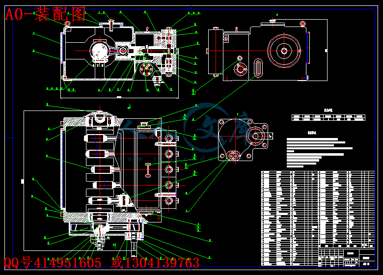
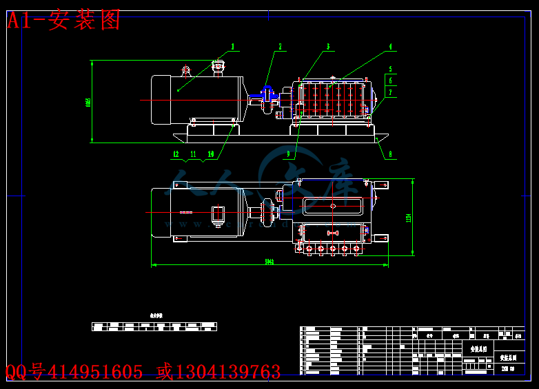
文档包括:说明书一份,100页,29500字左右.翻译一份.图纸共11张:A0-装配图.dwgA1-安装图.dwgA1-曲轴.dwgA2-大齿轮.dwgA3-衬套.dwgA3-齿轮轴.dwgA3-缸套组件.dwgA3-排液阀组.dwgA3-吸液阀组.dwgA4-球面挡块.dwgA4-柱塞滑履.dwg中 国 矿 业 大 学本科生毕业设 计姓 名:菅晓娜菅晓娜 学 号: 2104023521040235 学 院:应用技术学院应用技术学院 专 业:机械工程及自动化机械工程及自动化 设计题目:大流量柱塞泵设计大流量柱塞泵设计 专 题: 指导教师:杨善国杨善国 职 称:副教授副教授 2008 年 06 月 徐州中国矿业大学毕业设计任务书学院 应用技术学院 专业年级 机自 04-1 学生姓名 菅晓娜 任任务务下下达达日日期期:2008 年年 月月 日日毕业设计日期:毕业设计日期: 2008 年年 月月 日至日至 2008 年年 月月 日日毕业设计题目:大流量柱塞泵设计毕业设计题目:大流量柱塞泵设计毕业设计专题题目:毕业设计专题题目:毕业设计主要内容和要求:毕业设计主要内容和要求: 设计一台大流量往复式柱塞泵,公称流量为:500L/min,公称压力为:31.5mpa(1).绘制相关设计图纸 3 张左右(零号);(2).按学校统一要求编写设计说明书,说明书正文 70 页左右;(3).中英文摘要 400 字左右;(4).英文翻译 3000 字左右;(5).参考文献 20 篇左右(其中外文文献 2 篇).院长签字: 指导教师签字:中国矿业大学毕业设计指导教师评阅书指导教师评语(基础理论及基本技能的掌握;独立解决实际问题的能力;研究内容的理论依据和技术方法;取得的主要成果及创新点;工作态度及工作量;总体评价及建议成绩;存在问题;是否同意答辩等):成 绩: 指导教师签字: 年 月 日中国矿业大学毕业设计评阅教师评阅书评阅教师评语(选题的意义;基础理论及基本技能的掌握;综合运用所学知识解决实际问题的能力;工作量的大小;取得的主要成果及创新点;写作的规范程度;总体评价及建议成绩;存在问题;是否同意答辩等):成 绩: 评阅教师签字: 年 月 日中国矿业大学毕业设计评阅教师评阅书评阅教师评语(选题的意义;基础理论及基本技能的掌握;综合运用所学知识解决实际问题的能力;工作量的大小;取得的主要成果及创新点;写作的规范程度;总体评价及建议成绩;存在问题;是否同意答辩等):成 绩: 评阅教师签字: 年 月 日中国矿业大学毕业设计答辩及综合成绩答 辩 情 况回 答 问 题提 出 问 题正 确基本正确有一般性错误有原则性错误没有回答答辩委员会评语及建议成绩:答辩委员会主任签字: 年 月 日学院领导小组综合评定成绩:学院领导小组负责人: 年 月 日摘 要柱塞式往复泵的突出优点是:可获得高的排压,且流量与压力无关,适应输送介质十分广泛,吸入性能好,效率高,泵的性能不随压力和输送介质粘度的变动而变动.在当今世界能源紧缺的形势下,往复泵作为节能产品,在石油开发、管道输煤、煤气化工、电站排渣、矿山开采等方面起着重要作用,而且在压力容器检测和实现现代化石油化工工业全面自动化方面也是不可缺少的品种.近年来,其产量明显增长,证实了它在国民经济发展中的地位.柱塞泵主要用于国内上有关的国民经济部门,该技术在我国的煤炭工业上也发挥其重要作用.本说明书从以下几个方面介绍了五柱塞泵的设计.本泵设计时尽可能考虑实现“条例化、通用化、标准化”以利加工、制造、使用和维修.首先搞清楚柱塞泵的分类及其发展历史再说明了柱塞泵的工作原理.然后选择了电机、减速器等部件,最主要的是五曲轴及连杆液缸体等主要零部件的设计计算,最后是销、阀、箱体等的选择以及泵的保养、维修、安全使用等等. 关键词:柱塞泵 ;五柱塞 ;煤炭 ;分类ABSTRACTReciprocating pump the plunger prominent advantages are: the row will be high pressure, and the flow has nothing to do with the pressure to adapt to a wide range transmission medium, inhalation good performance, high efficiency, not with the performance of pump pressure and transmission medium viscosity change in the movement . In todays world energy shortage situation,reciprocating pump as energy-saving products, in the development of oil, coal handling pipes, gas chemical industry, power plants slag discharge, such as mining plays an important role, and pressure vessels in the detection and modernization Petrochemical Comprehensive industrial automation is also indispensable varieties. In recent years, significant growth in its production, confirmed in the position of national economic development.Piston pump used on the domestic economic sector, the technology in Chinas coal industry has also played an important role.The statement from the following areas on a five-piston pump design.The pump designed to achieve as much as possible to consider the, universal, standardized to facilitate the processing, manufacture, use and maintenance. Piston pump first make clear the historical development of the Classification and again that the principle of the piston pump.Then select the motor, reducer, and other components, most notably the five-cylinder crankshaft and connecting rod, and other major parts of the design basis, the sale is final, valves, tank and pump, and so the choice of the maintenance, repair, security, use And so on.Keyword: Piston pump ;five plunger ;coal ;Category目 录一一 概述概述 .11.1 往复泵的发展概况.11.2 往复泵的原理及特点. 11.2.1 往复泵的原理.21.2.2 往复泵的特点.21.3 往复泵的分类.41.4 往复泵的应用与发展.6二二 方案论证方案论证 .92.1 大流量柱塞泵.92.1.1 柱塞泵的基本原理.92.1.2 柱塞泵的分类.102.1.3 方案确定.18三三 主要参数的设计主要参数的设计 .223.1 泵内主要参数的计算.223.2 原动机的选择.233.3 运动与动力参数计算.24四四 齿轮传动设计齿轮传动设计 .264.1 齿轮的设计.264.1.1 按照齿面接触疲劳强度计算.264.1.2 齿轮的基本几何参数.324.2 齿轮轴的结构设计及强度计算.334.2.1 齿轮轴的结构设计.344.2.2 齿轮轴的强度校核.354.2.3 齿轮轴轴承寿命计算.40五五 传动端结构设计传动端结构设计 .415.1 曲轴连杆机构的运动分析.415.2 曲轴的结构设计.425.2.1 主要尺寸的初步确定.455.2.2 曲轴的静强度校核.475.3 主轴承寿命计算.675.4 连杆的结构设计.685.4.1 确定连杆的主要尺寸.695.4.2 连杆的强度及稳定性校核.745.4.3 连杆大头轴瓦的计算.825.5 十字头的结构设计.845.5.1 确定十头字主要尺寸.855.5.2 十字头强度校核.86六六 液力端结构设计液力端结构设计 .896.1 液缸体的设计计算.896.2 柱塞的结构尺寸.896.3 泵阀(吸、排液阀)的设计计算.90七七 机体的结构设计机体的结构设计 .947.1 机体主要尺寸的确定.95结论结论 .97参考文献参考文献 .98翻译部分翻译部分 .100英文原文 .100中文译文 .107致谢致谢 .112编号:( )字 号本科生毕业设计大流量柱塞泵设计菅晓娜 21040235机械工程及自动化专业04-1题目: 姓名: 学号: 班级: 二八年六月中 国 矿 业 大 学本科生毕业设 计姓 名:菅晓娜菅晓娜 学 号: 2104023521040235 学 院:应用技术学院应用技术学院 专 业:机械工程及自动化机械工程及自动化 设计题目:大流量柱塞泵设计大流量柱塞泵设计 专 题: 指导教师:杨善国杨善国 职 称:副教授副教授 2008 年 06 月 徐州中国矿业大学毕业设计任务书学院 应用技术学院 专业年级 机自 04-1 学生姓名 菅晓娜 任任务务下下达达日日期期:2008 年年 月月 日日毕业设计日期:毕业设计日期: 2008 年年 月月 日至日至 2008 年年 月月 日日毕业设计题目:大流量柱塞泵设计毕业设计题目:大流量柱塞泵设计毕业设计专题题目:毕业设计专题题目:毕业设计主要内容和要求:毕业设计主要内容和要求: 设计一台大流量往复式柱塞泵,公称流量为:500L/min,公称压力为:31.5mpa(1).绘制相关设计图纸 3 张左右(零号);(2).按学校统一要求编写设计说明书,说明书正文 70 页左右;(3).中英文摘要 400 字左右;(4).英文翻译 3000 字左右;(5).参考文献 20 篇左右(其中外文文献 2 篇).院长签字: 指导教师签字:中国矿业大学毕业设计指导教师评阅书指导教师评语(基础理论及基本技能的掌握;独立解决实际问题的能力;研究内容的理论依据和技术方法;取得的主要成果及创新点;工作态度及工作量;总体评价及建议成绩;存在问题;是否同意答辩等):成 绩: 指导教师签字: 年 月 日中国矿业大学毕业设计评阅教师评阅书评阅教师评语(选题的意义;基础理论及基本技能的掌握;综合运用所学知识解决实际问题的能力;工作量的大小;取得的主要成果及创新点;写作的规范程度;总体评价及建议成绩;存在问题;是否同意答辩等):成 绩: 评阅教师签字: 年 月 日中国矿业大学毕业设计评阅教师评阅书评阅教师评语(选题的意义;基础理论及基本技能的掌握;综合运用所学知识解决实际问题的能力;工作量的大小;取得的主要成果及创新点;写作的规范程度;总体评价及建议成绩;存在问题;是否同意答辩等):成 绩: 评阅教师签字: 年 月 日中国矿业大学毕业设计答辩及综合成绩答 辩 情 况回 答 问 题提 出 问 题正 确基本正确有一般性错误有原则性错误没有回答答辩委员会评语及建议成绩:答辩委员会主任签字: 年 月 日学院领导小组综合评定成绩:学院领导小组负责人: 年 月 日摘 要柱塞式往复泵的突出优点是:可获得高的排压,且流量与压力无关,适应输送介质十分广泛,吸入性能好,效率高,泵的性能不随压力和输送介质粘度的变动而变动.在当今世界能源紧缺的形势下,往复泵作为节能产品,在石油开发、管道输煤、煤气化工、电站排渣、矿山开采等方面起着重要作用,而且在压力容器检测和实现现代化石油化工工业全面自动化方面也是不可缺少的品种.近年来,其产量明显增长,证实了它在国民经济发展中的地位.柱塞泵主要用于国内上有关的国民经济部门,该技术在我国的煤炭工业上也发挥其重要作用.本说明书从以下几个方面介绍了五柱塞泵的设计.本泵设计时尽可能考虑实现“条例化、通用化、标准化”以利加工、制造、使用和维修.首先搞清楚柱塞泵的分类及其发展历史再说明了柱塞泵的工作原理.然后选择了电机、减速器等部件,最主要的是五曲轴及连杆液缸体等主要零部件的设计计算,最后是销、阀、箱体等的选择以及泵的保养、维修、安全使用等等. 关键词:柱塞泵 ;五柱塞 ;煤炭 ;分类ABSTRACTReciprocating pump the plunger prominent advantages are: the row will be high pressure, and the flow has nothing to do with the pressure to adapt to a wide range transmission medium, inhalation good performance, high efficiency, not with the performance of pump pressure and transmission medium viscosity change in the movement . In todays world energy shortage situation,reciprocating pump as energy-saving products, in the development of oil, coal handling pipes, gas chemical industry, power plants slag discharge, such as mining plays an important role, and pressure vessels in the detection and modernization Petrochemical Comprehensive industrial automation is also indispensable varieties. In recent years, significant growth in its production, confirmed in the position of national economic development.Piston pump used on the domestic economic sector, the technology in Chinas coal industry has also played an important role.The statement from the following areas on a five-piston pump design.The pump designed to achieve as much as possible to consider the, universal, standardized to facilitate the processing, manufacture, use and maintenance. Piston pump first make clear the historical development of the Classification and again that the principle of the piston pump.Then select the motor, reducer, and other components, most notably the five-cylinder crankshaft and connecting rod, and other major parts of the design basis, the sale is final, valves, tank and pump, and so the choice of the maintenance, repair, security, use And so on.Keyword: Piston pump ;five plunger ;coal ;Category目 录一一 概述概述 .11.1 往复泵的发展概况.11.2 往复泵的原理及特点. 11.2.1 往复泵的原理.21.2.2 往复泵的特点.21.3 往复泵的分类.41.4 往复泵的应用与发展.6二二 方案论证方案论证 .92.1 大流量柱塞泵.92.1.1 柱塞泵的基本原理.92.1.2 柱塞泵的分类.102.1.3 方案确定.18三三 主要参数的设计主要参数的设计 .223.1 泵内主要参数的计算.223.2 原动机的选择.233.3 运动与动力参数计算.24四四 齿轮传动设计齿轮传动设计 .264.1 齿轮的设计.264.1.1 按照齿面接触疲劳强度计算.264.1.2 齿轮的基本几何参数.324.2 齿轮轴的结构设计及强度计算.334.2.1 齿轮轴的结构设计.344.2.2 齿轮轴的强度校核.354.2.3 齿轮轴轴承寿命计算.40五五 传动端结构设计传动端结构设计 .415.1 曲轴连杆机构的运动分析.415.2 曲轴的结构设计.425.2.1 主要尺寸的初步确定.455.2.2 曲轴的静强度校核.475.3 主轴承寿命计算.675.4 连杆的结构设计.685.4.1 确定连杆的主要尺寸.695.4.2 连杆的强度及稳定性校核.745.4.3 连杆大头轴瓦的计算.825.5 十字头的结构设计.845.5.1 确定十头字主要尺寸.855.5.2 十字头强度校核.86六六 液力端结构设计液力端结构设计 .896.1 液缸体的设计计算.896.2 柱塞的结构尺寸.896.3 泵阀(吸、排液阀)的设计计算.90七七 机体的结构设计机体的结构设计 .947.1 机体主要尺寸的确定.95结论结论 .97参考文献参考文献 .98翻译部分翻译部分 .100英文原文 .100中文译文 .107致谢致谢 .112编号:( )字 号本科生毕业设计大流量柱塞泵设计菅晓娜 21040235机械工程及自动化专业04-1题目: 姓名: 学号: 班级: 二八年六月中国矿业大学2008届本科生毕业设计 第 13 页翻译部分英文原文Hydraulic pumpAbstract:A hydraulic pump unit is encased between a pump body and a pump cover. A bearing hole passes through the pump body and is formed in the pump body. A drive shaft and a bearing bush are inserted into the bearing hole. The drive shaft drives the hydraulic pump unit and the bearing bush supports the drive shaft. At an end portion of the bearing hole, a seal chamber is formed. The seal chamber encases a seal member. An oil groove is formed inside the bearing hole. The oil groove connects the hydraulic pump unit side with the seal chamber and carries hydraulic oil for lubrication. The oil groove is formed in such a manner that a sectional area in the seal chamber side is greater than a sectional area in the hydraulic pump unit side. The bearing bush comprises a plurality of bush pieces arranged at a predetermined interval in an axial direction of the bearing hole. SUMMARY OF THE INVENTION The following is an explanation of one embodiment applied to a hydraulic pump of a power steering of the present invention with reference to the drawings. In the drawings, a reference numeral 1 denotes a pump body made of metallic materials such as aluminum alloy and so on and a reference numeral 2 denotes a pump cover made of metallic materials. The pump body 1 and the pump cover 2 encase a hydraulic pump unit 3. That is, an annular concave portion 4 is formed between the pump body 1 and the pump cover 2. The hydraulic pump unit 3 is installed in the annular concave portion 4. In this embodiment, the hydraulic pump unit 3 is a vane hydraulic pump unit. The hydraulic pump unit 3 includes a cam ring 7 encasing a rotor 6. The rotor 6 comprises a plurality of vanes 5 which are radially movable in and out. Both sides of the cam ring 7 are guided by side plates 8 and 9. A pumping chamber 10 is formed by two adjacent one of the vanes 5 between the cam ring 7 and the rotor 6. The volume of the pumping chamber 10 varies by the rotation of the rotor 6. With this variation, an inhaling zone is formed in a portion increasing in volume and a discharging zone is formed in a portion decreasing in volume. Notch passages 8a and 8b are formed in the side plates 8 and 9. The side plates 8 and 9 face the discharging zone. The notch passages 8a and 9a open radially and outwardly. The oil discharged from the pump is discharged into a discharging chamber (a high pressure chamber) 11 of the annular concave portion 4 of the outer circumference of the cam ring 7. An inhaling port not shown in the drawing is formed in the side plate 9 facing the inhaling zone and passes therethrough. A bearing hole 12 is formed in the pump body 1 and passes through the pump body 1. A seal chamber 13 is formed in an end portion of the bearing hole 12. An oil groove 14 communicating from the hydraulic pump unit 3 side to the seal chamber 13 is formed in the bearing hole 12. The section of the oil groove 14 is a circular arc. the sectional area of the oil groove 14 in the seal chamber 13 side is greater than the sectional area of the oil groove 14 in the hydraulic pump unit 3 side and it is easy to form the oil groove 14 in a casting mold. The oil groove 14 in this embodiment is divided at a substantially center position of the bearing hole 12. However, because the substantially center position of the bearing hole 12 is positioned between a plurality of bush pieces later-mentioned, the substantially center position of the bearing hole 12 is substantially communicated with an interval between the bush pieces. Because the oil groove 14 is divided at the substantially center position of the bearing hole 12, this divided part becomes a so-called labyrinth and a flow resistance is applied to hydraulic oil flowing in the oil groove 14. Therefore, it is possible to decrease the energy of the hydraulic oil flowing into the seal chamber 13. The oil groove 14 can be continuously formed without dividing at the substantially center position of the bearing hole 12. The oil groove 14 can be continuously formed in a taper shape so that the sectional area increases gradually from the hydraulic pump unit 3 side to the seal chamber 13 side. With this structure, the oil groove 14 can lead the leakage oil from the bearing hole 12 of the hydraulic pump unit 3 to the seal chamber 13. The leakage oil from the hydraulic pump unit 3 is the hydraulic oil leaking between the rotor 6 and the side plates 8 and 9 and is a little hydraulic oil leaking from the joint between the pump body 1 and the side plate 9. An inhaling passage 15, a discharging passage 16 and a spool valve receiving bore 17 are formed in the pump body 1. The inhaling passage 15 connects each pumping chamber 10 of the inhaling zone with a storage tank not shown in the drawing. The discharging passage 16 connects each pumping chamber 10 of the discharging zone with the actuator of the power steering not shown in the drawing. One end of the spool valve receiving bore 17 is sealed. The inhaling passage 15 is branched into two directions at the joint facing the side plate 9. At the end portion of the inhaling passage 15, a circular arc shape inhaling port 18 is formed. The inhaling port 18 is formed so that the inhaling port 18 faces the inhaling port, not shown in the drawing, formed in the side plate 9. The inhaling passage 15 is connected with the seal chamber 13 through a low pressure passage 19. The low pressure passage 19 is substantially parallel with the bearing hole 12. The discharging passage 16 is bent radially and outwardly at the joint facing the side plate 9. An orifice passage 21 connected with an inhaling port 20 formed in the side plate 9 is formed in the discharging passage 16. A reference numeral 22 denotes a bearing bush inserted into the bearing hole 12. The bearing bush 22 comprises a plurality of bush pieces 23 positioned at a predetermined interval in the axial direction of the bearing hole 12. In this embodiment, the bearing bush 22 comprises two bush pieces 23 positioned at the interval 1 in the axial direction of the bearing hole 12. The bush piece 23 is formed into a cylindrical shape by rounding a plate member. The inner surface of the bearing bush 22 is smooth. The oil groove is not formed in the bearing bush 22. The interval 1 between the two-bush pieces 23 forming the bearing bush 22 is preferable to be substantially 1/3 of the axial length L of the bearing bush 22 in order to secure the area for supporting the bearing bush 22. In this embodiment, the interval 1 between the bush pieces 23 is substantially 1/5 of the axial length L of the bearing bush 22. A reference numeral 25 denotes a drive shaft for driving the hydraulic pump unit 3. The drive shaft 25 is inserted into the bearing hole 12 in such a manner that the drive shaft 25 is supported by the bearing bush 22. The drive shaft 25 has serrations 26 formed near the forward end. The serrations 26 pass through the through hole 9b of the side plate 9 and are fitted in the serration hole 27 of the rotor 6. With this, the drive shaft 25 is capable of driving the rotor 6 of the hydraulic pump unit 3. The forward end portion of the drive shaft 25 is tapered and loosely fitted in the through hole 8b of the side plate 8. A spool valve 30 controlling the quantity of the oil is slidably movable and is fitted in the spool valve receiving bore 17. The spool valve 30 divides the inside of the spool valve receiving bore 17 into a first pressure chamber 17a and a second pressure chamber 17b. The spool valve 30 is normally biased toward the first pressure chamber 17a side by a spring force of a control spring 31. The control spring 31 is encased in the second pressure chamber 17b. The spool valve 30 closes a drain passage 33 connecting the inhaling passage 15 in a normal condition. In the pump body 1, a passage 35 is formed. The passage 35 is connected with a discharging lot not shown in the drawing in order to connect with the discharging passage 16 and to lead hydraulic oil to the power steering, that is, the actuator not shown in the drawing. The passage 35 is connected with the second pressure chamber 17b through a passage 36. The pressure in the discharging passage 16 is led into the second pressure chamber 17b. A reference numeral 39 denotes a pressure switch mounted on the pump cover 2. The pressure switch 39 comprises a fixed contact 39a and a moving contact 39b. The pressure switch 39 is able to operate according to the pressure of the discharging chamber 11 because the end portion of the moving contact 39b faces a passage 40 connecting with the discharging chamber 11. The pressure switch 39 is thrust into and fixed in the inside of a concave portion 41. The inside of the concave portion 41 is connected with the through hole 9b of the side plate 9 through a radial passage 42 and an axial passage 43. The pump body 1 and the pump cover 2 are connected and fixed with each other by bolts not shown in the drawing. The joint between the pump body 1 and the pump cover 2 is sealed by a seal ring 44 so as to prevent the hydraulic oil discharged into the discharging chamber 11 from leaking to the outside. A reference numeral 45 denotes a seal ring installed between the pump cover 2 and the side plate 8. The seal ring 45 separates the discharging chamber 11 from the through hole 8b of the side plate 8. A reference numeral 46 denotes a seal member. The seal member 46 is installed in the seal chamber 13 and seals the drive shaft 25. With this structure, the drive shaft 25 is rotationally driven through the pulley not shown in the drawing and the rotor 6 connected with the drive shaft 25 is rotationally driven. When the rotor 6 is rotationally driven, with the rotation of the rotor 6, the volume of the inhaling zone increases and the volume of the discharging zone decreases. Hydraulic oil is inhaled from the inhaling passage 15 through the inhaling port 18 into the pumping chamber 10 in the inhaling zone, passes through the pump and is discharged from the pumping chamber 10 in the discharging zone into the discharging chamber 11. The hydraulic oil discharged into the discharging chamber 11 is led to the first pressure chamber 17a through the leading passage 34. The hydraulic oil led into the first pressure chamber 17a is led into the actuator of the power steering not shown in the drawing through the orifice passage 21, the discharging passage 16 and the passage 35. In a normal condition, the spool valve 30 is urged toward the first pressure chamber 17a side by the control spring 31 and closes the drain passage 33 by the land portion 32 of the main body of the spool valve 30. All of the discharged oil led into the first pressure chamber 17a is led into the actuator not shown in the drawing through the orifice passage 21. When the rotational speed of the pump increases, the quantity of the oil discharged from the pump increases and the quantity of the oil discharged from the pump led into the first pressure chamber 17a increases, the hydraulic oil in the first pressure chamber 17a is led into the discharging passage 16 under the limitation of flow by the orifice passage 21, the spool valve 30 moves rightward and compresses the control spring 31 to a predetermined length according to the front and rear differential pressure of the orifice passage 21, opens the drain passage 33 and returns surplus oil from the drain passage 33 to the inhaling passage 15 and the storage tank not shown in the drawing. As the hydraulic pump unit 3 is driven, the hydraulic oil is discharged into the discharging chamber 11 and leaks from a gap formed among the rotor 6 and the side plates 8 and 9 for lubrication. A small amount of the hydraulic oil also leaks from the joint between the pump body 1 and the side plate 9. The leakage oil from the hydraulic pump unit 3 is collected into the bearing hole 12 of the hydraulic pump unit 3 side. That is, the leakage oil from the joint between the rotor 6 and the side plate 9 is led into the through hole 8b and is collected into the bearing hole 12 through the engaging gaps of the serrations 26 and 27 and the through hole 9b of the side plate 9. The leakage oil from the joint between the rotor 6 and the side plate 9 is collected into the bearing hole 12 through the through hole 9b of the side plate 9. The oil collected into the bearing hole 12 of the side plate 9 lubricates the bearing hole 12 and is led into the seal chamber 13 through the oil groove 14 formed in the bearing hole 12. The hydraulic oil led to the seal chamber 13 is sealed by the seal member 46 in the seal chamber 13 and is returned to the inhaling passage 15 and the storage tank not shown in the drawing through the low pressure passage 19. At this time, the leakage oil led into the bearing hole 12 from the hydraulic pump unit 3 is directly supplied from the bearing hole 12 of the hydraulic pump unit 3 side into the inner surface of the bearing bush 22, is led into the seal chamber 13 through the oil groove 14 formed in the bearing hole 12 and is supplied from the seal chamber 13 side into the inner surface of the bearing bush 22. Because a part of the leakage oil led along the oil groove 14 is supplied from the oil groove 14 to spaces neighboring one another, the part of the leakage oil is supplied from the spaces between the bush pieces 23 into the inner surface of the bearing bush 22. The oil supplied to the inner surface of the bush pieces 22 is led into the bearing gap in a state of a wedge. The bearing gap becomes narrower in a rotational direction with the rotation of the drive shaft 25. The oil film pressure caused by the wedge action forms a satisfactory lubricating oil film so that the drive shaft 25 is smoothly supported. The hydraulic oil led from the oil groove 14 into the seal chamber 13 is sealed by the seal member 46 encased in the seal chamber 13. The sectional area of the oil groove 14 in the seal chamber 13 side is formed so as to be greater than the sectional area of the oil groove 14 in the hydraulic pump unit 3 side. The oil groove 14 leads the leakage oil from the hydraulic pump unit 3 to the seal chamber 13. Therefore, when the quantity of the leakage oil from the hydraulic pump unit 3 increases, the flow speed in the oil groove 14 in the hydraulic pump unit 3 side becomes slower than the flow speed in the seal chamber 3 side and the energy of the hydraulic oil led into the seal chamber 13 decreases. Thus, because it is possible to prevent the energy of the hydraulic oil led into the seal chamber 13 from exceeding the sealing ability of the seal member 46, the seal member 46 securely seals the hydraulic oil in the seal chamber 13. Therefore, it is possible to provide a hydraulic pump which can prevent the hydraulic oil from leaking to the outside. When the drive shaft 25 drives the hydraulic pump unit 3, the drive shaft 25 is supported by the bearing bush 22. Because a moderate bearing gap is formed between the bearing bush 22 and the drive shaft 25, the drive shaft 25 can incline in the cylindrical bearing bush 22. This embodiment forms a stable lubricating oil film at both end sides of the bearing bush 22 and prevents an inferior lubrication without letting both end sides of the bearing bush 22 firmly contact the drive shaft 25. That is, because the bearing bush 22 is formed in such a manner that a plurality of bush pieces 23 are positioned at the predetermined interval 1 in the axial direction of the bearing hole 12, a gap (the interval 1) is formed at a substantially center portion of the bearing bush 22. However, the bush pieces 23 are respectively arranged at both end sides of the bearing bush 22. The drive shaft 25 firmly contacts the end sides of the bearing bush 22. The oil groove preventing the lubricating oil film from being formed is not formed at the inner circumference of the bush pieces 23. The oil for lubricating is sufficiently supplied from both end sides of the bearing bush 22 and the bush pieces 23 neighboring with one another to the inner circumference of the bearing bush 22 comprised of each bush piece 23. Therefore, especially at both end sides of the bearing bush 22 the drive shaft 25 firmly contacts, the stable lubricating oil film is formed and the inferior lubrication is prevented. In this embodiment, at the inner circumference of the bearing bush 22, the oil groove 14 is formed. The oil groove 14 connects the hydraulic pump unit 3 side with the seal chamber 13 and flows the hydraulic oil for lubrication. That is, the bearing bush 22 is formed by rounding a plate member. At the inner circumference of this bearing bush 22, the oil groove 14 is formed. The oil groove 14 is obliquely formed as one straight line or two oil grooves 14 are formed so as to cross each other at a substantially center position in such a manner that the bearing bush 22 is expanded into a plate shape. Each oil groove 14 is formed in a taper shape so that each sectional area increases gradually from the hydraulic pump unit 3 side to the seal chamber 13 side. According to this constitution, the leakage oil led into the bearing hole 12 from the hydraulic pump unit 3 is directly supplied from the bearing hole 12 of the hydraulic pump unit 3 side into the inner surface of the bearing bush 22, is led into the seal chamber 13 through the oil groove 14 formed in the inner circumference of the bearing bush 22 and is supplied from the oil groove 14 and the seal chamber 13 side into the inner surface of the bearing bush 22. With this, the drive shaft 25 is smoothly supported. Therefore, in this embodiment, it is possible to provide a hydraulic pump which can prevent the hydraulic oil from leaking to the outside. Because the oil groove 14 is formed in the inner surface of the bearing bush 22, it is possible to decrease the manufacturing man-hour of the bearing hole 12. The above-mentioned description is an explanation of the embodiments of the present invention with reference to the drawings. The present invention is not limited to these embodiments. The present invention can change without departing from the spirit of the present invention. For example, the oil groove 14 formed inside the bearing hole 12 is formed in a substantially straight line in the axial direction of the bearing hole 12, but can be spiral or can be multiple threads. The bush 22 can comprise more than three bush pieces. In this case, each of bush pieces can be positioned at an equal or unequal interval. According to the present invention, it is possible to provide the hydraulic pump which can prevent the hydraulic oil from leaking to the outside中文译文液 压 泵摘要:液压泵构件被装在泵体和泵盖之间。轴承孔穿过整个泵体,并且在泵体上被加工完成。主轴和轴承衬被装在轴承孔里。主轴驱动液压泵并且轴承衬支撑着主轴。在轴承孔的末尾,有一个密封的空间,密封圈就是装在这里的。在轴承孔里加工了一个油槽,它连接了液压泵构件和密封空间,并且提供液压油润滑。密封腔边上的油槽的区域要比液压泵构件旁的油槽区域大。轴承衬由很多个衬套组成,并被装在有一定的轴向间隙的轴承孔里。正文:下面是用这幅图画来解释这液压泵的工作原理。在图中,数字1代表由铝合金这样金属材料做成的泵体,数字2代表由金属材料做成的泵盖。液压泵构件3装在泵体1和泵盖2里。换句话说,环形凹槽被加工在泵体1和泵盖2之间,液压泵构件3被装在环形凹槽4里。在这个实例中,液压泵构件3是叶片泵的零件。液压泵构件3包括定子7和转子6。转子6由多个放射状活动的叶片组成。定子7两边是配流盘8和9。由定子7和转子6之间的两个相邻的叶片5组成了一个密闭容积10。密闭容积10的大小随着转子6旋转而变化。变化是这样的,吸油腔逐渐变大,卸油腔逐渐减少。凹槽通道8a和8b在配流盘8和9 的一边。配流盘8和9的一边正对着卸油腔。凹槽通道8a和8b放射状的开着。泵里的液压油卸载到定子7外围的环形凹槽4里的卸油腔(高压腔)11。在图中没有标出吸油口,它在配流盘9一边正对着吸油腔并且通过配流盘。轴承孔12在泵体1上并通过泵体1。密闭容积13在轴承孔的末端。在轴承孔12上的油槽14连接着液压泵构件3和密闭容积13。部分油槽14是段圆弧。在密闭容积13边的部分油槽14要比在液压泵构件3边的部分油槽14大些。,这样的油槽14很容易铸模形成。这实例中的油槽14被轴承孔12中心位置分割开。然而,因为轴承孔的中心位置被放在后面提到的衬套片之间,所以轴承孔12的中心位置直接连接着衬套片之间的间隙。因为油槽14被轴承孔12中心位置分割开,所以被分割开的部分成为了所谓的闭死区,这样在油槽14中就阻碍了液压油的流动。因此,这有可能减少了进入密闭容积13的液压油的流量。在轴承孔12中心位置不断的形成没有被分开的油槽14。油槽14不断形成锥形形状,以至于液压泵构件3那边的区域变大,而密闭容积边的区域变小。根据这种结构,油槽14能让泄漏的油从液压泵构件3中的轴承孔12流到密闭容积13,液压泵构件3中的露油是从转子6和配流盘8和9泄漏出来的液压油,少量的液压油从泵体1与配流盘9的连接出泄漏出来。进油口15,出油口16和伺服阀接口17在泵体1上。进油口15把吸油腔的每个压油室10和图上没有表示出来的油箱连接着。出油口16把卸油腔的每个压油室10和图上没有表示出来的动力方向盘连接着。伺服阀接口17的一端是封闭的。在与配流盘9的结合面上,进油口15被分为两路。在进油口15的末端,有个圆弧形状的吸油口18。在配流盘9上形成的吸油口1
温馨提示:
1: 本站所有资源如无特殊说明,都需要本地电脑安装OFFICE2007和PDF阅读器。图纸软件为CAD,CAXA,PROE,UG,SolidWorks等.压缩文件请下载最新的WinRAR软件解压。
2: 本站的文档不包含任何第三方提供的附件图纸等,如果需要附件,请联系上传者。文件的所有权益归上传用户所有。
3.本站RAR压缩包中若带图纸,网页内容里面会有图纸预览,若没有图纸预览就没有图纸。
4. 未经权益所有人同意不得将文件中的内容挪作商业或盈利用途。
5. 人人文库网仅提供信息存储空间,仅对用户上传内容的表现方式做保护处理,对用户上传分享的文档内容本身不做任何修改或编辑,并不能对任何下载内容负责。
6. 下载文件中如有侵权或不适当内容,请与我们联系,我们立即纠正。
7. 本站不保证下载资源的准确性、安全性和完整性, 同时也不承担用户因使用这些下载资源对自己和他人造成任何形式的伤害或损失。
提示  人人文库网所有资源均是用户自行上传分享,仅供网友学习交流,未经上传用户书面授权,请勿作他用。
关于本文
本文标题:大流量柱塞泵设计【11张CAD图纸和毕业论文】【答辩通过】
链接地址:https://www.renrendoc.com/p-362604.html

官方联系方式

2:不支持迅雷下载,请使用浏览器下载   
3:不支持QQ浏览器下载,请用其他浏览器   
4:下载后的文档和图纸-无水印   
5:文档经过压缩,下载后原文更清晰   
关于我们 - 网站声明 - 网站地图 - 资源地图 - 友情链接 - 网站客服 - 联系我们

网站客服QQ:2881952447     

copyright@ 2020-2025  renrendoc.com 人人文库版权所有   联系电话:400-852-1180

备案号:蜀ICP备2022000484号-2       经营许可证: 川B2-20220663       公网安备川公网安备: 51019002004831号

本站为文档C2C交易模式,即用户上传的文档直接被用户下载,本站只是中间服务平台,本站所有文档下载所得的收益归上传人(含作者)所有。人人文库网仅提供信息存储空间,仅对用户上传内容的表现方式做保护处理,对上载内容本身不做任何修改或编辑。若文档所含内容侵犯了您的版权或隐私,请立即通知人人文库网,我们立即给予删除!