【温馨提示】 购买原稿文件请充值后自助下载。
以下预览截图到的都有源文件,图纸是CAD,文档是WORD,下载后即可获得。
预览截图请勿抄袭,原稿文件完整清晰,无水印,可编辑。
有疑问可以咨询QQ:414951605或1304139763
叉架加工工艺及夹具设计
【摘要】
叉架零件的主要加工表面是平面及孔系。一般来说,保证平面的加工精度要比保证孔系的加工精度容易。本设计是基于叉架零件的加工工艺规程及一些工序的专用夹具设计。因此,本设计遵循先面后孔的原则。并将孔与平面的加工明确划分成粗加工和精加工阶段以保证孔系加工精度。基准选择以叉架的输入轴和输出轴的支承孔作为粗基准,以底面与两个工艺孔作为精基准。主要加工工序安排是先以支承孔系定位加工出顶平面,再以顶平面与支承孔系定位加工出工艺孔。在后续工序中除个别工序外均用顶平面和工艺孔定位加工其他孔系与平面。支承孔系的加工采用的是坐标法镗孔。整个加工过程均选用组合机床。夹具选用专用夹具,机构可以不必自锁,因此生产效率较高,适用于大批量、流水线上加工,能够满足设计要求。
关键词:叉架类零件;工艺;夹具;
ABSTRACT
The main processing surface foot seat parts is the plane and a series of hole. In general, ensure the machining accuracy of plane than to ensure the accuracy of the processing easily. This design is the special fixture for machining technology for the foot seat parts and process design based on. Therefore, the design follows the surface after the first hole principle. And the hole and the plane processing clearly divided into roughing and finishing stages to ensure machining precision. The supporting hole datum selection to the foot seat of the input shaft and output shaft as a rough benchmark, the bottom surface and the two holes as a precision technology base. The main process of machining technology is first to support hole positioning processing the top plane, and then the top plane and the series of supporting hole location hole processing technology. In addition to the follow-up processes are individual processes with the top plane positioning technology and other processing Kong and plane. Processing support holes using the coordinate boring. The whole process selection of combined machine tool. Clamp by, agencies can not self-locking, therefore the production efficiency is high, suitable for large batch, line processing, can meet the design requirements.
Keywords: foot seat parts; technology; fixture;
目 录
1 加工工艺规程设计 1
1.1 零件的分析 1
1.1.1 零件的作用 1
1.1.2 零件的工艺分析 2
1.2 叉架加工的主要问题和工艺过程设计所应采取的相应措施 2
1.2.1 孔和平面的加工顺序 2
1.2.2 孔系加工方案选择 3
1.3 叉架加工定位基准的选择 3
1.3.1 粗基准的选择 3
1.3.2 精基准的选择 4
1.4 叉架加工主要工序安排 4
1.5 机械加工余量、工序尺寸及毛坯尺寸的确定 6
1.6确定切削用量及基本工时(机动时间) 7
1.7 时间定额计算及生产安排 13
2 钻Φ20孔夹具设计 17
2.1 研究原始质料 17
2.2 定位、夹紧方案的选择 17
2.3切削力及夹紧力的计算 17
2.4 误差分析与计算 18
2.5 钻套、衬套、钻模板设计与选用 19
2.6 夹具体的设计 20
2.7 夹具设计及操作的简要说明 21
总结 22
参 考 文 献 23
致 谢 24
1 加工工艺规程设计
1.1 零件的分析
1.1.1 零件的作用
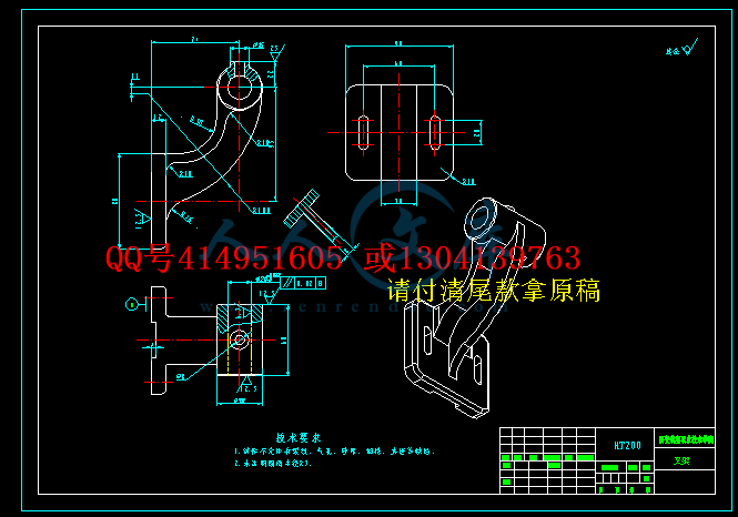
题目给出的零件是叉架。它在车辆上面应用范围很广。该类零件的结构和尺寸有着很大的差异,但结构上仍有共同特点:零件的主要表面为精度要求较高的孔、零件由内孔、外圆、端面等表面构成。因此叉架零件的加工质量,不但直接影响的装配精度和运动精度,而且还会影响工作精度、使用性能和寿命。叉架零件的底面用以安装盖,实现功能。
1.1.2 零件的工艺分析
由叉架零件图可知。分析如下:
1.以80×90的平面C为设计基准的加工表面
这组加工表面包括:Φ38的两个端面粗糙度Ra12.5,以及直径为Φ20孔粗糙度要求为Ra2.3,以及相距60mm的两槽粗糙度要求为Ra12.5
2. Φ20孔为基准加工表面


 川公网安备: 51019002004831号