预锻模.dwg
预锻模.dwg

高压阀盖的锻模模具设计及成型工艺有限元模拟仿真【优秀带14张CAD图纸】

收藏

资源目录
跳过导航链接。
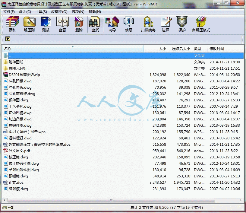
高压阀盖的锻模模具设计及成型工艺有限元模拟仿真【优秀带14张CAD图纸】.rar
预锻模.dwg---(点击预览)
锻件图.dwg---(点击预览)
退料螺钉.dwg---(点击预览)
终锻模.dwg---(点击预览)
热锻件图.dwg---(点击预览)
正文.doc---(点击预览)
校正热锻件图.dwg---(点击预览)
校正模.dwg---(点击预览)
工艺卡片.dwg---(点击预览)
实习(调研)报告.wps---(点击预览)
外文翻译译文:锻造技术的新发展.doc---(点击预览)
外文原文.pdf---(点击预览)
切边凹模.dwg---(点击预览)
切边凸模.dwg---(点击预览)
冲孔落料板.dwg---(点击预览)
冲孔凹模.dwg---(点击预览)
冲孔冲头.dwg---(点击预览)
予锻热锻件图.dwg---(点击预览)
有限元分析
附件图纸
DF201阀盖图纸.zip
压缩包内文档预览:
预览图
编号:366090    类型:共享资源    大小:11.61MB    格式:RAR    上传时间:2014-11-21 上传人:QQ14****9609 IP属地:陕西
40
积分
关 键 词:
高压阀盖 锻模 模具设计 成型工艺 有限元 模拟仿真
资源描述:

高压阀盖的锻模模具设计及成型工艺有限元模拟仿真【优秀带14张CAD图纸】

【带外文翻译+实习(调研)报告+36页@正文15700字】【详情如下】【需要咨询购买全套设计请加QQ1459919609 】.bat

DF201阀盖图纸.zip

予锻热锻件图.dwg

冲孔冲头.dwg

冲孔凹模.dwg

冲孔落料板.dwg

切边凸模.dwg

切边凹模.dwg

外文原文.pdf

外文翻译译文:锻造技术的新发展.doc

实习(调研)报告.wps

工艺卡片.dwg

有限元分析

校正模.dwg

校正热锻件图.dwg

正文.doc

热锻件图.dwg

终锻模.dwg

退料螺钉.dwg

锻件图.dwg

附件图纸

预锻模.dwg

摘  要

高压阀盖是一个中心对称的柄类与轴类锻件,调节阀门与气动调节阀的重要组成部分。它是一种难度系数介于常见盘类和轴类之间的锻件。普遍存在的质量缺陷如:折叠,充不满,密封不好,精度低等成为了制约我国精锻技术的发展和普及的主要因素。多数企业的技术人员仍是以一些成熟的经验作为设计准则,试模周期较长,成本较高,耗能较大,而且不能综合考虑成形缺陷形成的各个因素,造成设计结果与实际情况相差甚远,从而给企业带来了严重的经济损失。本文以大连大锻有限公司生产的某高压阀盖为研究对象,经过深入研究该锻件原始工艺方案的成形缺陷,利用分流原理提出了分流工艺方案,制定了预终锻锻件图,设计了模具结构,利用 DEFORM-3D 软件建立了有限元模型对原始对预锻和终锻方案过程进行数值模拟,分析了制坯,预锻,终锻的优缺点。对整个生产过程,做了一个比较系统的分析。通过与实际生产的对比,验证了工艺方案的可行性。通过本课题的研究,把高压阀盖制坯到预锻,终锻成形过程与塑性有限元技术、数值模拟仿真分析技术有效的结合,发现高压阀盖实际生产中的边角充不满,较大的飞边问题等缺陷,并提出解决方案。解决了实际生产问题。

关键词:高压阀盖 模锻 有限元数值模拟 仿真

ABSTRACT

  High-pressure valve cover is a central symmetrical pattern classes and shaft forgings, an

important part of regulating valves and pneumatic control valve. It is a common difficulty

coefficient between the disc type and shaft forgings between. Common quality defects such as: folding, fully satisfied, sealing well, low accuracy has become a major factor restricting the development of technology and the popularity of forging. Most companies are still a number of technical personnel mature experience as a design criterion, tryout period is longer, higher costs, greater energy, and can not be taken into account various factors shaping defect formation, resulting in the design and actual results vary considerably far, giving enterprises a serious economic losses. Taking a high-pressure valve forging Co., Ltd. Dalian cover for the study, in-depth study of the forging forming defects original process plan, the use of the principle of triage triage process scheme is proposed to develop a pre-final forging forging figure, the mold structure design using DEFORM-3D software to build a finite element model of the original pre-forging and final forging process simulation program to analyze the blank, pre-forging, the final forging advantages and disadvantages. The entire production process, made a more systematic analysis. By comparison with the actual production process to verify the feasibility of the program. By studying this subject, the high-pressure valve cap system to pre-forging billet, forging process and the final plastic finite element techniques, effective analysis and numerical simulation techniques, found that the actual production of the high-pressure valve cover corners fully satisfied, the larger defects such as burr problem and propose solutions. Solve the problem of the actual production.

Key words:High-pressure valve cover   forging  finite element simulation

目  录

第一章  绪论1

1.1 锻造业的地位及其发展方向1

1.2 设计题目及其设计要求1

1.2.1设计题目1

1.3  设计任务及要求1

1.4  技术经济可行性分析2

1.5 小结3

第二章 锻件图的制定4

2.1 冷锻件图的制定4

2.1.1 分模面位置的选择4

2.1.2 锻件机械加工余量和公差4

2.1.3 模锻斜度5

2.1.4 圆角半径6

2.1.5 锻件的热处理和清理6

2.2小结6

第三章 成型工艺仿真8

3.1概述8

3.2  模拟技术在锻造工艺实践中的重要作用和地位8

3.3  UG平台下高压阀盖的特征造型及其模具造型9

3.4  DEFORM模拟仿真10

3.4.1  前处理器10

3.4.2 模拟处理器10

3.4.3  后处理器11

3.5   Deform软件操作流程概述11

3.6 小结16

第四章 模锻工步的选择17

4.1 计算毛坯17

4.1.1 飞边槽的设计17

4.1.2 绘制和计算毛坯的截面图和直径图18

4.2 确定锻造工步20

4.3 坯料截面计算20

4.4 坯料长度的计算20

4.5 确定设备吨位21

4.6 锻模结构设计21

4.6.1 模膛布置21

4.7锻模模具设计23

4.7.1确定热锻件23

4.8 模膛壁厚的确定24

4.8.1模块的确定25

4.9 小结25

第五章  切边模的设计26

5.1小结27

第六章  校正模的设计28

6.1 小结29

谢辞30

参考文献31

第一章 绪论

1.1 锻造业的地位及其发展方向

  锻造是一种利用锻压机械对金属坯料施加压力,使其产生塑性变形以获得具有一定机械性能、一定形状和尺寸锻件的加工方法,锻压(锻造与冲压)的两大组成部分之一。通过锻造能消除金属在冶炼过程中产生的铸态疏松等缺陷,优化微观组织结构,同时由于保存了完整的金属流线,锻件的机械性能一般优于同样材料的铸件。相关机械中负载高、工作条件严峻的重要零件,除形状较简单的可用轧制的板材、型材或焊接件外,多采用锻件。该方法可追溯到公元前40 世纪自然金属如金、银的成形。在现代工业的今天, 展现在我们眼前的是全自动高速锻造生产线。最为典型的可举出曲轴、连杆热锻生产线, 齿轮、十字头的冷锻生产线以及以紧固件为代表的高速冷锻机成形。从“趁热打铁”可以自然的想到锻造是在高温下进行的。自1938 年德国发明了磷化皂化技术以来, 冷锻技术得到了广泛的应用。二战期间的德国, 为了以钢材代替铜来生产弹壳等军工产品, 发明了既具有附着性又兼备高延展性的磷化皂化皮膜。二战结束以后, 此技术先传到美国, 进而很快普及到全世界。60 年代以后, 汽车的大量生产又为冷锻技术的发展创造了广阔的天地[3]。

   锻造可分为自由锻、镦粗、挤压、模锻、闭式模锻、闭式镦锻。自由锻。利用冲击力或压力使金属在上下两个抵铁(砧块)间产生变形以获得所需锻件,主要有手工锻造和机械锻造两种。模锻。模锻又分为开式模锻和闭式模锻.金属坯料在具有一定形状的锻模膛内受压变形而获得锻件,又可分为冷镦、辊锻、径向锻造和挤压等等。闭式模锻和闭式镦锻由于没有飞边,材料的利用率就高。用一道工序或几道工序就可能完成复杂锻件的精加工。由于没有飞边,锻件的受力面积就减少,所需要的荷载也减少。但是,应注意不能使坯料完全受到限制,为此要严格控制坯料的体积,控制锻模的相对位置和对锻件进行测量,努力减少锻模的磨损[2]。

1.2设计题目及其设计要求

1.2.1设计题目:

  高压阀盖锻模设计及其成形数值模拟

1.3 设计任务及要求  

   1.设计(研究)内容和要求(包括设计或研究内容、主要指标与技术参数,并根据课题性质对学生提出具体要求) 

(1)实习调研,翻译外文资料

1、实习调研,查阅文献15篇以上;

2、翻译不少于5000汉字的外文资料,要求外文文献与锻模设计相关;

3、查阅基于Deform的模拟锻造成形的相关论文;

4、查阅并整理锻模设计方面的文献。

(2)模具总体方案设计

    1、根据任务书,结合实际,制定高压阀盖锻件生产工艺方案;2、设计锻模。

(3)模具设计  

1、根据零件图制定锻件图,并计算毛坯,制定锻造工步,方案合理;

    2、结合有限元模拟结果,应用CAD软件进行模具各零件和模具装配图的设计;

    3、绘制模具总装配图及主要部件的零件图。要求设计并绘制完成2副模具的装配图、主要模具零件的零件图,图纸量2.5-3张A0,符合国标,模具要简单实用。

(4)设计说明书编写

参 考 文 献

[1] 李硕本,冲压工艺学,北京,机械工业出版社,1982.1;

[2] 李佑天,冲压工艺手册(修订本),长沙,湖南科学技术出版社,1984;

[3] 胡世光,板料冷压成形原理,北京,国防工业出版社,1990;

[4] 吴诗惇,冲压工艺学[M],西安,西北工业大学出版社,1987.6;

[5]史铁梁,模具设计指导[M],北京,机械工业出版社,2003.8;

[6]万战胜,冲压模具设计[M],北京,中国铁道出版社,1988;

[7] 李双义,冷冲模具设计[M],北京,清华大学出版社,2002.2;

[8] 湖南机械工程学会锻压分会,冲压工艺,长沙,湖南科学技术出版社,1984;

[9]梁炳文, 实用板金冲压工艺图(第一集)第1版,北京:机械工业出社,1991;

[10] 李志刚,模具CAD/CAM[M],北京,机械工业出版业,1995;

[11] 丁松聚,冷冲压设计,北京,机械工业出版社,1994.7;

[12] 王孝培,冲压手册[K],北京,机械工业出版社,1988.2;

[13] 王孝培,实用冲压技术手册[M],北京,机械工业出版社,2001;

[14] 《冲模设计手册》编写组,冲模设计手册[M],北京,机械工业出版社,1999;

[15] 肖景容,冲压工艺学[M],北京,机械工业出版社,2000.5;

[16] 李彦蓉、杜言利、肖作义,镶拼式冲模设计,模具技术[J],2000(3), 41-43;

[17] 第四机械工业部标准化研究所编,冷压冲模结构图册[M],北京,1981;

[18] 侯洪生,机械工程图学[M],北京,科学出版社,2005.1;

[19] 陈榕林,常用机械设计新旧标准对照手册[M],北京,中国建材工业出版社1992.11;

[21] 田嘉生,冲模设计基础[M],北京,航空工业出版社,1994.9;

[22] 模具制造编写组,模具制造手册[M],北京,机械工业出版社,1982;

[23] 冯炳尧等,模具设计与制造简明手册[M],上海,上海科学技术出版社,1983;

[24] 黄毅宏,模具制造工艺[M],北京,机械工业出版社,1988.6;

[25] 张春水,高效精密冲模设计与制造[M],西安,西安电子科技大学出版社,l990;

[26] 张钧,冷冲压模具设计与制造[M],西安,西北工业大学出版杜,1993;

[27] 肖景荣,模具计算机辅助设计与制造[M],北京,国防工业出版社,1990;


内容简介:
New Trends in Forging Technologies B.-A. Behrensa, T. Hagena, J. Kniggea, I. Elgalya, T. Hadifia, A. Bouguechaa aInstitute of Metal Forming and Metal-Forming Machines, Leibniz Universitt Hannover, An der Universitt 2, 30823 Garbsen, Germany Abstract. Limited natural resources increase the demand on highly efficient machinery and transportation means. New energy-saving mobility concepts call for design optimisation through downsizing of components and choice of corrosion resistant materials possessing high strength to density ratios. Component downsizing can be performed either by constructive structural optimisation or by substituting heavy materials with lighter high-strength ones. In this context, forging plays an important role in manufacturing load-optimised structural components. At the Institute of Metal Forming and Metal-Forming Machines (IFUM) various innovative forging technologies have been developed. With regard to structural optimisation, different strategies for localised reinforcement of components were investigated. Locally induced strain hardening by means of cold forging under a superimposed hydrostatic pressure could be realised. In addition, controlled martensitic zones could be created through forming induced phase conversion in metastable austenitic steels. Other research focused on the replacement of heavy steel parts with high-strength nonferrous alloys or hybrid material compounds. Several forging processes of magnesium, aluminium and titanium alloys for different aeronautical and automotive applications were developed. The whole process chain from material characterisation via simulation-based process design to the production of the parts has been considered. The feasibility of forging complex shaped geometries using these alloys was confirmed. In spite of the difficulties encountered due to machine noise and high temperature, acoustic emission (AE) technique has been successfully applied for online monitoring of forging defects. New AE analysis algorithm has been developed, so that different signal patterns due to various events such as product/die cracking or die wear could be detected and classified. Further, the feasibility of the mentioned forging technologies was proven by means of the finite element analysis (FEA). For example, the integrity of forging dies with respect to crack initiation due to thermo-mechanical fatigue as well as the ductile damage of forgings was investigated with the help of cumulative damage models. In this paper some of the mentioned approaches are described. Keywords: Acoustic emission, Cold forging, Damage models, Downsizing, Heatless hardening, Online monitoring, Superimposed hydrostatic pressure, Transformation induced plasticity PACS: 02.70.Dh; 81.20.Hy; 83.50.Uv; 62.20.M-; 62.20.fq; 62.20.me, 64.60.My INTRODUCTION In order to meet rising technical and social demands in times of scarce fossil energy and rising environmental regulations, the use of light metals and load-adapted structure concepts increases in most domains of mechanical engineering. The automotive industry as well as the aircraft industry as one of the first users of downsized and weight reduced components have great interest in the development of innovative materials and process technologies. Since the introduction of high strength and/or light weight non-ferrous metals in modern production engineering, the group of metal forming techniques is facing great challenges. The common production processes are often not suitable to utilise the full potential which these materials may offer. As a result, continuous attempts to improve the characteristics, processing properties and combinations of materials are carried out. This paper presents some of the new trends in forging processes of metastable austenitic steels and non-ferrous wrought alloys on the material side. Regarding new numerical computation techniques, some approaches of the numerical prediction of ductile damage in hot forging dies due to thermo-mechanical fatigue and the evolution of the microstructure in forming processes are introduced. Furthermore, considering process monitoring acoustic emission sensor systems can be a powerful tool to detect damage or crack occurrence online the forming operation. The 14th International ESAFORM Conference on Material FormingAIP Conf. Proc. 1353, 380-385 (2011); doi: 10.1063/1.3589545 2011 American Institute of Physics 978-0-7354-0911-8/$30.00380ADAPTED MARTENSITIC AREAS DUE TO FORMING-INDUCED PHASE TRANSFORMATION IN METASTABLE AUSTENITIC STEELS During the cold forging of metastable austenitic steels, transformation-induced martensite can occur. This leads to an increase in flow stress and strength and offers new design possibilities for light-weight and/or crash components. One research objective is to enable this effect of transformation-induced martensite in metastable austenitic steels by the forging process 1. In detail, by adjusting forging parameters such as true plastic strains, strain rate and forging temperature, locally strengthened areas in solid components were created. The dependence of the martensite content in the experiments on the forging parameters was analysed on the basis of upsetting tests. Various chrome nickel steels and one manganese hard steel were examined regarding transformation-induced martensite formation under compressive stresses. The quantification of the martensite evolution was carried out by means of a Feritscope and a Magnatest. Then, the results were approved by metallographic and numeric analyses. Based on test series with a constant strain rate of = 0.1 s-1 and varying forging temperatures of TF = -5, 20 and 60 C, a significant influence of the forging temperature on the martensite content was detected. Due to cooling the specimens to TF = -5 C, an immense increase in the martensite evolution is activated compared to those experiments taken at room temperature. On the other side, increasing the forging temperature reduces the effect of the martensitic phase conversion. At a temperature of TF = 60 C, a phase conversion is close to be completely suppressed. Besides, a distinct strain rate dependency of the martensite content was determined. This is the result of an increased adiabatic heating during the upsetting tests at high strain rates, which also suppresses phase transformation due to increased inner temperature. FORGING UNDER SUPERIMPOSED HYDROSTATIC PRESSURE Forming under superimposed media-based hydrostatic pressure is a promising approach to handling low ductile steels and non-ferrous metals in a forming process. The influence of superimposed hydrostatic pressure on the flow stress as well as on the formability for various hydrostatic pressures, forming temperatures and aluminium and magnesium alloys was analysed 2, 3. By increasing the formability of the workpieces, larger local plastic strains could be achieved. Considering aluminium wrought alloys, in upsetting tests under superimposed pressure of 85 MPa the formability of workpieces from thermosetting alloy AlSi1MgMn (AW-6082) was more increased compared to those from self-hardening alloy AlMg4.5Mn0.7 (AW-5083). As a general tendency, the self-hardening alloys show a lower increase in formability when forged under superimposed pressure. To determine the process limits considering highest increase in formability and complexity of workpiece geometry a new tool-concept (see Figure 1, left) was designed for applicably superimposing pressures up to max. 200 MPa. EjectorClosing plateDieRamDie insertsSealingsLoad cellGuide frame UpsettingLateral ExtrusionDuctsTopdie insertBottomdie insertWork piece FIGURE 1. left: Tool-concept for superimposed pressures of max. 200 MPa, right: Die inserts for upsetting and lateral extrusion processes The tool design uses a closing plate, an ejector and easily changeable die inserts (see Figure 1, right). Hereby, various forging methods such as upsetting and extrusion processes can be carried out. The hydraulic pressure is 381provided by an active hydraulic power unit and controlled by cascading chokes of specified diameters during the forming operation. By using the formability increase the raw part geometries can be selectively varied to forms which can not be forged in a conventional forging process. By forming these selected preforms under superimposed hydrostatic pressure locally adapted strain hardening can be induced. ACOUSTIC EMISSION ANALYSIS - A NEW FACILITY FOR ONLINE MONITORING OF FORGING PROCESSES Through this work, three main subjects have been studied: the feasibility of applying acoustic emission technique to forging processes, determination of suitable parameter sets for signal acquisition under harsh industrial working conditions, and finally, comparison of possible AE signal analysis methods that can be applied in order to reach a conclusion about the quality of the manufactured component or the condition of the forging die 4. The main part of investigation was performed using a high-end professional AE system (AMSY-5, Vallen Systeme, Germany). The 8-channels system is capable of 10 MS/s sampling rate per channel, and is equipped with different types of resonant and broadband sensors, various filters and transient recorder for real time acquisition. The use of broadband sensors up to 2.4 MHz and the application of both hardware filters (400-1600 kHz) as well as energy and duration-based criteria (e.g. E 50x109 V2s & 20 s D 1 ms) made it possible to cut off nearly all encountered machine noise. The test specimens were machined out of extruded bars made of AZ31 and AZ80 magnesium alloys in addition to the widely used aluminium forging alloy (AW-6082). At first, numerous upsetting tests were performed to examine different acquisition parameters and filter settings. Optimal combination of acquisition parameters, filter range as well as auxiliary filtering criteria (e.g. energy level) has been determined for both threshold-based and continuous signal acquisition. Further upsetting tests were performed in order to investigate the influence of material type, specimen geometry, test temperature and strain rate on the generation of AE 5. With the aid of AE analysis, it was possible to detect cracking signals at different strains according to the specimens geometry as well as the applied strain rate and test temperature. Moreover, the analysis of upsetting experiments confirmed the proportionality of AE energy to the strain rate, especially in the elastic-plastic transition zone, as reported for other types of materials 6. In order to develop an online-capable inspection system, a more detailed analysis of the recorded AE patterns was necessary. Examination of signal forms in time domain and their corresponding spectra in frequency domain showed that characteristic AE patterns can be correlated with definite typical events and defects encountered during the forging operations. The main pattern types that could be correlated with physical events are cracking-elated patterns, yield-related patterns, plastic-deformation-related patterns as well as friction-related patterns. However, the computational cost of the statistical correlation and classification methods (e.g. PCA) as well as other Time-Frequency-Representation (TFR) methods, e.g. Gabor or Wavelet transforms, is too high and practically not applicable in case of online monitoring. Therefore, a new indicator based on combined temporal and spectral parameters has been developed within the scope of this work. The new Pattern Indicator For Forging (AE-PIFF) considers the main attributes that characterise the encountered AE patterns which are related to predefined defects or events in both time and frequency domain. Due to its structure, the AE-PIFF possesses a lower computational cost when compared to other statistical correlation or TFR methods. This advantage makes it appropriate for online monitoring and quality control purposes. Validation of this indicator on a variety of materials and test conditions will facilitate the integration of AE technique into the mainstream of industrial forging processes. Further improvement of the AE-PIFF parameter is required in order to be more efficient and flexible in determining more types of patterns. The validity of the indicator should be also examined on more materials and under different test conditions. AE-PIFF maps can be also established to represent diverse cases. DUCTILE DAMAGE PREDICTION IN HOT FORGING DIES DUE TO THERMO-MECHANICAL FATIGUE Due to high temperatures and forming forces, which arise in forging processes, forging dies undergo high thermal and mechanical loads. These loads have a major impact on the fatigue life of the shaping tools and thus can lead to fatigue crack initiation on the die surface. Tool failure due to thermo-mechanical fatigue represents along with abrasive wear the most frequent cause for forging tool failure 7. Fatigue cracks arise in areas which are subjected to cyclic plastic deformation caused by excessive mechanical loads. Plastic deformations combined with thermal cycling on the die surface lead to material fatigue. This material fatigue predominantly leads to a decrease in strength which can provoke a fatigue crack initiation. According to the theory of elastic-plastic fracture mechanics a 382crack initiation is followed by crack growth and fracture. A low tool life quantity of less than 10,000 cycles as well as a crack initiation in a die cavity radius is a clear sign for a low cycle fatigue failure. In this case the occurring strain amplitude comprises an elastic and a plastic part which determines the crack initiation life within the low cycle fatigue area 8. An industrial forging process was analysed, where the lower dies failed due to fatigue crack initiation. This forging process is used to produce an U-joint yoke screw connection a three-stage forming operation. As can be seen in Figure 2, left, the fatigue crack initiation in the lower die occurs in the die cavity radius, which can be ascribed to the high operational loads in that area. The maximum loads appear in the last stage of the forming process as full form filling is at hand. In this stage the upper die travels towards the workpiece at a speed of 1200 mm/s and induces high hydrostatic and shear stresses in the die cavities due to the form filling of the lower die. The upper die which is irrelevant for the fatigue crack analysis has been assumed to be rigid within the FE simulation. FIGURE 2. left: Lower die with fatigue crack in the cavity radius, right: Distribution of the Oyane cumulative damage parameter in the lower die at the end of the third forming stage The material behaviour of the hot work tool steel has been described with the help of a material model according to the Norton-Hoff formulation 9 for conditions typical for hot forging. This material law calculates the local material flow stress depending on the true strain, the strain rate and the temperature in the material. Appropriate material model parameters for the hot work tool EN 1.2367 steel have been taken according to literature 10. The FEA based damage analysis of the lower die has been done with the help of the process related loads and the cumulative damage parameter according to Oyane 11. This model is capable of computing the damage in mechanical components based on the stress and strain history during service. The Oyane damage criterion calculates the mechanical damage by means of integration over the plastic strain of a function which depends on the current stress state, and expresses the stress function based on a ratio of the hydrostatic stress to the v. Mises equivalent stress. The distributions of the qualitative damage (Figure 2, right) reveal that the fatigue crack location exhibits the maximum tool steel damage. FINITE-ELEMENT-ANALYSIS OF THE MICROSTRUCTURE EVOLUTION IN FORMING PROCESSES The prediction of residual stresses and shape distortion geometrical changes in forged parts with the help of numerical simulation during the process design is of high economical and technical relevance. This may lead to a reduction of the numerous tests for the design and optimisation of heat treatment and forging processes. The fundamental causes for shape distortion in forged parts are according to 12 due to non-thermal volumetric changes and plastic deformations. The former cause is induced by volumetric changes in the material due to microstructural changes during the heat treatment process. Local plastic deformations in forged parts may arise, when the residual stresses exceed the specific yield strength of the material. Current commercial FEA systems are not able to predict the microstructure evolution and the resulting residual stresses and geometrical changes in warm and hot forged parts in a realistic manner. In order to consider the phase 383changes in FEA of forging processes an extended material model was implemented into the commercial FE code Msc.Marc 2007r1. The model for phase transformation is described in 13 in detail. For the modelling of the thermal-elastic-plastic-metallurgic behaviour, the strain increment dij can be described by the sum of the elastic (el), plastic (pl), thermal (th), isotropic transformation (tr), and transformation-induced plasticity (tp) strains by elplthtrtpddd+dddijijijijijij=+ . (1) The modelling of the isotropic transformation and transformation-induced plasticity strains due to phase transformations is explained below. Isotropic Transformation Strains Due to the different lattice structures of austenite (fcc) and the resulting microstructures ferrite, pearlite, bainite (bcc) and martensite (bct), a volume change occurs during the phase transformation. This phenomenon can be ascribed to the isotropic transformation strains. The consideration of these is done by adding the isotropic transformation strains and the thermal strains via ()()nth+trthtrnd dd1ttttijijijijttaTaT+=+= (2) as a function of the averaged lattice constants an at the start and end of a time step t. The averaged lattice constants are a function of the Temperature T and can be determined by the microstructure fractions and the lattice constants of the individual phases. Transformation-induced Plasticity Strains Due to changes in volume and shape of the crystals during the phase transformation, the softer phase has to adapt to the environment of the harder phase. This leads to complicated residual stress conditions causing plastic yielding, even if the stresses are smaller than the yield stress of the material. External stresses either initiate or amplify the effect. The transformation-induced plasticity strain increment can be described by the model according to Leblond, cf. 14, via ()4tptpvM=1y,y,y,d3d 3hdlnd2ijijijkkkkssVV,= (3) The factor sij represents the deviatoric stress tensor and the phase fraction of the product phase k is k. Furthermore, the yield stress of austenite is y, and the equivalent stress according to von Mises is vM. The factor (dV/V),k describes the volume change due to a phase transformation from austenite to the product phase k. Because more than one new phase can develop within one time step, summing is done over all product phases k. The correction function h has been taken according to 14. Validation of the Material Model The presented approach for the consideration of the phase transformations in the stress computation was validated by dilatometer tests. This was done using the manganese-boron steel 22MnB5 (1.5528) as an example. The experimental results are taken from the investigations of Somani et al. 15. In Figure 3, the basic simulation model is presented on the right. The austenitisation temperature is 900C, and the specimen is quenched with a cooling rate of dT/dt = 50C/s. Three load cases are examined with a varying pressure p (p = 165 N/mm2, p = 0 N/mm2 and p = 112 N/mm2). A comparison of the measured and the computed diameter change d/d0 is shown in Figure 3 on the left. It is obvious that with a load of p = 0 N/mm2 the simulation and the experiment match well. Because only thermal and isotropic transformation strains occur in this case, the approach for the isotropic transformation strains is thus validated. By means of the applied tensile or compression stress, the approach for the transformation-induced plasticity is validated. The difference shortly before the start of transformation at T = 400C can be partly explained by the unknown force distribution in the sample during the experiment. Nonetheless, it can also be said that the simulation and the experiment match well in these cases. 384 FIGURE 3. Simulation model of a dilatometer test and comparison of measured and computed diameter changes ACKNOWLEDGMENTS The authors gratefully acknowledge the financial support of the Collective Research for Small and Medium-sized Enterprises research plan IGF AiF 15640 N with the lemma “Rissbildungssimulation” by the German Federation of Industrial Research Associations. A special thank is to the Hirschvogel Umformtechnik GmbH company for providing the industrial forging process. The authors would also like to thank the German research foundation (DFG) for funding the Collaborative Research Center 675 (SFB 675) - Creation of high strength metallic structures and joints by setting up scaled local material properties. REFERENCES 1. B.-A. Behrens; K. Voges-Schwieger; A. Bouguecha; J. Knigge; K. Weilandt; S. Hbner: Local Strain Hardening of Metal Components by Means of Martensite Generation, Advanced Materials Research Vol. 137, 2010, pp. 1-33, Trans Tech Publications, Switzerland 2. B.-A. Behrens; T. Hagen; A. Klassen; J. Knigge; J. Mielke; I. Pfeiffer: Forging of Aluminium Components under a Superimposed Hydrostatic Pressure to Induce Local Strain Hardening, Advanced Materials Research Vol. 137 (2010) pp 191-217, 2010 Trans Tech Publications, Switzerland 3. I. El Galy; I. Pfeiffer; B.-A. Behrens: Application of Acoustic Emission to Monitor Forging Processes of Magnesium Alloys under Superimposed Hydrost
温馨提示:
1: 本站所有资源如无特殊说明,都需要本地电脑安装OFFICE2007和PDF阅读器。图纸软件为CAD,CAXA,PROE,UG,SolidWorks等.压缩文件请下载最新的WinRAR软件解压。
2: 本站的文档不包含任何第三方提供的附件图纸等,如果需要附件,请联系上传者。文件的所有权益归上传用户所有。
3.本站RAR压缩包中若带图纸,网页内容里面会有图纸预览,若没有图纸预览就没有图纸。
4. 未经权益所有人同意不得将文件中的内容挪作商业或盈利用途。
5. 人人文库网仅提供信息存储空间,仅对用户上传内容的表现方式做保护处理,对用户上传分享的文档内容本身不做任何修改或编辑,并不能对任何下载内容负责。
6. 下载文件中如有侵权或不适当内容,请与我们联系,我们立即纠正。
7. 本站不保证下载资源的准确性、安全性和完整性, 同时也不承担用户因使用这些下载资源对自己和他人造成任何形式的伤害或损失。
提示  人人文库网所有资源均是用户自行上传分享,仅供网友学习交流,未经上传用户书面授权,请勿作他用。
关于本文
本文标题:高压阀盖的锻模模具设计及成型工艺有限元模拟仿真【优秀带14张CAD图纸】
链接地址:https://www.renrendoc.com/p-366090.html

官方联系方式

2:不支持迅雷下载,请使用浏览器下载   
3:不支持QQ浏览器下载,请用其他浏览器   
4:下载后的文档和图纸-无水印   
5:文档经过压缩,下载后原文更清晰   
关于我们 - 网站声明 - 网站地图 - 资源地图 - 友情链接 - 网站客服 - 联系我们

网站客服QQ:2881952447     

copyright@ 2020-2025  renrendoc.com 人人文库版权所有   联系电话:400-852-1180

备案号:蜀ICP备2022000484号-2       经营许可证: 川B2-20220663       公网安备川公网安备: 51019002004831号

本站为文档C2C交易模式,即用户上传的文档直接被用户下载,本站只是中间服务平台,本站所有文档下载所得的收益归上传人(含作者)所有。人人文库网仅提供信息存储空间,仅对用户上传内容的表现方式做保护处理,对上载内容本身不做任何修改或编辑。若文档所含内容侵犯了您的版权或隐私,请立即通知人人文库网,我们立即给予删除!