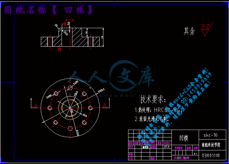
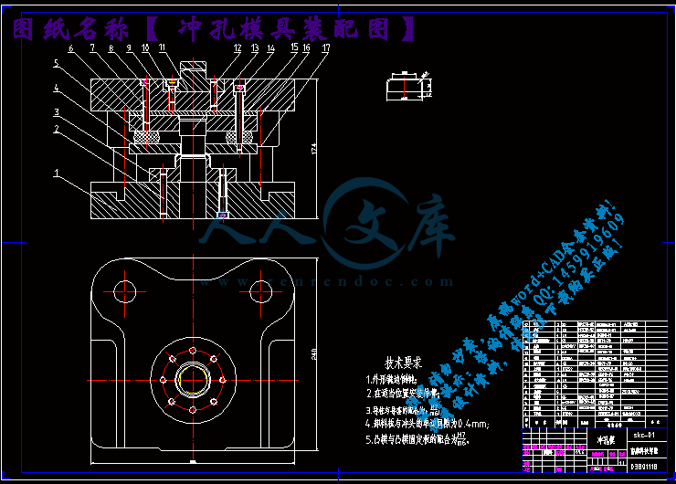
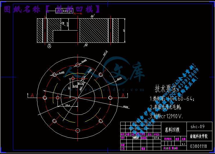
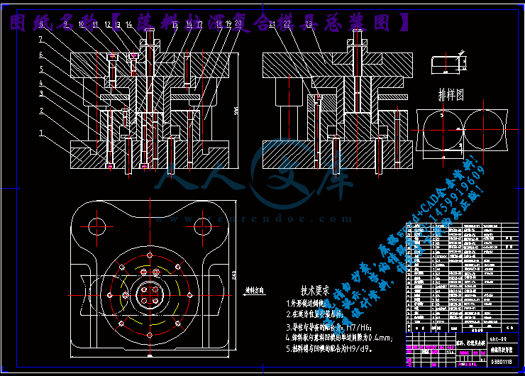
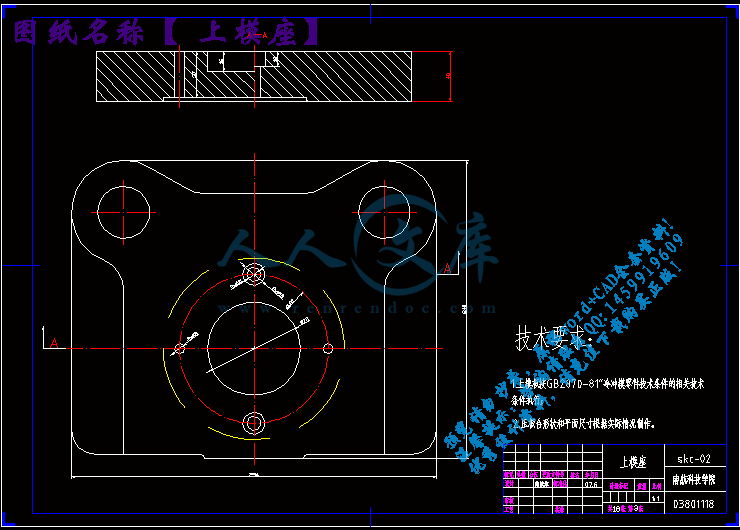
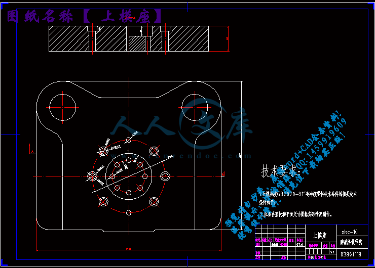
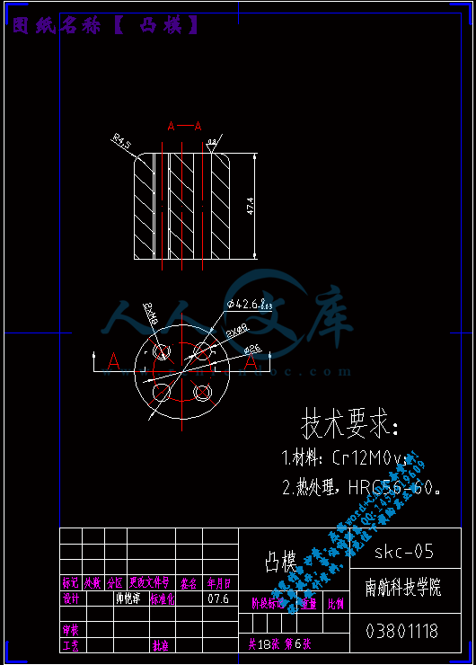
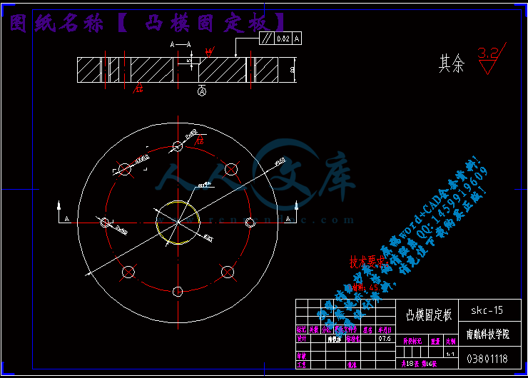
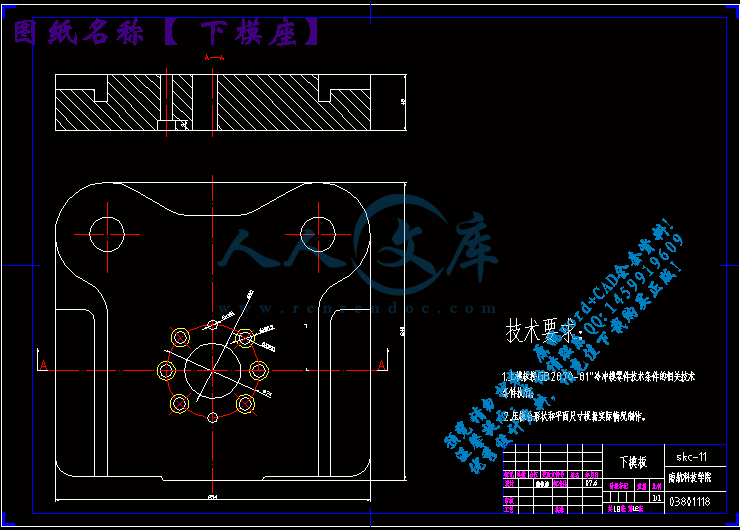
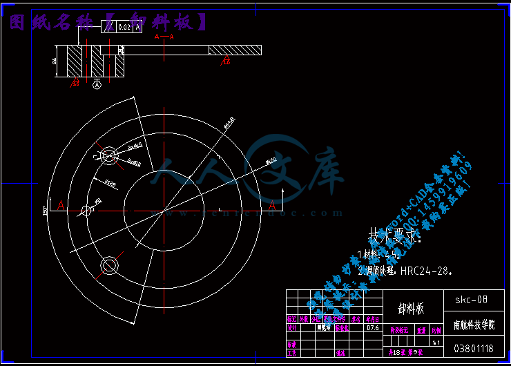
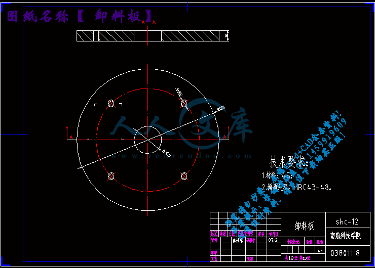
零件图.dwg
零件图.dwg

筒形件的落料、拉深复合模及单工序冲孔模具设计【优秀冲压复合模设计+18张CAD图纸】

收藏

资源目录
跳过导航链接。
筒形件的落料、拉伸复合模及单工序冲孔模具设计【优秀+18张CAD图纸】.rar
零件图.dwg---(点击预览)
落料拉深复合模具总装图.dwg---(点击预览)
落料凹模.dwg---(点击预览)
英文摘要.doc---(点击预览)
翻译.doc---(点击预览)
筒形件的落料、拉伸复合模及单工序冲孔模具设计正文.doc---(点击预览)
目录.doc---(点击预览)
正文.doc---(点击预览)
推件器.dwg---(点击预览)
拉深凹模.dwg---(点击预览)
开题报告.doc---(点击预览)
复合模具打印图纸总汇17张.dwg---(点击预览)
垫板.dwg---(点击预览)
压料板.dwg---(点击预览)
卸料板.dwg---(点击预览)
凹模.dwg---(点击预览)
凸模固定板.dwg---(点击预览)
凸模.dwg---(点击预览)
冲孔模具装配图.dwg---(点击预览)
冲孔模具卸料板 .dwg---(点击预览)
冲孔模具下模座 .dwg---(点击预览)
冲孔模具上模座 .dwg---(点击预览)
冲头.dwg---(点击预览)
任务书.doc---(点击预览)
中文摘要.doc---(点击预览)
下模座.dwg---(点击预览)
上模座.dwg---(点击预览)
Stamping formability of pure titanium sheets.pdf---(点击预览)
Recent developments in sheet hydroforming technology.pdf---(点击预览)
第1套落料拉深复合模具
第2套冲孔模具
压缩包内文档预览:
预览图
编号:369474    类型:共享资源    大小:3.05MB    格式:RAR    上传时间:2014-12-06 上传人:QQ14****9609 IP属地:陕西
45
积分
关 键 词:
筒形件 拉伸模 复合模具 冲孔模具设计 筒形件的落料、拉深复合模 单工序冲孔模具设计
资源描述:

筒形件的落料、拉伸复合模及单工序冲孔模具设计【优秀冲压复合模设计+18张CAD图纸】

筒形件的落料、拉伸、冲孔复合模具设计

筒形件的冲压复合模具设计

电器开关网芯零件的落料、拉伸复合模及单工序冲孔模具设计

电器开关网芯的冲压工艺规程及模具设计

电器开关网芯的冲压工艺及模具设计

单工序冲孔模具设计

落料、拉伸复合模及单工序冲孔模具的设计

筒形件的落料、拉伸复合模及单工序冲孔模具设计【优秀冲压复合模设计+18张CAD图纸】

【带2套模具+任务书+开题报告+外文翻译+32页@正文11800字】【详情如下】【需要咨询购买全套设计请加QQ1459919609 】.bat

Recent developments in sheet hydroforming technology.pdf

Stamping formability of pure titanium sheets.pdf

上模座.dwg

下模座.dwg

中文摘要.doc

任务书.doc

冲头.dwg

冲孔模具上模座 .dwg

冲孔模具下模座 .dwg

冲孔模具卸料板 .dwg

冲孔模具装配图.dwg

凸模.dwg

凸模固定板.dwg

凹模.dwg

卸料板.dwg

压料板.dwg

垫板.dwg

复合模具打印图纸总汇17张.dwg

开题报告.doc

拉深凹模.dwg

推件器.dwg

目录.doc

第1套落料拉深复合模具

第2套冲孔模具

翻译.doc

英文摘要.doc

落料凹模.dwg

落料拉深复合模具总装图.dwg

论文.doc

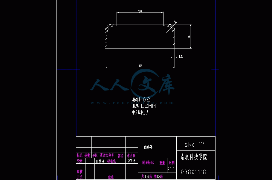
零件图.dwg

南 昌 航 空 大 学 科 技 学 院

毕业设计(论文)任务书

I、毕业设计(论文)题目:

筒形件零件冲压工艺及模具设计

II、毕业设计(论文)使用的原始资料(数据)及设计技术要求:

一.原始资料:

(1)筒形件零件图 1张,零件大批量生产

(2)冷冲模标准 1套        

二.技术要求:

(1)设计出的冲压模具能保证有正确的板料定位和冲压顺序动作、送料和取件方便;模具结构

紧凑;装配关系准确。

(2)设计出的模具零件图尺寸齐全、加工要求和材料选择合理。

III、毕业设计(论文)工作内容及完成时间:

3月19日~3月25日:  课题调研,查阅有关资料(至少含两篇外文资料);

3月26日~4月10日:  撰写开题报告,翻译一篇外文资料;

4月11日~4月19日:  熟悉AutoCAD/UG软件,进行零件三维造型;

4月20日~4月28日:  针对所给的冲压件进行工艺分析,提出工艺设计方案;

4月29日~5月25日:  绘制所需冲压模具装配图;

5月26日~6月9日:   绘制冲压模具全套模具零件图;

6月10日~6月16日:  撰写毕业设计论文,并装订。

Ⅳ、主要参考资料:

[1]王孝培主编. 冲压手册(修订本)[M].北京:机械工业出版社. 1990年

[2]姜奎华主编. 冲压工艺与模具设计[M]. 北京:机械工业出版社. 1997年

[3]薛啓翔等编著. 冲压模具设计制造难点与窍门[M].北京:机械工业出版社. 2003年

[4]Sang-Wook Lee. A Study on the bi-directional springback of sheet metal stamping[J]. Journal of

Materials Processing Technology. 167(2005):33-40

[5]S.H.Zhang,Z.R.Wang,Y.Xu,Z.T.Wang,L.X.Zhou. Recent developments in sheet hydroforming

technology[J]. Journal of Materials Processing Technology. 151(2004):237-241

筒形件零件冲压工艺及模具设计


摘要:冲裁是利用冲模使部分材料或工序件与另一部分材料、工(序)件或废料分离的一种冲压工序。冲裁是切断、落料、冲孔、冲缺、冲槽、剖切、凿切、切边、切舌、切开、整修等分离工序的总称。冲孔是将废料沿封闭轮廓从材料或工序件上分离的一种冲压工序,在材料或工序件上获得需要的孔。

    本设计进行了落料、拉伸复合模和单工序冲孔模具的设计。文中简要概述了冲压模具目前的发展状况和趋势。对产品进行了详细工艺分析和工艺方案的确定。按照冲压模具设计的一般步骤,计算并设计了本套模具上的主要零部件,如:凸模、凹模、凸模固定板、垫板、凹模固定板、卸料板、导尺、挡料销、导正销等。模架采用标准模架,选用了合适的冲压设备。设计中对工作零件和压力机规格均进行了必要的校核计算。模具的冲孔和落料凸模分别用不同的固定板固定,便于调整间隙;冲孔凹模和落料凹模则采用整体固定板固定。落料凸模内装有导正销,保证了工件上孔和外形的相对位置准确,提高了加工精度。如此设计出的结构可确保模具工作运行可靠和冲压产品大批量生产的要求。

关键词:复合模;冲压模具;标准模架;冲压设备;校核;冲孔;落料

Electrical switches network-parts stamping process and die design  


Abstract: Die Blanking is to use some of the material or process conditions and other materials, processes or pieces of waste separation of a stamping process. Blanking is Cut-off、Falls the material、Punch holes、Flushes lacks、Flushes the trough、Splits cuts、Splits cuts、The chisel cuts、Cutting edge、Cuts the tongue、Incision、Renovation and other separation processes known. Punch will be closed along the contour waste materials or processes from the isolated pieces of a stamping process, the materials or processes obtained on the needs holes.

         The design of the loading material, tensile modulus and single composite processes Piercing Die Design. This paper briefly outlined the Stamping Die current development status and trends. Identify the product of a detailed analysis and the process. Stamping die design in accordance with the general steps to calculate and design the sets on the main mold parts, such as: Terrace die、Cavity die、Punch-holder、Dunn age、Die holder、Stripper、 Jig、Pin stop、Pilot and so on. Die-standard model planes, to choose a suitable stamping equipment. Design work on the parts and specifications will press for the necessary checking calculation. Punch and Die blanking punch were different plate fixed to facilitate adjustment gap; Punch and Die blanking die is used overall fixed plate.  Blanking punch contents is a derivative sales, and guarantee the work piece and the shape of the holes in the relative position accurately, improve processing accuracy. So the structure is designed to ensure reliable operation of die stamping products and the requirements of large-scale production.

Keywords: Combination die;Stamping die tool;Standard die set;Stamping Equipment;Check;Punch;Blanking.

Signed guidance of the teachers:

目   录

中文摘要 Ⅰ

英文摘要 Ⅱ

1 绪论1

1.1 概述1

1.2 冲压技术的进步1

1.3 模具的发展与现状2

1.4 模具CAD/CAE/CAM技术6

1.5 课题的主要特点及意义8

2 冲压工艺方案的制定8

2.1 工艺分析9

2.2 排样图设计11

3 模具总体结构设计11

3.1定位装置13

3.2 出料装置15

4 模具零件的设计与计算16

5 冲压设备的选用18

6 压力中心的计算20

7 冲压件的工艺分析20

8 冲孔工序的计算21

8.1 确定模具压力中心21

9计算凸、凹模刃口尺寸21

10模具总体设计及主要零部件设计22

11模具生产中的故障分析及其解决办法25

12总结26

致谢27

参考文献28

附录

附录A  毕业论文开题报告

附录B1  翻译原文

附录B2  翻译译文

1 绪论

1.1 概述

冲压成形作为现代工业中一种十分重要的加工方法,用以生产各种板料零件,具有很多独特的优势,其成形件具有自重轻、刚度大、强度高、互换性好、成本低、生产过程便于实现机械自动化及生产效率高等优点,是一种其它加工方法所不能相比和不可替代的先进制造技术,在制造业中具有很强的竞争力,被广泛应用于汽车、能源、机械、信息、航空航天、国防工业和日常生活的生产之中。

在吸收了力学、数学、金属材料学、机械科学以及控制、计算机技术等方面的知识后,已经形成了冲压学科的成形基本理论。以冲压产品为龙头,以模具为中心,结合现代先进技术的应用,在产品的巨大市场需求刺激和推动下,冲压成形技术在国民经济发展、实现现代化和提高人民生活水平方面发挥着越来越重要的作用。

参考文献

[1] 李硕本等编著.冲压工艺理论与新技术[M].北京:机械工业出版社,2002.11

[2] 中国模具工业协会.模具行业“十一五”规划[J].模具工业,2005(7):3-8

[3] 李大鑫,张秀锦.模具技术现状与发展趋势综述[J].模具制造,2005 (2):1-4

[4] 李德群,肖祥芷.模具CAD/CAE/CAM的发展概况及趋势[J].模具工业,2005(7):9-12

[5] 姜奎华主编.冲压工艺与模具设计[M].北京:机械工业出版社,1998.5

[6] 薛啓翔等编著.冲压模具设计制造难点与窍门[M].北京:机械工业出版社,2003.7

[7] 模具实用技术丛书编委会编.冲模设计应用实例[M].北京:机械工业出版社,1999.6

[8] 郑家贤遍著.冲压工艺与模具设计实用技术[M].北京:机械工业出版社,2005.1

[9] 《冲模设计手册》编写组编著.冲模设计手册[M].北京:机械工业出版社,1999.6

[10] 王孝培主编.冲压手册(修订本)[M].北京:机械工业出版社,1990

[11] Yazheng Liu, Jinghong Sun, et al. Experiment investigation of deep-drawing sheet texture evolution. Journal of Materials processing Technology,140(2003):509-513

[12] 周岁华.汽车冲压材料的合理选择[J].汽车工艺与材料,2005(12):25-28

[13] Yingbin Bao. A comparative study on various ductile crack formation criteria. Journal of engineering materials and technology,2004(7):   314-324

[14] 冯开平,左宗义主编. 画法几何与机械制图[M].广州:华南理工大学出版,2001.9

[15] 李天佑主编.冲模图册[M].北京:机械工业出版社, 1994

内容简介:
Journal of Materials Processing Technology 151 (2004) 237241Recent developments in sheet hydroforming technologyS.H. Zhanga, Z.R. Wangb, Y. Xua, Z.T. Wanga, L.X. ZhouaaInstitute of Metal Research, Chinese Academy of Sciences, Shenyang 110016, ChinabSchool of Materials Science and Engineering, Harbin Institute of Technology, Harbin 150001, ChinaAbstractIn this paper, recent developments in sheet hydroforming technology are summarized, several key technical problems to be solved forthe development of sheet hydroforming technology are analyzed, and varied sheet hydroforming technologies are discussed. Compounddeformationbydrawingandbulgingisthemaindirectionforthedevelopmentofsheethydroformingtechnology,inwhichitisadvantageousto increase the feeding of materials, and the ratio of drawing deformation (drawing in of the blank flange) to bulging, enabling the forminglimit of a sheet blank to be increased. It is also advantageous to increase the local deformation capacity for sheet hydroforming, to increasethe range of application of the process. Press capacity is one of the important factors restraining the range of applications. As one of theflexible forming technologies that is still under development, it has much potential for innovative applications. Its applications have beenincreasing remarkably, recently in automotive companies. A breakthrough in the technology will be obtained by the development of novelequipment. A new sheet hydroforming technology using a movable die is proposed in this paper, which has been developed recently bythe authors. 2004 Elsevier B.V. All rights reserved.Keywords: Sheet hydroforming; Drawing in; Bulging; Flexible forming; Forming limit1. IntroductionCompared with conventional deep drawing, sheet hydro-forming technology possesses many remarkable advantages,such as a higher drawing ratio, better surface quality, lessspringback, better dimensional freezing and the capabilityof forming complicated-shaped sheet metal parts. For exam-ple a multi-pass forming process may be decreased to onepass for the forming parabolic parts. Sheet hydroformingtechnology has been applied to industries for the formingof automotive panels and aircraft skins 1. It is a soft-toolforming technology and as the development of this technol-ogy is imperfect compared with other rigid forming tech-nologies, there are more extensive demands and space forit to be improved with the development of modern industry.There are many demands for hydrofoming technology foruse with some new materials, such as forming of magnesiumalloy sheets, composite material sheets and sandwich sheets.Some new hydroforming processes have entered this area,such as viscous pressure forming technology, warm sheethydroforming, the hydroforming of sheet metal pairs and thehydroforming of tailor-welded blanks. Through long-termCorresponding author. Tel.: +86-24-8397-8266/8721;fax: +86-24-2390-6831.E-mail address: (S.H. Zhang).investigation by the AP&T Company in Sweden, the Uni-versity of Dortmund in Germany and Harbin Institute ofTechnology in China, many impressive achievements havebeen made, but the development of sheet hydroforming tech-nology is still much slower than that of tube hydroformingtechnology. There are still relatively fewer industrial appli-cations because more difficulties need to be overcome forthis technology. As the projected areas of sheet parts are rel-atively large during sheet hydroforming and the pressure isnot closed and self-restrained, high press tonnages are re-quired. The worktable area of the press and the tool size arelarge, thus the investment for press and tools is rather con-siderable. The speed of changing the tools is also low duringhydroforming. Generally two sets of tools are used alter-nately and a movable double-position worktable is adopted.The requirements for the hydraulic system are very high.Although the difficulties of the hydraulic system have beenovercome basically with the development of current tech-nologies, a great number of process difficulties and industryproblems are required to be solved before sheet hydroform-ing technology is used in mass production, which needs arelative long period. Siempelkamp press system (SPS) andUniversity of Dortmund in Germany, jointly developed anew 100,000kN press for sheet hydroforming, which indi-cates that a qualitative development had been made in sheethydroforming technology.0924-0136/$ see front matter 2004 Elsevier B.V. All rights reserved.doi:10.1016/j.jmatprotec.2004.04.054238S.H. Zhang et al./Journal of Materials Processing Technology 151 (2004) 237241As a new technology, sheet hydroforming technologyhave been developing since before pre-World War II. Theearly sheet hydroforming technology is a forming technol-ogy mainly using a rubber diaphragm and a rubber bag, andwas applied in the small batch production of automotivepanels and aircraft skins in the 1980s. A great developmentand many applications were obtained in hydromechanicaldeep drawing technology in the 19601970s, and batchproduction was realized in the automotive industry 2. Inthe 19801990s, sheet hydroforming technology achievedextensive development. The integral hydro-bulge formingtechnology (IHBF) of shell products, the hydroformingof sheet metal pairs and viscous pressure forming (VPF)appeared successively 9,10. The authors proposed a com-pound sheet hydroforming technology with a movable dierecently. In this paper, the common problems for the devel-opment and applications of sheet hydroforming technologyare discussed and analyzed, and an introduction for theinvestigation of the latter new technology is presented.2. Recent varied developments of sheet hydroformingtechnologyProblems to be solved for the development of sheet hy-droforming are how to increase the forming limit of sheetmetal to the greatest extent, how to improve the capacity oflocal deformation, how to increase the speed of changingof the dies and of productivity, and how to reduce the presscosts and improve the automation of the equipment. R&Dwork is required to be carried out from many aspects suchas on process principles, equipment mechanisms, control-ling methods and hydraulic pressure systems. There are twodirections for developing sheet hydroforming technology.The first one is pure bulging deformation, such as the hy-drobulging process, the hydroforming of weld-sealed sheetmetal pairs and the dieless IHBF of spherical shells. Hydrob-ulging is suitable for forming specially-shaped sheet parts,and many developments and applications have been secured,but wider applications are restrained. The other direction isthe compound deformation of drawing and bulging. Manyapplications have been achieved for the latter with develop-ments in recent years. The development for improving thedraw-in of the blank flange is still slow currently. The presstonnage required also restrains the development and appli-cation of this process.From the point of view of principles, the developmentof sheet hydroforming will be facing identical problems tothose faced by tube hydroforming technology; namely, thecompound deformation of bulging and drawing due to thedraw-in of blank flange area (blank feeding of the blankflange area), which compensates the materials for the stretchof the bulging area and avoids excessive thinning resultingfrom the increase of the blank area, thus assuring materialstrength and rigidity in the bulging area. It is very diffi-cult to realize the uniform distribution of thinning, the largelocal deformation of sheet the metal and the increasing ofthe forming limit of the blank without blank feeding andsupplementation. Thus the advantages for the hydroformingof complicated-shaped parts from sheet cannot be revealedfully, although the breakthrough for tube hydroforming hasbeen realized. A tubular component can be hydroformed ifdealing with a high-pressure forming process with the simul-taneous feeding of the tube end 3, which increases the tubearea and thus reduces little thinning. The requirements forthe pressure of the tool in tube hydroforming are small. Theinternal pressure for the tube is closed and self-restrained,and the closing force involved is small. The material feedingof the tube end can be enforced without difficulty for thistechnology, compared with the difficulties of the feeding inof the material in hydroforming.As in tube hydroforming, a closing force is required forsheet hydroforming, but a difficulty is that the closing forcefor sheet hydroforming is far greater than that in tube hydro-forming, and requires a high press tonnage: this is an impor-tant factor restraining the application of sheet hydroforming.The closing pressure can be supplied by a hydraulic press,but the pressure for sheet hydroforming is no limits and notself-restrained.2.1. Hydroforming with a rubber diaphragmA rubber membrane was employed as the diaphragm ofthe hydraulic chamber and the blankholder in the early formof sheet hydroforming. This process has been applied tosmall batch production of automotive panels and aircraftskins (Fig. 1). There are many advantages for this process:better surface quality and the forming of more complicatedworkpieces. It is suitable for small batch production. How-ever, it also has some disadvantages, such as low processefficiency and the requirement of heavy presses. In addition,it is easy to destroy the rubber membrane and difficult tocontrol wrinkling.2.2. The hydromechanical deep drawing process and thehydro-rim deep drawing processThe hydromechanical deep drawing process has been de-veloped on the basis of rubber membrane hydroforming(Fig. 2(a). The pressure can be produced by the downwardsmovement of the punch into the fluid chamber, or suppliedby a hydraulic system, because a rubber membrane is notused. Thus, it is very easy to obtain hydraulic pressure. Thetool device is similar to a conventional tool. All these param-eters lead to high efficiency. The shape of the workpiecesmay be very complicated, and the drawing ratio may be in-creased, from 1.8 to 2.7, compared with that for conven-tional drawing processes. There are many applications forthis process 1315. More local deformation and formingof complicated parts are realized by using this process.Forced feeding is difficult to practice in current sheet hy-droforming processes. To some extent, the radial hydrome-S.H. Zhang et al./Journal of Materials Processing Technology 151 (2004) 237241239Fig. 1. Sheet hydroforming with a rubber membrane: (a) the process; (b) a hydroformed workpiece.chanical deep drawing (hydro-rim) process can realize someforced radial feeding (Fig. 2(b), which can significantly in-crease the forming limit of the sheet metal. According to theresearch results in 2, the drawing ratio can be increased,from 2.6 to 3.2, compared with that for the common hy-dromechanical deep drawing process.2.3. Hydroforming of sheet metal pairsA special case is the hydroforming of welded-closingsheet metal pairs (Fig. 3(a). The hydroforming technologyof sheet metal pairs was developed by Kleiner et al at. Dort-mund University in the early 1990s 46. In the first schemethe periphery of the sheet metal can be welded using laserwelding. Then a liquid medium can be filled between theblanks,andpressurizationcanbeeffectedbyahydraulicsys-tem. Plastic deformation starts in the blank under the pres-sure and then further deformation occurs sequentially in thezone contacting with the die. However, it is very difficult torealize radial feeding using this method, as it is essentiallya pure bulging deformation. The advantage is that the pres-sure is a kind of self-restraining pressure. There is a low re-quirement for the closing force. A stainless steel automotivemodel was formed with the new press of 100,000kN withhydroforming technology. To some extent, this technologyis similar to tube hydroforming, however, it is very difficultto realize the radial feeding of the blank.Fig. 2. Showing: (a) hydromechanical deep drawing; (b) hydro-rim deep drawing.Another variation was proposed by Dortmund University(Fig. 3(b). The principle is that the tool system is made upof an upper and lower die and an intermediate plate. Theintermediate plate can be applied on its own or together withthe upper and lower blank, for hydroforming. The pressurepipeline may be connected or disconnected. Generally, theshape of the upper and lower workpieces is symmetricalwhen the pressure pipeline is connected, whilst the shapesof the upper and lower workpieces are independent when thepressure pipeline is not connected: infact, they may deformseparately. This tool is for the realization of the compounddeformation of drawing and bulging.2.4. The compound deformation of drawing and bulgingSheet hydroforming with compound drawing and bulginghas been investigated for many years. Since the early 1980s,the theory of hydroforming with draw-in has been studiedby Shang at Singapore National University 7. He studiedthe reasonable match of draw-in and bulging, but it is stillin the research stage and has not been applied.2.5. The dieless integral hydro-bulge forming (IHBF) ofspherical shellsAnother special case is the integral hydro-bulge forming(IHBF) of spherical shells. IHBF is a new dieless forming240S.H. Zhang et al./Journal of Materials Processing Technology 151 (2004) 237241Fig. 3. The hydroforming of sheet metal pairs with an intermediate plate.technology for sphere-inner-scribing polyhedral shell, thatmeans, all the side inter-sections of the polyhedral shellsides are on the sphere; which was invented by Wang 8 atHarbinInstituteofTechnologyin1985.ItrealizedthedielessIHBF of flat sheets. In fact, this technology is a pure bulgingprocess as it is impossible to obtain the supplementation ofmaterials. Moreover, it is a non-uniform bulging forming.The hydroforming of single curvature shells and the dielessIHBF of double spherical vessels, oblate spheroid shells,ellipsoidal shells and pairs of pressure vessel heads weredeveloped later, which resulted in the full development ofthe dieless IHBF technology and secured wide applications.3. A new sheet hydroforming technology: hydroformingwith a movable dieA sheet hydroforming technology with a movable femaledie was proposed by authors in 2001 (see Fig. 4) 11,12.Some hydroformed workpieces of stainless steel and magne-sium alloys are shown in Fig. 5. Forsheet hydroforming witha movable die, a combined die is used, which consists of afixed part and a movable part. As the technology can realizethe compound deformation of drawing and bulging, it is suit-ableforformingcomplicated-shapedpartsandlow-plasticitydifficult-to-form materials. That part of the blank in theflange area is drawn in during the process, which may real-ize the compound deformation of deep drawing and bulging.Fig. 5. Some hydroformed workpieces of stainless steel and magnesium alloy.Blankholder plate Movable die Combination die Bolster plateO-ring sealing Blank DiesFig. 4. Schematic of the new set-up for sheet hydroforming using amovable die.The movable die component keeps in touch with the blankduring the early stage. Plastic deformation and then defor-mation of the blank in the die-contacting area take place.The movable die remains in contact with the blank underthe friction force, which makes the deformation area spreadto the non-contacting area. Preliminary research shows thatthe thinning of the sheet metal can be alleviated remark-ably if this innovative process is adopted 12 (see Fig. 6).The forming limit of the sheet metal is increased. This pro-cess is suitable for the forming of complicated-shaped partssuch as aluminum alloy sheets, as well as low-plasticity andlight-weight materials such as aluminum lithium alloy andmagnesium alloys.S.H. Zhang et al./Journal of Materials Processing Technology 151 (2004) 237241241Fig. 6. Comparison of the thinning ratio between hydroforming with andwithout a movable die.It is difficult for the tool to be damaged or worn becauseof the use of hydraulic pressure, so the tool life is improved.Moreover, it is very easy to modify the product because theblankholder has versatility and the punch is not required tobechanged:itisonlyrequiredtochangethediefortheform-ing of different parts. It can be shown that this process hasmany advantages over conventional processes: it makes thedies contact well, which results in better shape, dimensionalaccuracy, less springback and higher precision, remarkablylower tools cost and obviously shorter production periodsfor small batch production. This process is especially suit-able for the production of large-scale sheet metal parts withcomplicated shape, varied size and of small batch. It makesthe production of complicated shape parts simple and flex-ible and realizes the quick production of workpieces. It isespecially suitable for the development of new products inthe aerospace industry and prototypes in the automotive in-dustry. If the deformation methods of conventional tools areadopted, because the production batch is not great, the de-sign cycle is long and the manufacturing cost is high, whilstif the presently described process is adopted, the cost forthe tool will be decreased and the production periods anddevelopment cycle will be shortened. It is expected to applythis technology to many other area of manufacture, such asthe production of prototype workpieces, which may save thecost of development, shorten the development cycle for thedevelopment of new models and improve competitive powerfor the business.4. ConclusionsIn this paper, recent developments of sheet hydroformingtechnologyarediscussedsystematically.Withtherealizationof the compound deformation of drawing and bulging forfurther development of sheet hydroforming, more draw-inof blank flange (drawing deformation) and more capacityof local deformation, can be achieved. The forming limit ofsheet metal can be significantly increased, and a wider rangeof part shape can be formed. Moreover, the multi-pass form-ing process for conventional complicated sheet parts can bedecreased to one or two passes. Thus higher efficiency andlower costs can be achieved, which compensates for the lowefficiency of the single pass procedure of hydroforming. Thepre-requisite to the application for this process is a largetonnage for the equipment and high automation. The com-pound deformation of drawing and bulging can be realizedif hydroforming with movable dies is adopted. Moreover,the distribution of wall thickness can be controlled. Thin-ning can be decreased and the forming limit of sheet metalcan be increased. There are wide prospects for this technol-ogy, and the process can meet the developing direction ofproduction requirements.References1 S.H. Zhang, Developments in hydroforming,
温馨提示:
1: 本站所有资源如无特殊说明,都需要本地电脑安装OFFICE2007和PDF阅读器。图纸软件为CAD,CAXA,PROE,UG,SolidWorks等.压缩文件请下载最新的WinRAR软件解压。
2: 本站的文档不包含任何第三方提供的附件图纸等,如果需要附件,请联系上传者。文件的所有权益归上传用户所有。
3.本站RAR压缩包中若带图纸,网页内容里面会有图纸预览,若没有图纸预览就没有图纸。
4. 未经权益所有人同意不得将文件中的内容挪作商业或盈利用途。
5. 人人文库网仅提供信息存储空间,仅对用户上传内容的表现方式做保护处理,对用户上传分享的文档内容本身不做任何修改或编辑,并不能对任何下载内容负责。
6. 下载文件中如有侵权或不适当内容,请与我们联系,我们立即纠正。
7. 本站不保证下载资源的准确性、安全性和完整性, 同时也不承担用户因使用这些下载资源对自己和他人造成任何形式的伤害或损失。
提示  人人文库网所有资源均是用户自行上传分享,仅供网友学习交流,未经上传用户书面授权,请勿作他用。
关于本文
本文标题:筒形件的落料、拉深复合模及单工序冲孔模具设计【优秀冲压复合模设计+18张CAD图纸】
链接地址:https://www.renrendoc.com/p-369474.html

官方联系方式

2:不支持迅雷下载,请使用浏览器下载   
3:不支持QQ浏览器下载,请用其他浏览器   
4:下载后的文档和图纸-无水印   
5:文档经过压缩,下载后原文更清晰   
关于我们 - 网站声明 - 网站地图 - 资源地图 - 友情链接 - 网站客服 - 联系我们

网站客服QQ:2881952447     

copyright@ 2020-2025  renrendoc.com 人人文库版权所有   联系电话:400-852-1180

备案号:蜀ICP备2022000484号-2       经营许可证: 川B2-20220663       公网安备川公网安备: 51019002004831号

本站为文档C2C交易模式,即用户上传的文档直接被用户下载,本站只是中间服务平台,本站所有文档下载所得的收益归上传人(含作者)所有。人人文库网仅提供信息存储空间,仅对用户上传内容的表现方式做保护处理,对上载内容本身不做任何修改或编辑。若文档所含内容侵犯了您的版权或隐私,请立即通知人人文库网,我们立即给予删除!