数控机床编程外文文献翻译.doc

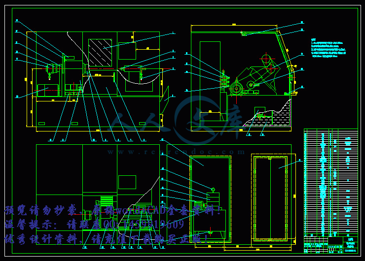
半闭环数控车床总体设计【优秀数控车床设计+3张CAD图纸】

收藏

压缩包内文档预览:
预览图 预览图 预览图 预览图 预览图 预览图 预览图 预览图 预览图 预览图 预览图 预览图 预览图
编号:388047    类型:共享资源    大小:728.41KB    格式:RAR    上传时间:2014-12-23 上传人:QQ14****9609 IP属地:陕西
45
积分
关 键 词:
半闭环 数控车床 半闭环数控车床总体设计 数控车床设计
资源描述:

半闭环数控车床总体设计【优秀数控车床设计+3张CAD图纸】

【带任务书+开题报告+外文翻译+39页@正文24800字】【详情如下】【需要咨询购买全套设计请加QQ1459919609 】.bat

半闭环数控车床总体设计正文.doc

床身.dwg

底座零件图.dwg

开题报告.doc

数控机床编程外文文献翻译.doc

数控车床.dwg

相关资料.doc

计划周记进度检查表.xls

任 务 书

一、题目及专题:

1、题目            半闭环数控车床总体设计            

2、专题                                                

二、课题来源及选题依据

  本次课题来源于: 校企合作开发课题。随着科学技术的发展,机械产品结构越来越合理,其性能、精度和效率日趋提高更新换代频繁,生产类型由大批大量生产向多品种小批量生产转化。因此,对机械产品的加工相应的提出了高精度、高柔度与高度自动化的要求。数字控制机床就是为了解决单件、小批量、特别是复杂型面零件加工的自动化并保证质量要求而产生的。  

摘  要

   本次设计任务来源于校企合作开发课题。

   先调研数控车床的发展状况,随着科学技术的发展,机械产品结构越来越合理,其性能、精度和效率日趋提高更新换代频繁,生产类型由大批大量生产向多品种小批量生产转化。因此,对机械产品的加工相应得提出了高精度、高柔性与高度自动化的要求。数字控制机床就是为了解决单件、小批量、特别是复杂型面零件加工的自动化并保证质量要求而产生的。

   该设计主要考虑两大方面:数控部分和机械部件。首先进行数控车床总体方案的比较,然后确定最佳方案,完成半闭环数控车床的总体布局,绘制出半闭环数控车床的传动系统图,数控车床总体的尺寸联系图。通过对切削力的计算来设计进给系统、刀架、主轴卡盘的夹紧、液压尾座的行程等。完成该数控车床总体设计,总体布局,绘制尺寸联系总图一份,以及床身设计,绘制床身零件图,底座设计,绘制底座零件图。对车床振动的分析来提出加强机床刚度的方法,还有设计该数控机床的排屑装置及尾架装置。最后叙述该机床平时的维护及保养,有利于机床的正常运转。

   预期成果设计出符合机械厂要求的通用型的,半闭环,斜床身,双轴联动,卧式数控车床,尽量满足生产需要,使我们设计的数控机床可靠性,加工精度,变速范围,操作宜人性,工作效率及防护结构,造型等诸多方面更加适合实际的使用要求。

关键词:半闭环;数控车床;总体设计;

Abstract

  This design task comes from the school-enterprise cooperation and development issues.Development of the first investigation of CNC lathe, with the development of science and technology, mechanical product structure more reasonable, and its performance, efficiency and precision of increasingly improved frequent replacement, production types from mass production to the many varieties of small batch production. Therefore, the processing machinery products corresponding to the high precision, high flexibility and high automation. Digital control of machine tool is to solve the one-piece, small batch, especially in the automatic processing of complex surface parts and ensure the quality requirement and produce.

This design mainly consider two aspects: numerical control part and mechanical part. First compared the overall scheme of CNC lathe, and then determine the optimal scheme, to complete the overall layout of CNC lathe, draw the diagram of transmission system semi-closed-loop CNC lathe, CNC lathe overall contact map size. To the design of feed system, turret, spindle chuck through calculation of cutting force, the clamping hydraulic tailstock travel. To complete the overall design of the CNC lathe, general layout, drawing a connection dimension in general, and the body design, drawing machine parts drawing, base design, drawing the base part drawing. Analysis on the lathe vibration proposed method to strengthen the stiffness of machine tools, as well as the design of the CNC machine tool cutting device and a tail frame device. Finally, describes the machine daily maintenance and maintenance, is conducive to the normal operation of the machine.

The expected results of design to meet the requirements of general machinery factory, half closed, slant bed lathe, CNC horizontal lathe, biaxial linkage, as far as possible to meet the need of production, reliability, CNC machine tools enable us to design the machining accuracy, speed range, operation comfort, efficiency and protection structure, other aspects are more suitable for practical use requirements.  

Key words:  Half closed loop;  CNC lathe; The overall design;

目录

摘  要III

AbstractIV

目录V

1 绪论1

1.1 本课题的研究内容和意义1

   1.1.1 本次课题的意义1

1.1.2 本次课题的目的1

1.1.3 本次课题的所要达到的技术要求1

1.2 国内外的发展概况2

1.2.1 国内外数控机床的形势2

1.2.2 数控机床未来发展趋势3

1.3 本课题应达到的要求4

2 数控机床总体方案的比较及其确定5

2.1 调研情况5

2.2 总体方案比较及确定5

2.2.1 机床的总体布局5

2.2.2 机床总体布局的基本要求5

2.2.3 影响总体布局的因素6

2.2.4 简述数控车床的特点6

2.2.5 数控车床总体设计方案16

2.2.6 数控车床总体设计方案28

2.2.7 数控车床总体设计方案的确定10

3 数控车床总体设计11

3.1 数控机床的工作原理11

3.2 数控机床的组成11

3.2.1 程序编制及程序载体11

3.2.2输入装置11

3.2.3数控装置及强电控制装置11

3.2.4伺服驱动系统及位置检测装置12

3.2.5 机床的机械部件12

3.3 参数确定13

3.3.1 主参数和基本参数13

3.3.2 切削用量的选择13

3.3.3 运动参数和动力参数的计算14

3.4 数控车床传动系统图14

3.5 数控车床总体联系图15

3.6 机床的润滑与维护17

4 数控车床部件设计18

4.1 机床底座,床身大件类的设计要求,方法18

4.2 机床的振动和提高刚度措施18

4.2.1  机床振动的类型18

4.2.2 提高机床结构动刚度的措施19

4.3 机床热变形的形成及其特点20

4.4 床身与底座的结构设计21

4.5 机床的隔振22

4.6 排屑装置的设计23

4.7 尾架装置的设计26

5 数控机床的维护与保养27

6 结论29

致谢30

参考文献31

附录32

1 绪论

1.1 本课题的研究内容和意义

 1.1.1 本次课题的意义

随着科学技术发展,机械产品结构越来越合理,其性能、精度和效率日趋提高更新换代频繁,生产类型由大批大量生产向多品种小批量的生产转化。因此,对机械产品的加工相应得提出了高精度、高柔性与高度自动化的要求。

大批大量的产品,如汽车,拖拉机和家用电器的零件,为解决高产优质的问题,多采用专用的自动生产线和自动化车间进行生产。但是应用这些专用生产设备,生产准备周期增长。在机械产品中,单件与小批量产品占到70—80%,这类产品一般都采用通用机床加工,当产品改变时,机床与工艺装备均需作相应的变换和调整,而且通用机床的自动化程度不高,基本上由人工操作,难于提高生产效率和保证产品质量。特别是一些由曲线,曲面轮廓组成的复杂零件,只能借助靠仿形机床,或借助划线和样板用手工操作的方法来加工,加工精度和生产效率受到很大的限制。

数字控制机床就是为了解决单件、小批量、特别是复杂型面零件加工的自动化并保证质量要求而产生的。

柔性制造技术的发展,已经形成了在自动化程度和规模上不同的多钟层次和级别的柔性制造系统。带有自动换刀装置的数控加工中心,是柔性制造的硬件基础,是制造系统的基本级别。在多台加工中心机床或柔性制造单元的基础上,增加刀具和工件在加工设备与包装之间的流通传输和存贮,和必要的工件清洗和尺寸检查设备,并由高一级的计算机整个系统进行控制和管理,这样就构成柔性制造体统。它可以实现多品种的全部机械加工或部件装配,DNC的控制原理是它的控制基础。

随着科学技术和制造工业的飞速发展,迫切需要实现机器的智能化和脑力劳动自动化,以便于适应市场产品需求多变的要求。自动化制造技术不仅需要发展车间制造过程的自动化,而且要全面实现从生产决策,产品设计,市场预测直到销售的整个生产活动的自动化,特别是技术和管理科室的自动化,将这些要求综合成一个完整的生产制造系统,即所谓的计算机集成制造系统。它将一个制造工厂的生态活动进行有机的集成,以实现更高效益,更高柔性的智能化生产。该系统是当今自动化制造技术发展的最高阶段。

参考文献

[1] 王启平. 机床夹具设计.哈尔滨:哈尔滨工业大学出版社,2005.

[2] 朱张校. 工程材料.第3版.北京:清华大学出版社,2003.

[3] 刘鸿文. 材料力学.第4版.北京:高等教育出版社,2003.3.

[4] 王铎. 理论力学(I)第7版.哈尔滨:高等教育出版社,2002.5.

[5] 许兆丰等. 车工工艺学[M].北京:机械工业出版社,1980.

[6] 韩进宏. 互换性与技术测量.北京:机械出版社,2004.7

[7] 成大先等. 机械设计手册[M].北京:化学工业出版社,1995.  

[8] 徐灏主编. 新编机械设计师手册[M].北京:机械工业出版社,1995.

[9] 蔡乐安. 数控车床滚珠丝杠副的研究设计[J].农机化研究,2002.11.

[10] 谢红. 数控机床机器人机械系统设计指导[M].上海:同济大学出版社,2004.8.

[11] 山东济宁博特精密丝杠制造有限公司. 博特产品系列,2002.

[12] SIEMENS公司.西门子(驱动系统和电机).2002.8.

[13] 赵宝生. CNC32数控车床的床身设计[N].机械管理开发,2004.8.

[14] 戴曙主编. 金属切削机床[M].北京:机械工业出版社.1995.10.

[15] Popov E P. Mechanics of materials. 2nd ed.New Jersey:Prentice-Hall Inc,1976.

[16] Gere J M,Timoshenko S P. Mechanics of materials.Second SI Edition.New York:Van Nostrand Reinhold, 1984.

[17] Jeffrey L.Whitten,Lonnie D. Bentley.SYSTEM ANALYSIS AND DESIGN METHODS.Beijing:Higher Education Press.

[18] Orlov P. Fundamentals of Machine Design.Moscow:Mir Pub. 1987.

   [19] Robert J Scjilling. Fundamentals of Robotics-Analysis and Control [M].New Jersey: Prentice Hall,1990.


内容简介:
英文原文CNC machine toolsWhilethespecificintentionandapplicationforCNCmachinesvaryfromonemachinetype toanother,allformsofCNChavecommonbenefits.Herearebutafewofthemoreimportant benefitsofferedbyCNCequipment.ThefirstbenefitofferedbyallformsofCNCmachinetoolsisimprovedautomation. The operatorinterventionrelatedtoproducingworkpiecescanbereducedoreliminated.ManyCNCmachinescanrununattendedduringtheirentiremachiningcycle,freeingtheoperatortodoother tasks.ThisgivestheCNCuserseveralsidebenefitsincludingreducedoperatorfatigue,fewer mistakescausedbyhumanerror,andconsistentandpredictablemachiningtimeforeach workpiece.Sincethemachinewillberunningunderprogramcontrol,theskilllevelrequiredof theCNCoperator(relatedtobasicmachiningpractice)isalsoreducedascomparedtoamachinistproducingworkpieceswithconventionalmachinetools.ThesecondmajorbenefitofCNCtechnologyisconsistentandaccurateworkpieces.TodaysCNCmachinesboastalmostunbelievableaccuracyandrepeatabilityspecifications.Thismeans thatonceaprogramisverified,two,ten,oronethousandidenticalworkpiecescanbeeasily producedwithprecisionandconsistency.AthirdbenefitofferedbymostformsofCNCmachinetoolsisflexibility.Sincethese machinesarerunfromprograms,runningadifferentworkpieceisalmostaseasyasloadinga differentprogram.Onceaprogramhasbeenverifiedandexecutedforoneproductionrun,itcan beeasilyrecalledthenexttimetheworkpieceistoberun.Thisleadstoyetanotherbenefit,fast changeover.Sincethesemachinesareveryeasytosetupandrun,andsinceprogramscanbe easilyloaded,theyallowveryshortsetuptime.Thisisimperativewithtodaysjust-in-time(JIT) product requirements.Motioncontrol-theheartofCNCThemostbasicfunctionofanyCNCmachineisautomatic,precise,andconsistentmotion control.Ratherthanapplyingcompletelymechanicaldevicestocausemotionasisrequiredon mostconventionalmachinetools,CNCmachinesallowmotioncontrolinarevolutionarymanner2.AllformsofCNCequipmenthavetwoormoredirectionsofmotion,calledaxes.Theseaxes canbepreciselyandautomaticallypositionedalongtheirlengthsoftravel.Thetwomostcommonaxistypesarelinear(drivenalongastraightpath)androtary(drivenalongacircularpath).Insteadofcausingmotionbyturningcranksandhandwheelsasisrequiredonconventionalmachinetools,CNCmachinesallowmotionstobecommandedthroughprogrammedcommands.Generallyspeaking,themotiontype(rapid,linear,andcircular),theaxestomove,theamountofmotionandthemotionrate(feedrate)areprogrammablewithalmostallCNCmachinetools.ACNCcommandexecutedwithinthecontroltellsthedrivemotortorotateaprecisenumberoftimes.Therotationofthedrivemotorinturnrotatestheballscrew.Andtheballscrewdrives thelinearaxis(slide).Afeedbackdevice(linearscale)ontheslideallowsthecontroltoconfirm thatthecommandednumberofrotationshastakenplace3. Thougharathercrudeanalogy,thesamebasiclinearmotioncanbefoundonacommontablevise.Asyourotatethevisecrank,yourotatealeadscrewthat,inturn,drivesthemovablejawonthevise.Bycomparison,alinearaxisonaCNCmachinetoolisextremelyprecise.Thenumberofrevolutionsoftheaxisdrivemotorpreciselycontrolstheamountoflinearmotionalongtheaxis.Howaxismotioniscommanded-understandingcoordinatesystems.ItwouldbeinfeasiblefortheCNCusertocauseaxismotionbytryingtotelleachaxisdrivemotorhowmanytimestorotateinordertocommandagivenlinearmotionamount4.(Thiswouldbelikehavingtofigureouthowmanyturnsofthehandleonatablevisewillcausethemovable jawtomoveexactlyoneinch!)Instead,allCNCcontrolsallowaxismotiontobecommandedinamuchsimplerandmorelogicalwaybyutilizingsomeformofcoordinatesystem.Thetwomost popularcoordinatesystemsusedwithCNCmachinesaretherectangularcoordinatesystemand thepolarcoordinatesystem.Byfar,themorepopularofthesetwoistherectangularcoordinate system.TheprogramzeropointestablishesthepointofreferenceformotioncommandsinaCNC program.Thisallowstheprogrammertospecifymovementsfromacommonlocation.Ifprogramzeroischosenwisely,usuallycoordinatesneededfortheprogramcanbetakendirectlyfromtheprint.Withthistechnique,iftheprogrammerwishesthetooltobesenttoapositiononeinchtotherightoftheprogramzeropoint,X1.0iscommanded.Iftheprogrammerwishesthetooltomovetoapositiononeinchabovetheprogramzeropoint,Y1.0iscommanded.Thecontrolwill automaticallydeterminehowmanytimestorotateeachaxisdrivemotorandballscrewtomake theaxisreachthecommandeddestinationpoint.Thisletstheprogrammercommandaxismotioninaverylogicalmanner.Alldiscussionstothispointassumethattheabsolutemodeofprogrammingisused.ThemostcommonCNCwordusedtodesignatetheabsolutemodeisG90.Intheabsolutemode,theendpointsforallmotionswillbespecifiedfromtheprogramzeropoint.Forbeginners,thisisusuallythebestandeasiestmethodofspecifyingendpointsformotioncommands.However,thereisanotherwayofspecifyingendpointsforaxismotion.Intheincrementalmode(commonlyspecifiedbyG91),endpointsformotionsarespecifiedfromthetoolscurrentposition,notfromprogramzero.Withthismethodofcommandingmotion,theprogrammermustalwaysbeaskingHowfarshouldImovethetool?Whiletherearetimeswhentheincrementalmodecanbeveryhelpful,generallyspeaking,thisisthemorecumbersomeanddifficultmethodofspecifyingmotionandbeginnersshouldconcentrateonusingtheabsolutemode.Becarefulwhenmakingmotioncommands.Beginnershavethetendencytothinkincrementally.Ifworkingintheabsolutemode(asbeginnersshould),theprogrammershouldalwaysbeaskingTowhatpositionshouldthetoolbemoved?Thispositionisrelativetoprogramzero,NOTfromthetoolscurrentposition.Asidefrommakingitveryeasytodeterminethecurrentpositionforanycommand,anotherbenefitofworkingintheabsolutemodehastodowithmistakesmadeduringmotioncommands.Intheabsolutemode,ifamotionmistakeismadeinonecommandoftheprogram,onlyonemovementwillbeincorrect.Ontheotherhand,ifamistakeismadeduringincrementalmovements,allmotionsfromthepointofthemistakewillalsobeincorrect.AssigningprogramzeroKeepinmindthattheCNCcontrolmustbetoldthelocationoftheprogramzeropointbyonemeansoranother.HowthisisdonevariesdramaticallyfromoneCNCmachineandcontroltoanother8.One(older)methodistoassignprogramzerointheprogram.Withthismethod,theprogrammertellsthecontrolhowfaritisfromtheprogramzeropointtothestartingpositionofthemachine.ThisiscommonlydonewithaG92(orG50)commandatleastatthebeginningoftheprogramandpossiblyatthebeginningofeachtool.Another,newerandbetterwaytoassignprogramzeroisthroughsomeformofoffset.Refertofig.4.Commonlymachiningcentercontrolmanufacturerscalloffsetsusedtoassignprogramzerofixtureoffsets.Turningcentermanufacturerscommonlycalloffsetsusedtoassignprogramzeroforeachtoolgeometryoffsets.Aflexiblemanufacturingcell(FMC)canbeconsideredasaflexiblemanufacturingsubsystem.ThefollowingdifferencesexistbetweentheFMCandtheFMS:1. AnFMCisnotunderthedirectcontrolofthecentralcomputer.Instead,instructionsfromthecentralcomputerarepassedtothecellcontroller.2. Thecellislimitedinthenumberofpartfamiliesitcanmanufacture.ThefollowingelementsarenormallyfoundinanFMC:CellcontrollerProgrammablelogiccontroller(PLC)MorethanonemachinetoolAmaterialshandlingdevice(robotorpallet)TheFMCexecutesfixedmachiningoperationswithpartsflowingsequentiallybetweenoperations.HighspeedmachiningThetermHighSpeedMachining(HSM)commonlyreferstoendmillingathighrotationalspeedsandhighsurfacefeeds.Forinstance,theroutingofpocketsinaluminumairframesectionswithaveryhighmaterialremovalrate1.Overthepast60years,HSMhasbeenappliedtoawiderangeofmetallicandnon-metallicworkpiecematerials,includingtheproductionofcomponentswithspecificsurfacetopographyrequirementsandmachiningofmaterialswithhardnessof50HRCandabove.Withmoststeelcomponentshardenedtoapproximately32-42HRC,machiningoptionscurrentlyinclude:Roughmachiningandsemi-finishingofthematerialinitssoft(annealed)conditionheattreatmenttoachievethefinalrequiredhardness=63HRCmachiningofelectrodesandElectricalDischargeMachining(EDM)ofspecificpartsofdiesandmoulds(specificallysmallradiianddeepcavitieswithlimitedaccessibilityformetalcuttingtools)finishingandsuper-finishingofcylindrical/flat/cavitysurfaceswithappropriatecementedcarbide,cermet,solidcarbide,mixedceramicorpolycrystallinecubicboronnitride(PCBN)Formanycomponents,theproductionprocessinvolvesacombinationoftheseoptionsandinthecaseofdiesandmouldsitalsoincludestimeconsuminghandfinishing.Consequently,productioncostscanbehighandleadtimesexcessive.Itistypicalinthedieandmouldindustrytoproduceoneorjustafewtoolsofthesamedesign.Theprocessinvolvesconstantchangestothedesign,andbecauseofthesechangesthereisalsoacorrespondingneedformeasuringandreverseengineering.Themaincriteriaisthequalitylevelofthedieormouldregardingdimensional,geometricandsurfaceaccuracy.Ifthequalitylevelaftermachiningispoorandifitcannotmeettherequirements,therewillbeavaryingneedofmanualfinishingwork.Thisworkproducessatisfactorysurfaceaccuracy,butitalwayshasanegativeimpactonthedimensionalandgeometricaccuracy.Oneofthemainaimsforthedieandmouldindustryhasbeen,andstillis,toreduceoreliminatetheneedformanualpolishingandthusimprovethequalityandshortentheproductioncostsandleadtimes.MaineconomicalandtechnicalfactorsforthedevelopmentofHSMSurvivalTheeverincreasingcompetitioninthemarketplaceiscontinuallysettingnewstandards.Thedemandsontimeandcostefficiencyisgettinghigherandhigher.Thishasforcedthedevelopmentofnewprocessesandproductiontechniquestotakeplace.HSM provideshopeandsolutions.MaterialsThedevelopmentofnew,moredifficulttomachinematerialshasunderlinedthenecessitytofindnewmachiningsolutions.Theaerospaceindustryhasitsheatresistantandstainlesssteelalloys.Theautomotiveindustryhasdifferentbimetalcompositions,CompactGraphiteIronandaneverincreasingvolumeofaluminum3.Thedieandmouldindustrymainlyhastofacetheproblemofmachininghighhardenedtoolsteels,fromroughingtofinishing.QualityThedemandforhighercomponentorproductqualityistheresultofeverincreasingcompetition.HSM,ifappliedcorrectly,offersanumberofsolutionsinthisarea.Substitutionofmanualfinishingisoneexample,whichisespeciallyimportantondiesandmouldsorcomponentswithacomplex3Dgeometry.ProcessesThedemandsonshorterthroughputtimesviafewersetupsandsimplifiedflows(logistics)caninmostcases,besolvedbyHSM.Atypicaltargetwithinthedieandmouldindustryistocompletelymachinefullyhardenedsmallsizedtoolsinonesetup.CostlyandtimeconsumingEDMprocessescanalsobereducedoreliminatedwithHSM.Design&developmentOneofthemaintoolsintodayscompetitionistosellproductsonthevalueofnovelty.Theaverageproductlifecycleoncarstodayis4years,computersandaccessories1.5years,handphones3months.OneoftheprerequisitesofthisdevelopmentoffastdesignchangesandrapidproductdevelopmenttimeistheHSMtechnique.ComplexproductsThereisanincreaseofmulti-functionalsurfacesoncomponents,suchasnewdesignofturbinebladesgivingnewandoptimizedfunctionsandfeatures.Earlierdesignsallowedpolishingbyhandorwithrobots(manipulators).Turbinebladeswithnew,moresophisticateddesignshavetobefinishedviamachiningandpreferablybyHSM.Therearealsomoreandmoreexamplesofthinwalledworkpiecesthathavetobemachined(medicalequipment,electronics,productsfordefence,computerparts)ProductionequipmentThestrongdevelopmentofcuttingmaterials,holdingtools,machinetools,control sandespeciallyCAD/CAMfeaturesandequipment,hasopenedpossibilitiesthatmustbemetwithnewproductionmethodsandtechniques5.DefinitionofHSMSalomonstheory,Machiningwithhighcuttingspeeds.onwhich,in1931,tookoutaGermanpatent,assumesthatatacertaincuttingspeed(5-10timeshigherthaninconventionalmachining),thechipremovaltemperatureatthecuttingedgewillstarttodecrease.Giventheconclusion:.seemstogiveachancetoimproveproductivityinmachiningwithconventionaltoolsathighcuttingspeeds.Modernresearch,unfortunately,hasnotbeenabletoverifythistheorytotally.Thereisarelativedecreaseofthetemperatureatthecuttingedgethatstartsatcertaincuttingspeedsfordifferentmaterials.Thedecreaseissmallforsteelandcastiron.Butlargerforaluminumandothernon-ferrousmetals.ThedefinitionofHSMmustbebasedonotherfactors.Giventodaystechnology,highspeedisgenerallyacceptedtomeansurfacespeedsbetween1and10kilometersperminuteorroughly3300to33000feetperminute.Speedsabove10km/minareintheultra-highspeedcategory,andarelargelytherealmofexperimentalmetalcutting.Obviously,thespindlerotationsrequiredtoachievethesesurfacecuttingspeedsaredirectlyrelatedtothediameterofthetoolsbeingused.Onetrendwhichisveryevidenttodayistheuseofverylargecutterdiametersfortheseapplications-andthishasimportantimplicationsfortooldesign.Therearemanyopinions,manymythsandmanydifferentwaystodefineHSM.MaintenanceandtroubleshootingMaintenanceforahorizontalMCThefollowingisalistofrequiredregularmaintenanceforaHorizontalMachiningCenterasshowninfig.5.Listedarethefrequencyofservice,capacities,andtypeoffluidsrequired.Theserequiredspecificationsmustbefollowedinordertokeepyourmachineingoodworkingorderandprotectyourwarranty.DailyTopoffcoolantleveleveryeighthourshift(especiallyduringheavyTSCusage).Checkwaylubelubricationtanklevel.Cleanchipsfromwaycoversandbottompan.Cleanchipsfromtoolchanger.Wipespindletaperwithacleanclothragandapplylightoil.WeeklyCheckforproperoperationofautodrainonfilterregulator.OnmachineswiththeTSCoption,cleanthechipbasketonthecoolanttank.Removethetankcoverandremoveanysedimentinsidethetank.BecarefultodisconnectthecoolantpumpfromthecontrollerandPOWEROFFthecontrolbeforeworkingonthecoolanttank.DothismonthlyformachineswithouttheTSCoption.Checkairgauge/regulatorfor85psi.FormachineswiththeTSCoption,placeadabofgreaseontheV-flangeoftools.DothismonthlyformachineswithouttheTSCoption.Cleanexteriorsurfaceswithmildcleaner.DONOTusesolvents.Checkthehydrauliccounterbalancepressureaccordingtothemachinesspecifications.Placeadabofgreaseontheoutsideedgeofthefingersofthetoolchangerandrunthroughalltools.MonthlyCheckoillevelingearbox.Addoiluntiloilbeginsdrippingfromoverflowtubeatbottomofsumptank.Cleanpadsonbottomofpallets.CleanthelocatingpadsontheA-axisandtheloadstation.Thisrequiresremovingthepallet.Inspectwaycoversforproperoperationandlubricatewithlightoil,ifnecessary.SixmonthsReplacecoolantandthoroughlycleanthecoolanttank.Checkallhosesandlubricationlinesforcracking.AnnuallyReplacethegearboxoil.Draintheoilfromthegearbox,andslowlyrefillitwith2quartsofMobilDTE25oil.Checkoilfilterandcleanoutresidueatbottomforthelubricationchart.Replaceairfilteroncontrolboxevery2years.Mineralcuttingoilswilldamagerubberbasedcomponentsthroughoutthemachine.TroubleshootingThissectionisintendedforuseindeterminingthesolutiontoaknownproblem.SolutionsgivenareintendedtogivetheindividualservicingtheCNCapatterntofollowin,first,determiningtheproblemssourceand,second,solvingtheproblem.UsecommonsenseManyproblemsareeasilyovercomebycorrectlyevaluatingthesituation.Allmachineoperationsarecomposedofaprogram,tools,andtooling.Youmustlookatallthreebeforeblamingoneasthefaultarea.Ifaboredholeischatteringbecauseofanoverextendedboringbar,dontexpectthemachinetocorrectthefault.Dontsuspectmachineaccuracyifthevisebendsthepart.Dontclaimholemis-positioningifyoudontfirstcenter-drillthehole.FindtheproblemfirstManymechanicstearintothingsbeforetheyunderstandtheproblem,hopingthatitwillappearastheygo.Weknowthisfromthefactthatmorethanhalfofallwarrantyreturnedpartsareingoodworkingorder.Ifthespindledoesntturn,rememberthatthespindleisconnectedtothegearbox,whichisconnectedtothespindlemotor,whichisdrivenbythespindledrive,whichisconnectedtotheI/OBOARD,whichisdrivenbytheMOCON,whichisdrivenbytheprocessor.Themoralhereisdontreplacethespindledriveifthebeltisbroken.Findtheproblemfirst;dontjustreplacetheeasiestparttogetto.DontinkerwiththemachineTherearehundredsofparameters,wires,switches,etc.,thatyoucanchangeinthismachine.Dontstartrandomlychangingpartsandparameters.Remember,thereisagoodchancethatifyouchangesomething,youwillincorrectlyinstallitorbreaksomethingelseintheprocess6.Considerforamomentchangingtheprocessorsboard.First,youhavetodownloadallparameters,removeadozenconnectors,replacetheboard,reconnectandreload,andifyoumakeonemistakeorbendonetinypinitWONTWORK.Youalwaysneedtoconsidertheriskofaccidentallydamagingthemachineanytimeyouworkonit.Itischeapinsurancetodouble-checkasuspectpartbeforephysicallychangingit.Thelessworkyoudoonthemachinethebetter. 中文译文数控机床 虽然各种数控机床的功能和应用各不相同,但它们有着共同的优点。这里是数控设备提供的比较重要的几个优点。 各种数控机床的第一个优点是自动化程度提高了。零件制造过程中的人为干预减少或者免除了。整个加工循环中,很多数控机床处于无人照看状态,这使操作员被解放出来,可以干别的工作。数控机床用户得到的几个额外好处是:数控机床减小了操作员的疲劳程度,减少了人为误差,工件加工时间一致而且可预测。由于机床在程序的控制下运行,与操作普通机床的机械师要求的技能水平相比,对数控操作员的技能水平要求(与基本加工实践相关)也降低了。 数控技术的第二个优点是工件的一致性好,加工精度高。现在的数控机床宣称的精度以及重复定位精度几乎令人难以置信。这意味着,一旦程序被验证是正确的,可以很容易地加工出2个、10个或1000个相同的零件,而且它们的精度高,一致性好。大多数数控机床的第三个优点是柔性强。由于这些机床在程序的控制下工作,加工不同的工件易如在数控系统中装载一个不同的程序而己。一旦程序验证正确,并且运行一次,下次加工工件的时候,可以很方便地重新调用程序。这又带来另一个好处可以快速切换不同工件的加工。由于这些机床很容易调整并运行,也由于很容易装载加工程序,因此机床的调试时间很短。这是当今准时生产制造模式所要求的。 任何数控机床最基本的功能是具有自动、精确、一致的运动控制。大多数普通机床完全运用机械装置实现其所需的运动,而数控机床是以一种全新的方式控制机床的运动。各种数控设备有两个或多个运动方向,称为轴。这些轴沿着其长度方向精确、自动定位。最常用的两类轴是直线轴(沿直线轨迹)和旋转轴(沿圆形轨迹)。普通机床需通过旋转摇柄和手轮产生运动,而数控机床通过编程指令产生运动。通常,几乎所有的数控机床的运动类型(快速定位、直线插补和圆弧插补)、移动轴、移动距离以及移动速度(进给速度)都是可编程的。 数控系统中的CNC指令命令驱动电机旋转某一精确的转数,驱动电机的旋转随即使滚珠丝杠旋转,滚珠丝杠将旋转运动转换成直线轴(滑台)运动。滑台上的反馈装置(直线光栅尺)使数控系统确认指令转数已完成。 普通的台虎钳上有着同样的基本直线运动,尽管这是相当原始的类比。旋转虎钳摇柄就是旋转丝杠,丝杠带动虎钳钳口移动。与台虎钳相比,数控机床的直线轴是非常精确的,轴的驱动电机的转数精确控制直线轴的移动距离。轴运动命令的方式-理解坐标 对CNC用户来说,为了达到给定的直线移动量而指令各轴驱动电机旋转多少转,从而使坐标轴运动,这种方法是不可行的。(这就好像为了使钳口准确移动1英寸需要计算出台虎钳摇柄的转数!)事实上,所有的数控系统都能通过采用坐标系的形式以一种较为简单而且合理的方式来指令轴的运动。数控机床上使用最广泛的两种坐标系是直角坐标系和极坐标系。目前用得较多的是直角坐标系。编程零点建立数控程序中运动命令的参考点。这使得操作员能从一个公共点开始指定轴运动。如果编程零点选择恰当,程序所需坐标通常可从图纸上直接获得。如果编程员希望刀具移动到编程零点右方1英寸(25.4毫米)的位置,则用这种方法指令X1.0即可。如果编程员希望刀具移动到编程零点上方1英寸的位置,则指令Y1.0。数控系统会自动确定(计算)各轴驱动电机和滚珠丝杠要转动多少转,使坐标轴到达指令的目标位置。这使编程员以非常合理的方式命令轴的运动。理解绝对和相对运动至此,所有的讨论都假设采用的是绝对编程方式。用于指定绝对方式的最常用的数控代码是G90。绝对方式下,所有运动终点的指定都是以编程零点为起点。对初学者来说,这通常是最好也是最容易的指定轴运动终点的方法,但还有另外一种指定轴运动终点的方法。增量方式(通常用G91指定)下,运动终点的指定是以刀具的当前位置为起点,而不是编程零点。用这种方法指定轴运动,编程员往往会问“我该将刀具移动多远的距离?”,尽管增量方式多数时候很有用,但一般说来,这种方法指定轴运动较麻烦、困难,初学者应该重点使用绝对方式。指令轴运动时一定要小心。初学者往往以增量方式思考问题。如果工作在绝对方式(初学者应该如此),编程员应始终在问“刀具应该移动到什么位置?”,这个位置是相对于编程零点这个固定位置而言,而不是相对于刀具当前位置。绝对工作方式很容易确定指令当前位置,除此之外,它的另外一个好处涉及轴运动中的错误。绝对方式下,如果程序的一个轴运动指令出错,则只有一个运动是不正确的。而另一方面,如果在增量运动过程中出错,则从出错的那一点起,所有的运动都是不正确的指定编程零点记住必须以某种方式对数控系统指定编程零点的位置。指定编程零点的方式随数控机床和数控系统的不同而很不相同。(较老的)一种方法是在程序中指定编程零点。用这种方法,编程员告诉数控系统从编程零点到机床起始点的距离。通常用G92(或G50)在程序的一开始指定,很可能在各把刀具的开头指定编程零点。另一种较新、更好的指定编程零点的方法是通过偏置的形式,见图4。通常,加工中心上用于指定编程零点的偏置被称作夹具偏置,车削中心上用于指定编程零点的偏置被称作刀具几何偏置。柔性制造单元柔性制造单元(FMC)被认为是柔性制造子系统。以下是FMC和FMS之间的区别:1.FMC不受中央计算机的直接控制,中央计算机发出的指令被传送到单元控制器。2.FMC能制造的零件族的数目有限。FMC一般由下列部分组成:单元控制器可编程逻辑控制器(PLC)一台以上的机床物流设备(机器人或托盘)FMC按顺序对零件流执行固定的加工操作。高速加工术语“高速加工(HSM)”一般是指在高转速和大进给量下的立铣。例如,以很高的金属切除率对铝合金飞机翼架的凹处进行切削。在过去的60年中,高速加工己经广泛应用于金属与非金属材料,包括有特定表面形状要求的零件生产和硬度高于或等于HRC50的材料切削。对于大部分淬火到约为HRC32-42的钢零件,当前的切削选项包括:在软(退火)工况下材料的粗加工和半精加工达到最终硬度要求为HRC63的热处理模具行业的某些零件的电极加工和放电加工(EDM)(特别是金属切削刀具难以加工的小半径圆弧和深凹穴)用适合的硬质合金、金属陶瓷、整体硬质合金、混合陶瓷或多晶立方氮化硼(PCBN)刀具进行的圆柱平面凹穴表面的精加工和超精加工。对于许多零件,生产过程牵涉到这些选项的组合,在模具制造案例中,它还包括费时的精加工,结果导致生产成本高和准备时间长。在模具制造业中典型的是仅生产一个或几个同一产品。生产过程中产品的设计不断改变,由于产品改变,模具制造中需要测量与反求工程。加工的主要标准是模具的尺寸和表面粗糙度方面的质量水平。如果加工后的质量水平低,不能满足要求,就需手工精加工。手工精加工可产生令人满意的表面粗糙度,但是对尺寸和几何精度总是产生不好的影响。模具制造业的主要目标之一,一直是并且仍然是减少或免除手工抛光,从而提高质量、降低生产成本和缩短准备时间。高速加工发展的主要经济和技术因素生存日益激烈的市场竞争导致不断设立新的标准,对时间和成本效率的要求越来越高,这就迫使新工艺和生产技术不断发展。高速加工提供了希望和解决方案材料新型难加工材料的开发迫切需要寻找新的切削解决方案。航空航天业使用耐热合金钢和不锈钢,汽车工业使用了不同的双金属材料、小石墨铸铁,并增加了铝的用量。模具制造业必须面对切削高硬度的淬火钢
温馨提示:
1: 本站所有资源如无特殊说明,都需要本地电脑安装OFFICE2007和PDF阅读器。图纸软件为CAD,CAXA,PROE,UG,SolidWorks等.压缩文件请下载最新的WinRAR软件解压。
2: 本站的文档不包含任何第三方提供的附件图纸等,如果需要附件,请联系上传者。文件的所有权益归上传用户所有。
3.本站RAR压缩包中若带图纸,网页内容里面会有图纸预览,若没有图纸预览就没有图纸。
4. 未经权益所有人同意不得将文件中的内容挪作商业或盈利用途。
5. 人人文库网仅提供信息存储空间,仅对用户上传内容的表现方式做保护处理,对用户上传分享的文档内容本身不做任何修改或编辑,并不能对任何下载内容负责。
6. 下载文件中如有侵权或不适当内容,请与我们联系,我们立即纠正。
7. 本站不保证下载资源的准确性、安全性和完整性, 同时也不承担用户因使用这些下载资源对自己和他人造成任何形式的伤害或损失。
提示  人人文库网所有资源均是用户自行上传分享,仅供网友学习交流,未经上传用户书面授权,请勿作他用。
关于本文
本文标题:半闭环数控车床总体设计【优秀数控车床设计+3张CAD图纸】
链接地址:https://www.renrendoc.com/p-388047.html

官方联系方式

2:不支持迅雷下载,请使用浏览器下载   
3:不支持QQ浏览器下载,请用其他浏览器   
4:下载后的文档和图纸-无水印   
5:文档经过压缩,下载后原文更清晰   
关于我们 - 网站声明 - 网站地图 - 资源地图 - 友情链接 - 网站客服 - 联系我们

网站客服QQ:2881952447     

copyright@ 2020-2025  renrendoc.com 人人文库版权所有   联系电话:400-852-1180

备案号:蜀ICP备2022000484号-2       经营许可证: 川B2-20220663       公网安备川公网安备: 51019002004831号

本站为文档C2C交易模式,即用户上传的文档直接被用户下载,本站只是中间服务平台,本站所有文档下载所得的收益归上传人(含作者)所有。人人文库网仅提供信息存储空间,仅对用户上传内容的表现方式做保护处理,对上载内容本身不做任何修改或编辑。若文档所含内容侵犯了您的版权或隐私,请立即通知人人文库网,我们立即给予删除!