说明书.doc

数控铣床电主轴系统的设计【优秀含3张CAD图纸】

收藏

压缩包内文档预览:(预览前20页/共77页)
预览图 预览图 预览图 预览图 预览图 预览图 预览图 预览图 预览图 预览图 预览图 预览图 预览图 预览图 预览图 预览图 预览图 预览图 预览图 预览图
编号:396391    类型:共享资源    大小:2.44MB    格式:RAR    上传时间:2015-01-16 上传人:QQ14****9609 IP属地:陕西
45
积分
关 键 词:
数控铣床 电机主轴 控制系统 机械设计 数控铣床电主轴系统的设计
资源描述:

数控铣床电主轴系统的设计【优秀含3张CAD图纸】

【带开题报告+外文文翻译+73页@正文38500字】【详情如下】【需要咨询购买全套设计请加QQ1459919609 】.bat

CPE_2007_SRM_Final_ZAFT_WUT.pdf

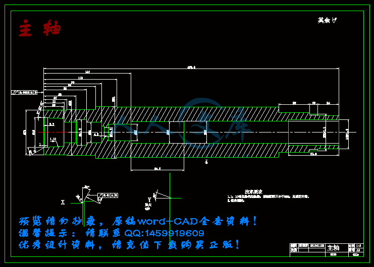
主轴.dwg

主轴装配图.dwg

外文翻译2.doc

开题报告.doc

拉刀装配图.dwg

摘要.doc

简介.txt

说明书.doc

开 题 报 告

题   目    数控铣床电主轴系统的设计                        

题  目数控铣床电主轴系统的设计

一、选题的目的及研究意义

选题的目的:

毕业设计是我们测控技术与仪器专业学生的一次重要实践环节,它将把我们四年里所学的知识贯通于一体,一个好的设计不仅能表现出自己对知识的掌握程度,同时它对我们今后的工作也起到了铺垫作用,因此我们在选题时应当考虑到最近国家在技术领域的发展趋势以及自己以后将从事的工作形式。

随着社会生产和科学技术的迅速发展,机械产品日趋精密复杂,且要求频繁改型,特别是在宇航,造船,军事等领域所需的机械零件,精度要求高,形状复杂,批量小。加工这类产品需要经常改装和调整设备,普通机床已不能适应这些要求。数控机床应用而生。这种新型机床具有适应性强,加工精度高,加工质量稳定和生产效率高等优点。他综合应用了电子计算机,自动控制,伺服驱动,精密测量和新型机械结构等多方面的技术成果,是今后数控机床的发展方向。而电主轴是高速切削机床最重要的部件也是实现高速和超高速加工的关键技术之一 ,它要求动平衡高,刚性好,回转精度高,有良好的热稳定性,能传递足够的力矩和功率,能承受高的离心力,带有准确的测温装置和高效的冷却装置。它的好坏对机床性能影响很大,因此选这个题具有现实意义,又具有市场需求。

研究意义:

现代化高速主轴系统采用的是电主轴,即所谓的机电一体化主轴.电主轴及驱动系统是一套完整的,独立的功能部件,它是高速电机和精密主轴的有机结合体.它不仅能使主轴直接产生电磁转矩,具有低损耗,长寿命的特点,而且还具有高精度,高转速,低振动,低噪音等优良的机械特性.根据最新市场调查显示,我国电主轴单元需求量很大,并呈递增的势头,市场前景广阔,其中进口产品所占份额.数控机床铣削用电主轴, 正是在市场的呼唤下,结合自身优势研制开发的一种新型产品.传统的磨用电主轴单元直接安装于机床鞍型座孔中,且多为卧式安装.靠砂轮接头通过螺纹联接将砂轮安装在电主轴上,采用恒转矩调速输出功率。因此可以说电主轴的发展水平是衡量一个国家机械制造业的实力。所以我们对它的研究具有很多的实际意义,并且有许多技术有待解决。

本次课程设计通过对高速电主轴结构和动静态特性的有限元分为优化主轴结构和改善电主轴的动静态及热态特性提供必要的理论依据,为高速电主轴的研究开发和应用奠定基础

二、综述与本课题相关领域的研究现状、发展趋势、研究方法及应用领域等

研究现状:

近年来 ,国际上大功率高速铣削和钻削电主轴技术发展很快。德国GMN公司Darmstadf工业大学协助下 ,开发HC系列高速电主轴 ,日本NSK公司的M系列 ,意大利G&F公司的EFA、EMC系列 ,瑞士STEP -TEC公司的HVC系列电主轴都具有功率大、刚度高及调速范围宽的特性 ,完全适用于高速、高效切削。瑞士Mikron公司开发的高性能加工中心 ,装备有STEP -TEC公司制造的转速为20000r /min的电主轴 ,并可选配42000r/ min的电主轴国产电主轴技术现状电主轴在我国起步也很早 ,2 0世纪 5 0年代末、60年代初就已经将电主轴应用于工业生产中 ,但多用于专用内圆磨床 ,如轴承行业、油泵和油嘴行业中的专用内孔磨床等。直到 90年代中后期 ,由于国内市场需要 ,洛阳轴承研究所开始开发其他用途的电主轴 ,如印制电路板 (PCB)行业钻小孔用高速电主轴、小型数控铣床用电主轴等。多年来 ,依次完成DZ、GDZ、2GDZ系列数控磨床用电主轴、XD系列数控铣床用电主轴、CD系列 数控车床用电主轴、ZD系列PCB行业钻、铣削用电主轴、LD系列高档管材旋辗用电主轴和ED系列高速离心机用电主轴等的研究与开发。生产的PCB行业用钻、铣削电主轴,转速达到105000r/ min ,为国内PCB行业数控机床所普遍采用 ,并且已经替代部分进口产品。

发展趋势:

随着机床技术、高速切削技术的发展和实际应用的需要,人们对机床电主轴的性能也提出了越来越高的要求,电主轴技术的发展趋势主要表现在以下几个方面:

( 1 )向电机内装式电主轴单元方向发展加工中心和数控机床采用皮带传动 ,转速一般能达到6000r/min ;采用直连式传动 ,转速一般能达到8000r/min。转速再高会产生较大的振动噪声 ,且皮带、齿轮传动将造成机床结构复杂 ,因此 8000r/min以上的加工中心和数控机床多采用内装式电主轴单元。内装式电主轴单元是将电机转子直接套装在精密主轴上 ,通过交流无级变频调速使主轴获得所需工作速度和扭矩。它具有调速比大 ,调速方法简单 ,传动平稳 ,结构简单 ,振动噪声小和使用维修方便等优点。虚拟 (并联 )机床、五面体加工中心等高档机床由于结构的原因必须采用内装式电主轴型式。继德国西门子公司和日本NSK公司先后开发了适用于数控机床的内装式电主轴单元后 ,德国的GMN公司、意大利的GAMFIOR公司也转向开发数控机床用内装式电主轴单元 ,电机内装式主轴单元成为当今国内外数控金属切削加工设备主轴系统技术发展的主要趋势之一。

( 2 )向高速、大功率方向发展随着刀具技术、高速进给技术的进步和发展 ,要求机床电主轴的转速越来越高 ,如意大利GAMFIOR公司的数控铣床用电主轴的最高转速可达到 75000r/min(磁悬浮轴承 ) ,功率 4kW ;德国GMN公司的数控铣床用电主轴的最高转速也达到了 60000r/min ,功率 5kW ;瑞士STEP -TEC公司的数控铣床用电主轴的最高转速为 42000r/min,功率 1 3kW。

(3)向低速、大扭矩方向发展在要求电主轴能够实现较高转速的同时 ,低速段要求尽可能大的输出扭矩 ,以满足能在同一台机床上进行低速重切削和高速精加工的要求。如德国GMN公司、意大利GAMFIOR公司和瑞士STEP -TEC公司等制造商生产的加工中心用电主轴 ,其低速段的输出扭矩可以达到 200N·m以上 ,最高工作转速达到 75000r/min。

( 4 )向高精度、高刚度方向发展精密数控机床需要主轴有高的回转精度、高的刚度 ,因此 ,要求电主轴采用精度高、内径尽可能大、高速性能好的轴承和先进的润滑技术 ,如陶瓷球混合轴承、电磁轴承以及油气润滑方法等。

( 5 )向精确定向 (准停 )方向发展加工中心等数控机床由于自动换刀、刚性攻丝及精确传动的需要 ,要求电主轴能够实现切向准停功能。如德国INDRMAT的主轴电机能够实现的准停精度为 ( 1400000 )r,即 0.001°。

( 6)向快速起、停方向发展为了缩短辅助时间 ,提高效率 ,要求数控机床电主轴的起、停时间越短越好 ,因此需要很高的起、停加速度。目前 ,国外电主轴的加、减速度已达到 1g以上 ,全速起、停时间在 1s以下。

( 7)向超高速方向发展对于某些特殊零件的加工和特殊行业 ,要求切削工具的转速越高越好 ,如微型轴承的小孔磨削加工、油泵油嘴的小孔和超小孔的磨削加工、印制电路板 (PCB)行业的小孔 (0.2~ 6mm)及超小孔 (0.2mm以下 )的钻削加工等 ,所用电主轴的转速已经达到 150000r/min以上。

2 。我国数控机床用电主轴技术与国际水平的差距 ,主要表现在以下几个方面 :(1 )在电主轴的低速大扭矩方面 ,国外产品低速段的输出扭矩最大可以达到 300N·m以上 ,而我国目前多在100N·m以内。( 2 )在高速方面 ,国外加工中心等数控机床用电主轴的转速已经达到了 75000r/min(意大利的GAMFIOR公司 ) ,而我国则多在15000r/min以下 ;其他类型的电主轴 ,国外最高转速可达到300000r/min(日本SEIKOSEIKI公司 ) ,而国内电主轴的最高转速为150000r/min (洛阳轴承研究所 )。( 3)在电主轴的轴承润滑方面 ,国外高速和超高速电主轴已经普遍采用可靠性好、对环境污染小的油气 (oil +air)润滑技术 ,而我国现在仍然多采用油脂润滑或油雾润滑 ,制约着电主轴转速的进一步提高。( 4 )在电主轴的支承方面 ,国外采用的轴承有钢制轴承、陶瓷球混合轴承、全陶瓷轴承和流体动、静压轴承、磁悬浮轴承等 ,国内则多采用钢制轴承 ,近年来也采用陶瓷球混合轴承 ,但数量不多 ,不能满足电主轴转速日益提高的要求。( 5 )在其他与电主轴相关的配套技术方面 ,如主轴电机矢量控制和交流伺服控制技术、精确定向 (准停 )技术、快速起动与停止技术以及HSK刀柄制造与应用技术等 ,国内仍然不够成熟 ,或不能满足实际需要

研究方法

根据电主轴的实际运行特点,将轴承、主轴、电动机、轴承座作为一个系统进行动力学分析,同时充分考虑支承刚度非线性、主轴热扩散及热变形等热态性能对主轴动态性能的影响,并对整个电主轴进行动态优化设计。

应用领域:

采用高速电主轴静态设计方法,选择相关参数进行设计。高速电主轴由于实现了电机和机床主轴的一体化功能,可广泛应用于各种机床和各种工业机械如:磨床,磨头;车床;数控加工中心;数控铣床;钻铣床;雕刻机;PCB钻孔;高速离心喷雾;木工镂铣等。际上高性能、高速、高精度数控机床普遍采用电主轴单元。在多工件复合加工机床、多轴联动多面体加工机床、并联机床和柔性加工单元中,电主轴更具有机械主轴不可替代的优越性。

三、对本课题将要解决的主要问题及解决问题的思路与方法、拟采用的研究方法(技术路线)或设计(实验)方案进行说明

主要问题:对电主轴进行结构设计时,需要考虑以下几个问题:首先,它是一种精密部件,主轴轴承需要调整或更换,要求轴上零件便于装拆。其次,主轴轴承是在预紧力作用下工作的,轴承的定位元件在高速下需承受一定的轴向力;电机的转子安装在主轴上,它与主轴的结合面要传递电机的转矩。第三,主轴在高速下运转时,动平衡要求非常高,电机转子与机床主轴之间不宜采用键联结来传递扭矩。第四,拉刀机构的确定,主轴准停装置的确定和解决零件配合中的连接问题冷却管道的设计,以及轴上零件的连接问题等等。

为了解决上述问题,将采用如下方法:

1. 主电机置于前后轴承之间。这是电主轴的一种基本的结构形式。它采用支承结构,支承受力方式为外撑式。

2. 前后轴承均采用串联安装方式,后支撑援用小尺寸轴承,降低了速度因素值,对主轴整体刚度影响不大,对保持整个轴承的使用寿命十分有利。优点是主轴单元的轴向尺寸较短,主轴刚度大,功率大,比较适合大,中型高速机床。目前大多数电主轴都采用这种结构形式。

3. HSK刀柄加紧系统采用膨胀式加紧机构,在装夹刀柄的过程中,拉杆拉动膨胀式弹簧夹头,夹头与刀柄的内孔斜面发生接触并带动刀柄,进而达到刀柄与主轴内孔的配合。当处于高速旋转状态时,外涨式弹簧夹爪所受离心力会增加刀柄的拉紧作用,是静态时所受加紧力的近两倍,使主轴和刀柄的联结更可靠,承载能力更强。由于夹紧力的作用,HSK刀柄法兰面与主轴端面紧密贴合,法兰面起到了支撑作用,它阻止了HSK刀柄的变形,提高了HSK工具系统的刚度。只要刀柄法兰面与主轴端面不分离,即整个表面存在一定的接触压应力,那么这种支撑作用就一直存在。当HSK刀柄受到载荷(径向力或弯矩)时,随着载荷的增加,HSK法兰面某一侧的接触应力将逐渐减少。刀柄的变形主要是其前端圆柱部分的变形,由于该部分圆柱直径比同规格的BT刀柄大许多,而刚度与直径的四次方成正比,所以 HSK工具系统的刚度比传统的BT工具系统的刚度高5~7倍。

4. 主轴轴承的各种摩擦会随主轴转速的升高而加剧,发热量也随着增大,温升增加,轴承的预紧力增加。反过来又加剧了轴承的发热,因此轴承将采用油气润滑。

5. 采用外循环水冷却系统,在主轴外设有冷却水箱和冷却水循环泵,在内置电机定子的外加

——铝质的外套,外套的外壁开有槽。电主轴工作时,循环水泵连续地将冷却水压入电主轴内,在槽流动,并形成循环,将电机产生的热量带到电主轴外,达到冷却电机的目的。

四、检索与本课题有关参考文献资料的简要说明

[1]. 张伯霖,杨庆东,陈长年. 高速切削技术及应用. 北京:机械工业出版社,2002,9

[2]. 严武升. 超高速电主轴的几个问题. 机械科学与开发,1998,Vol.17:428~430

[3]. 张伯霖,张志润,肖曙红. 超高速加工与机床的零传动.中国机械工程,1996,7(5):37~41

[4]. 张伯霖. 超高速切削的关键技术. 机床,1993. 11

[5]. 匿名. 数控机床为什么用境外部件配套. 中国机床商业网,2003.09.05.

[6]. 马家驹等. 高速角接触球轴承的结构. 机电工程. 1998(5).

[7]. 克利宗 AC 等.转子动力学-弹性支承. 北京: 科学出版社,1987

[8]. 哈托 DJ. 振动分析的矩阵计算机方法. 北京: 机械工业出版社,1982

[9]. 胡海昌. 弹性力学的变分原理及其应用. 北京: 科学出版社,1981

[10]. Spur G .等. 主轴-轴承系统的计算: 利用结构修正法确定静态和动态性能. 国外轴承,1991,(4)

[11]. Brandlein J. 滚动轴承支承机床主轴的特性. 国外轴承,1991,(2)

[12]. 刘鸿文. 材料力学. 北京: 高等教育出版社,1979

[13]. 机械设计手册. 机械工业出版社,1995

[14]. 吴善元 . 金属切削原理与刀具 . 机械工业出版社,1995

[15]. 机床设计手册 . 机械工业出版社 ,1995

[16]. 机械加工工艺师手册 . 机械工业出版社,2001.8

[16]. 编写组,机床设计手册《第三册》 .机械工业出版社 ,1986.12

[18]. 戴曙,金属切削机床设计,机械工业出版社,1981.

[19].胡育辉.数控铣床加工中心.辽宁科学技术出版社,2005.1.

[20].徐宏海,谢富春等。数控铣床.化学工业出版社,2006,12.

[21].洛阳轴承研究所 .磨削电主轴设计和应用中的一些问题轴承技术[N]. 内部资料. 1988.1.

[22]Sawamoto T,KonishiK.The Improvement of High Rigidity Spindle System for Higher

Rotational Speed.Journal of JSME 1980,25:119~125

[23]Bert R.Jorgensen,Yung C.Shin.Dynamics of Machine Tool Spindle/Bearing Systems

under Thermal Growth.Journal of Tribology,1997,119(10):875~882

[24] SKF precision bearings, Printed in Germany by Weppert GmbH & Co. KG[M], 1991.

[25]J.S. Rao Rotor, Rotor Dynamics, Published in Western Hemisphere by Halsted Press[M],1983,Chapter4.

五、毕业设计进程安排

1-2周:  查阅相关文献,搜集资料

3-5周;本阶段为开题阶段,主要任务为熟悉题目,明确设计任务,根据相关文献,最终完成开题报告。

6-7周: 本阶段为总体设计阶段,主要任务是明确电主轴的总体方案设计。

8-11周: 本阶段为详细设计阶段,包括相关的理论计算、零部件设计等。为绘图做准备。

12-15周: 本阶段为绘图阶段,根据总体设计与详细设计有关参数,绘制任务书规定的饿图纸。

16-18周: 整理资料,说明书撰写,按有关规定书写。完成毕业设计,参加答辩。

数控铣床的电主轴设计

[摘要] 高速加工是以大幅度提高切削速度来达到提高生产率、加工精度、加工质量和降低成本的现代制造技术。在现代制造技术中,高速切削技术已成为一个不可阻挡的发展潮流。高速机床是实现高速切削的首要条件,而高速电主轴是高速机床的核心部件,因而对高速电主轴单元的动静态特性进行分析,优化结构设计,对提高高速机床性能有十分重要意义。

本文首先介绍了国内外数控铣床及加工中心的高速发展,阐述了电主轴是现代高速加工中高速主轴单元的必然的理想的选择。电主轴的研究与具体设计,包括机械部分电主轴的轴径设计,拉刀机构设计,轴承的选用、润滑及冷却等。在结构上采用内置电机,水循环冷却,FAG轴承,油气润滑和弹簧预紧等形式。控制部分采用矢量变频技术。采用变频器和编码器来控制主轴的定位准停.本次对机械部分的设计进行了性能分析.对其静刚度验证等评价。其结果表明达到了预期的性能指标要求。

[关键词] 电主轴    拉刀机构    轴承   内置电机  恒功率调速  准停制动 矢量闭环控制系统

The design of  electro-spindle CNC milling machine system

Abstract: High-speed machining is an advanced manufacturing technology which can increasing productivity, precision, quality of the product and reducing production costs by raising cutting speed dramatically. Now, nothing can stop its development. High-Speed machine tool is the precondition for realizing high-speed machining. High-speed motorized spindle is a crucial unit of the high-speed. So, it is important to optimize the construction design on improving the performance of the high-speed machine tool by studying the static and dynamic characteristics of High-Speed motorized spindle.

This article first introduced the domestic and foreign numerical controls engine bed and the processing center high speed development, elaborated the electricity main axle is in the modern high speed processing the high speed main axle unit necessity, ideal choice. The electricity main axle research and the concrete design, including the machinery department power distribution main axle diameter design, spindle the organization design, the bearing selects, the lubrication and cooling and so on. Uses in the structure sets at the electrical machinery, the water cycle cools, the FAG bearing, the oil gas lubrication and the spring pre- are tight and so on the form. The control section uses the vector frequency conversion technology. Inverter and encoder used to control the positioning of the spindle to stop potential This time has carried on the performance analysis to the machine part design to appraisal and so on its static rigidity confirmation. Its result indicated has met the anticipated performance index requirements.

Key words: Spindle    Broach agencies    Bearing   Built-in motor  Constant power speed    Quasi-stop brake    Closed-loop vector control system

目  录

引  言1

1.数控铣床简介3

1.1.数控铣床组成3

1.2.数控铣床的工作原理4

1.3数控铣床加工的特点4

1.4数控铣床加工的主要对象4

2.电主轴概述5

2.1电主轴的基本概念5

2.2电主轴单元关键技术5

2.2.1高速精密轴承技术6

2.2.2高速精密电主轴的动态性能和热态性能设计7

2.2.3高速电动机设计及驱动技术7

2.2.4高速电主轴的精密加工和精密装配技术8

2.2.5高速精密电主轴的润滑技术8

2.2.6高速精密电主轴的冷却技术9

2.3高速电主轴发展及现状9

2.3.1高速电主轴技术的发展及现状9

2.3.2主轴单元结构形式研究的发展10

2.4电主轴对高速加工技术及现代数控机床发展的意义11

2.5内装式电主轴系统的研究12

3.电主轴工作原理及结构14

3.1电主轴的基本结构14

3.1.1轴壳14

3.1.2转轴14

3.1.3轴承15

3.1.4定子与转子15

3.2电主轴的工作原理15

3.3电主轴的基本参数16

3.3.1电主轴的型号16

3.3.2转速17

3.3.3输出功率17

3.3.4 输出转矩17

3.3.5电主轴转矩和转速、功率的关系17

3.3.6 恒转速调速17

3.3.7 恒功率调速18

3.3.8 轴承中径18

3.4自动换刀装置18

4. 电主轴结构设计19

4.1主轴的设计19

4.1.1.铣削力的计算19

4.1.2 主轴当量直径的计算20

4.2 高速电主轴单元结构参数静态估算20

4.2.1 高速电主轴单元结构静态估算的内容与目的20

4.2.2轴承的选择和基本参数20

4.3 轴承的预紧21

4.4 主轴轴承静刚度的计算21

4.4.1 主轴单元主要结构参数确定及刚度验算23

4.4.2主轴单元主要结构参数确定24

4.4.3主轴强度的校核27

4.4.4主轴刚度的校核29

4.4.5主轴的精密制造30

4.5主轴电机31

4.5.1电机选型31

4.6 主轴轴承32

4.6.1轴承简介32

4.6.2陶瓷球轴承32

4.6.3陶瓷球轴承的典型结构33

4.7 主轴轴承精度对主轴前端精度影响34

4.8拉刀机构设计34

4.8.1刀具接口34

4.8.2拉刀杆尺寸设计36

4.8.3夹具体结构尺寸设计36

4.8.4 松、拉刀位移的确定38

4.8.5碟型弹簧的设计与计算39

4.9 HSK工具系统结构特点分析41

4.10 HSK工具系统的静态刚度44

4.10.1 HSK工具系统的变形转角与极限弯矩44

5.电主轴的润滑与冷却47

5.1 润滑介绍47

5.1.1润滑的作用和目的47

5.1.2 电主轴润滑的主要类型47

5.1.3 油气润滑的原理和优点49

5.2电主轴的冷却50

5.2.1电主轴的热源分析50

5.2.2电主轴的冷却方法51

5.3 电主轴的防尘和密封51

6.电主轴的驱动和控制52

6.1 恒转矩变频驱动和参数设置52

6.2 恒功率变频驱动和参数设置53

6.3 矢量控制驱动器的驱动和控制54

6.4 普通变频器原理56

6.5本设计采用的变频器原理57

6.6 主轴准停59

6.6.1主轴的准停功能59

6.6.2主轴准停的工作原理59

6.6.3主轴准停控制方法59

7.主轴动平衡62

7.1 动平衡介绍62

7.2 动平衡设计63

总 结65

致 谢66

参考文献67

引  言

高速机床是实现高速切削加工的前提和条件。高速数控机床是装备制造业的技术基础和发展方向之一,是装备制造业的战略性产业。高速数控机床的工作性能,首先取决于高速主轴的性能。高速铣床上的电主轴系统多采用高速电主轴。高速电主轴是由内装式交流变频伺服电机直接驱动,机床主轴转速高,功率大,结构简单,在高转速下可保持良好的动平衡!

数控铣床高速主轴单元包括主轴动力源、主轴、轴承和机架等几个部分,它影响加工系统的精度、稳定性及应用范围,其动力学性能及稳定性对高速加工起着关键的作用。高速高精度主轴单元系统,应该具有刚性好、回转精度高、运转时温升小、稳定性好、功耗低、寿命长、可靠性高等优点,同时,制造及操作成本也要中。要满足这些要求,主轴的制造及动平衡、主轴的支撑、主轴系统的润滑和冷却、主轴系统的刚性等是很重要的。

高速主轴单元的类型主要有电主轴、气动主轴、水动主轴等。不同类型的高速主轴单元输出功率相差较大。高速加工机床主轴要求在极短的时间内实现升降速,并在指定位置快速准停。这就需要主轴有较高的角减速度和角加速度。如果通过传动带等中间环节,不仅会在高速状态下打滑,产生振动和噪声,而且增加转动惯量,给机床快速准、停造成困难!

电主轴是一种新型的机械结构形式。是一种主轴电机一体化的主轴单元,即所谓的内装式电机主轴。它采用无外壳电机,将带有冷却套的电机定子装配在主轴单元的壳体内,转子和机床主轴旋转部分做成一体,主轴的变速范围完全由交流电机控制。这种结构大大简化了主传动的机械结构,取消了带传动和齿轮传动,从而把机床主传动链的长度缩短为零,实现了机械的 “零传动”。这种主轴电动机和主机主轴 “合二为一”的传动结构形式,使主轴组件从主机的传动系统和整体结构中相对独立出来,可以做成 “主轴单元 ”,通常称为 “电主轴”。其英文的称谓有多种,比如Electro-spindle、Motor Spindle和Motorized Spindle。它是随着电气传动技术 (变频调速技术、电动机矢量控制技术等)的迅速发展而日趋完善。由于电主轴主要采用交流高频电动机,也称为“高频主轴”(High Frequency Spindle)。由于没有中间传动环节 ,有时称为“直接传动主轴”(Direct Drive Spindle)。电主轴是一种智能型功能部件,具有转速高、功率大、高速运行的可靠性和安全性等优点。电动机内置于主轴部件后,不可避免的将会产生发热的问题,从而需要设计专门用于冷却电动机的油冷或水冷系统。高频电动机要有变频器类的驱动器,以实现主轴转速的变换。高速轴承有时要有专门的润滑装置。另外为了保证高速回转部件的安全,还要有报警及停车用的传感器及其控制系统等一系列支持电主轴运转的外围设备和技术。因此,“电主轴”的概念不应该简单的理解为只是一根主轴套筒,而是一个完整的、在机床数控系统监控下的子系统

总之,电主轴具有结构紧凑、重量轻、惯性小及动态特性好和改善机床动平衡,避免振动和噪声等特点发展越来越快。 而高速电主轴单元技术的发展,可以带动高速进给、高性能道具、检测与控制等一系列相关技术的发展。因此各工业国家都十分关注电主轴单元技术的研究与发展。


内容简介:
5 5t th h I In nt te er rn na at ti io on na al l C Co on nf fe er re en nc ce e- -WWo or rk ks sh ho op p - CPE 2007 Design of a high speed Switched Reluctance Motor for spindle drive Hans Ku, Torsten Wichert and Bernard Szymanski Abstract A Switched Reluctance Motor (SRM) for use as a spindle drive in a spinning machine will be presented in this paper. The SRM drive system is intended to meet the increasing demands of the textile industry with respect to manufacturing time, costs and quality of textile twists. The desired SRM drive system is supposed to run at high speed up to 30000 rpm and has to be robust, efficient and low cost since a mass production is aspired. For the design of the SRM a Finite Elements (FEM) model was developed which allows a fast and accurate machine design. A comparison of predicted and measured static SRM characteristic will show the high reliability of the presented design procedure. In order to run the motor without a shaft-position sensor a simple and robust sensorless control method is proposed. Therefore, the design of the control system along with the power electronics converter will be presented. Index Terms Converters, Control systems, Design methodology, Reluctance motor drive I. INTRODUCTION New electric machines are required for the use as an electric spindle drive. The goal of the researches is the development of a new innovative generation of spindle elements for twist producing machines in the textile industry. Such a new spindle element is shown in Fig. 1. It includes an electric single drive which replaces conventional belt drive systems in spinning machines where mechanic components like belts, cogwheels, gears transmit and distribute the mechanic energy from a central energy source. The technical progress for todays spinning machines is characterized by an increase in performance, quality and ergonomics. Further advantages are on the one hand reduced manufacturing costs and higher material utilization of the textile twists, and on the other hand increased live cycle, less maintenance efforts and reduced energy consumption of the spinning machines. Beside the adherence of technological requirements the electrical machines to be developed must fulfill the demand on high efficiency and low manufacturing costs of the entire drive system including converter and control system, since mass production is desired. SRMs are preferred for the application since various advantages of this machine type make them an attractive alternative for induction and synchronous machines in adjustable speed drives, particularly for the use in spinning machines: - constant speed without mechanic slip due to the synchronous operating principle, - shorter end-windings since concentrated windings can be easily mounted on the stator poles; that allows shorter machine length and reduced copper material, - low manufacturing costs in serial production, - low moment of inertial, high starting torque, - easy realization of a holding torque at zero speed which is a technological need. For the SRM control a simple and robust open-loop method is proposed in order to meet the requirement of a low cost drive without any rotor position sensor. The scheme described in this paper requires an almost constant load torque, which is given by the spinning process. It permits the motor to run in the steady state as well as under transient and overload conditions by means of variable conduction pulse widths of the phase currents. In the first part of this paper the design of the SRM is presented. FEM calculation results will be compared with measurements of the manufactured SRM Fig.1. Single spindle drive with SRM. H. Ku is with the Centre of Applied Researches and Technologies (ZAFT) e.V. Dresden, D-01069, Dresden, Germany (e-mail: hans.kusszaft.htw-dresden.de) T. Wichert is with the Centre of Applied Researches and Technologies (ZAFT) e.V. Dresden, D-01069, Dresden, Germany (e-mail: torsten.wichertzaft.htw-dresden.de) B. Szymanski is with the Institute of Control and Industrial Electronics, Warsaw University of Technology, Warsaw, 00662, Poland (e-mail:szymansb.pl) 5 5t th h I In nt te er rn na at ti io on na al l C Co on nf fe er re en nc ce e- -WWo or rk ks sh ho op p - CPE 2007 prototype. In the second part the design of the control system along with proposed converter will be shown. II. FEM MODEL OF THE MOTOR The FEM program FEMM 4.0 (Finite Elements Method Magnetics) 2 supplies the distribution of the vector potential and the post-processor submits the processing of the data and the calculation of interesting physical values. FEMM 4.0 is free available software for solving low frequency electromagnetic problems on two-dimensional planar and axisymmetric domains. A set of field problems defined by a vector of ten angles of rotor position values from the unaligned (=0) to the aligned position (=45) was solved to obtain torque characteristics of the motor. The calculation of the torque vs. rotor position angle characteristic T(i,) requires the calculation of a set of values of electromagnetic torque for given set of angular position of the rotor. Single values of torque T at fixed rotor position angle can be calculated by integrating of Maxwell stress tensor in the air gap region. Assuming constant magnetic flux distribution along the length of the core leads to solution of the two-dimensional magnetostatic problem 1, 2: =dBBlrTtr2002 (1) where r describes the radius of the air gap circle, l is the equivalent (magnetic) length of the core and Bt, Br are the tangential and radial flux density components respectively. The mechanical torque on the rotor is due to the force exerted by the excited phase of the stator on the rotor salient poles. This force and, as a result, also the mechanical average torque, depend on the number of stator and rotor salient poles, their geometrical dimensions, the number of stator phases, and also the phase current intensity and on/off timing. The instantaneous profile of the torque also depends on these parameters and determines the motor torque ripples. III. CALCULATION AND MEASUREMENT RESULTS High efficiency is one of the most important requirements for the SRM to be developed. The motor must run with high speed up to 30000rpm. Therefore it is expected that especially core losses will be dominant compared to copper losses. It is known that the magnetization frequency which influences the core losses increases with the number of phases q 4. Therefore q was chosen to be 3. That is the smallest possible phase number allowing self-starting in both directions and a 4-quadrant operation. To minimize core- and converter losses at high speed, a motor geometry with Ns=6 stator poles and Nr=4 rotor poles was designed (6/4-SRM). That makes also a great contribution to the desired low-cost SRM drive since converter and manufacturing costs will be small. The manufactured SRM prototype shown in Fig. 3 was measured in the laboratory of the University of Technology in Warsaw. Following, results of the laboratory tests including: inductance vs. rotor position angle L(I,) and torque vs. rotor position angle T(I,) are presented and compared with the FEM results. The inductance was measured with the dynamic Fig. 2: Magnetic flux lines of researched 6/4-SRM for =20. Fig. 3. Manufactured SRM prototypeFig. 4. Determined and measured inductance L(I,) 5 5t th h I In nt te er rn na at ti io on na al l C Co on nf fe er re en nc ce e- -WWo or rk ks sh ho op p - CPE 2007 T1T2D2D1phase aVdcphase bphase cT3T5T4T6D3D5D4D6 Fig.6. Asymmetrical bridge converter topology di/dt method where the phase winding is energized by a rectangular voltage pulse u. The resulting current waveform and its rate of rise di/dt depends beside the phase resistance R on the inductance L(i,): ().),(constdidtRiuiL= (2) The errors between predicted and measured inductance values (Fig. 4) for I=4A are 3.0% and 6.8% for aligned and unaligned inductance, respectively. The error slightly increases with current up to 4.3% and 7.6% for I=6A since saturation and end winding effects occur. Fig. 5. Determined and measured torque T(I,) Fig. 5 shows the measured torque vs. rotor position angle characteristics for different current levels. The predicted values are given with broken lines for comparison. The measured and pre-calculated values match very well, however the error between them slightly increases with the current since the saturation effect leads to a stronger decrease of torque then predicted. Particularly the narrow rotor yoke saturates even at low currents (5-6A) effects the calculation reliability. In table I the inductance, average torque and torque ripple for the spindle SRM are summarized for measurements and calculations at I = 4A. The values in brackets represent the calculation errors. IV. ASYMMETRICAL BRIDGE CONVERTER FOR SWITCHED RELUCTANCE MACHINE Since the torque in SRM drives 10 is independent of the excitation current polarity, the SRM drives require minimum one switch per phase winding. The electromagnetic torque produced by SRM is defined by means of (3): ddLiTe221= (3) where iis an instantaneous value of the stator current, L is the phase inductance and is the rotor position angle. It should be noticed that phase inductance L is a function of the rotor position and the stator current. Substituting Te into (4) results in the mechanical equations of the SRM drive system: mmleAdtdJTT+= (4) where Tl is a load torque, J is the moment of inertia of the rotor, m is the mechanical speed of the rotor and A is a friction constant. The SRM drives always have a phase winding in series with a switch. In case of shoot-trough fault, the inductance of the winding limits the rate of rise in current and provides time to initiate protective circuits implemented on the IGBT driver. The phases of SRM are independent and, in case of one winding failure, uninterrupted operation of the motor drive is possible, although with reduced power output. Because of the construction of the SRM, the motor cant be fed directly from 3 phase mains supply. Therefore, a special converter has to be built. To check performance of drive with SRM an asymmetrical bridge converter (Fig.6) will be built. Since there is no asymmetrical bridge module on the market the inverter part of the converter has to be build from discrete elements. The converter consists of: rectifier, dc-link part and inverter part with PCBs of the gate drivers and the control system. To limit the overvoltage during the switching of IGBTs active clamping circuit is going to be implemented on the TABLE I COMPARISON OF MEASURED AND CALCULATED SRM PARAMETER Measurement FEM Average torque Tav 0,043Nm 0,045Nm (4,7%) Torque ripple trpl 0,92 0,89 (3,3%) Aligned inductance La 3.62mH 3.73mH (3.0%) Unaligned inductance Lu 0.88mH 0.94mH (6.8%) 5 5t th h I In nt te er rn na at ti io on na al l C Co on nf fe er re en nc ce e- -WWo or rk ks sh ho op p - CPE 2007 Fig.7. Control impulses of the IGBT transistors. AlignedPositionStator voltageLUnalignedPositionONOFFStator current+VS-VS Fig.8. Hard chopping gate driver PCB. Active clamping is a technique to turn-on the IGBT partially, when VCE exceeds a predefined threshold. In this manner the IGBT is kept in linear operation. V. SENSORLESS CONTROL OF SWITCHED RELUCTANCE MOTOR The elimination of the mechanical position sensor by an electronic method is known as sensorless control. Many interesting methods have been proposed by researchers over the years. Despite advancements in sensorless control strategy, none of the present schemes has been fully able to replace the mechanical sensor without putting some limitations on the drive 14. While most of the sensorless methods are based on the magnetic characteristic of the Switched Reluctance Motor, there are many ways in which they may be classified. A straightforward classification method is to consider if the method is based on variables of the energized phases, variables of the un-energized phases or use of other variables. Using this criterion, the sensorless methods mainly fall into three major groups i.e. open loop methods, energized phase methods and un-energized phase methods. VI. OPEN LOOP CONTOL SYSTEM In low-cost applications, particularly at low power levels, the shaft position sensor is costly and represents additional potential source of failure. Therefore, in this work open loop method was chosen since it seems to be less expensive. Open loop methods were investigated among others by Miller and Bass 11, Vukosavic 12 and Oldenkamp 13. In this approach the motor is controlled by means of two signal generators. One of the generators is responsible for the speed of motor - dwell angle (5) - and the second one controls the mean value of the stator current. The dwell angle is expressed by means of (5), Fig.8 and Fig.9. ONOFFD= (5) where D is the dwell angle. In this system the ON and OFF angles cant be directly controlled. The open loop controller sends a series of pulses to the motor without any indication of the rotor position. Fig. 7 shows the simulation results of the signals produced in the control system which are then sent to gate driver circuit of the IGBTs. When the voltage pulse is applied the magnetic flux builds up. The flux has to be brought down to zero before the inductance begins to fall in order to prevent the production of the negative torque (3) which will brake the rotor and will influence on the performance of the whole drive system. To limit the production of the breaking torque, negative voltage is applied at the end of conduction period what is depicted in Fig.8 and Fig.9. As a result the de-fluxing operation is done very quickly. Therefore, almost the whole period where the phase inductance has a positive slope can be used to produce the positive electromagnetic torque which rotates the rotor. VII. SOFT AND HARD CHOPPING TECHNIQUES IN OPEN LOOP CONTROL. During high speed operation the range of the stator current is regulated only by the on/off timing of the power transistor switching. In low and medium speed range the stator current is regulated by chopping. This means that the power transistors are on/off, usually with high frequency compared with the fundamental frequency of the phase current. In hard chopping (Fig. 8) both transistors are turned on and off simultaneously. When both transistors are turned on the current flows through the transistors and the stator winding. Voltage applied to the stator is equal to +VS. When both transistors are turned off the current flows through the diodes and the stator winding. Voltage applied to the stator is equal to VS. 5 5t th h I In nt te er rn na at ti io on na al l C Co on nf fe er re en nc ce e- -WWo or rk ks sh ho op p - CPE 2007 AlignedPositionStator voltageLUnalignedPositionONOFFStator current+VS-VS Fig.9. Soft chopping In soft chopping (Fig. 9) only one of the transistors is switched on and off e.g. the lower transistor T2 shown in Fig.6. The other transistor (T1) remains on. When the both transistor are on, the voltage applied to the stator winding is equal to +VS. When the transistor T2 is off, voltage applied to the stator winding is equal to 0. Table II shows the truth table of the transistors and diodes states. Both chopping techniques are going to be verified during laboratory test of whole drive system. Since the torque ripple is one of the major issues in SRM drives the high switching frequency of IGBTs is needed to reduce that torque ripple produced by the Switched Reluctance Motor. In comparison with current chopping methods e.g. hysteresis control of the phase current of SRM, both voltage chopping techniques i.e. soft and hard chopping have is a lower current at the start of the overlap between the stator and rotor poles what in turn will have less mechanical impact on the motor. VIII. CONCLUSION This paper has presented a Switched Reluctance Motor (SRM) especially developed for usage in a spindle motor drive which is intended to run with high speed up to 30000 rpm. A comparison of predicted and measured static SRM characteristic has shown the high reliability of presented design procedure. Because of the construction of SRM, the motor cant be fed directly from 3 phase mains supply. Thus, a special power converter has to be built. In order to reduce the costs of the whole drive system it is planned to run the drive without the shaft position sensor. The remaining part of the article proposed converter with appropriate control system is described. In the next phase of the project whole drive system i.e. designed SRM along with power converter will be checked during laboratory investigations. REFERENCES 1 Bienkowski, K., Szczypior, J.: “Influence of geometrical parameters of Switched Reluctance Motor on electromagnetic torque”. Berichte und Informationen HTW Dresden, ISSN1433-4135, 1/2002 2 Meeker, D. “Finite Element Method Magnetics 4.0 - Users Manual”. 2004 3 Reine
温馨提示:
1: 本站所有资源如无特殊说明,都需要本地电脑安装OFFICE2007和PDF阅读器。图纸软件为CAD,CAXA,PROE,UG,SolidWorks等.压缩文件请下载最新的WinRAR软件解压。
2: 本站的文档不包含任何第三方提供的附件图纸等,如果需要附件,请联系上传者。文件的所有权益归上传用户所有。
3.本站RAR压缩包中若带图纸,网页内容里面会有图纸预览,若没有图纸预览就没有图纸。
4. 未经权益所有人同意不得将文件中的内容挪作商业或盈利用途。
5. 人人文库网仅提供信息存储空间,仅对用户上传内容的表现方式做保护处理,对用户上传分享的文档内容本身不做任何修改或编辑,并不能对任何下载内容负责。
6. 下载文件中如有侵权或不适当内容,请与我们联系,我们立即纠正。
7. 本站不保证下载资源的准确性、安全性和完整性, 同时也不承担用户因使用这些下载资源对自己和他人造成任何形式的伤害或损失。
提示  人人文库网所有资源均是用户自行上传分享,仅供网友学习交流,未经上传用户书面授权,请勿作他用。
关于本文
本文标题:数控铣床电主轴系统的设计【优秀含3张CAD图纸】
链接地址:https://www.renrendoc.com/p-396391.html

官方联系方式

2:不支持迅雷下载,请使用浏览器下载   
3:不支持QQ浏览器下载,请用其他浏览器   
4:下载后的文档和图纸-无水印   
5:文档经过压缩,下载后原文更清晰   
关于我们 - 网站声明 - 网站地图 - 资源地图 - 友情链接 - 网站客服 - 联系我们

网站客服QQ:2881952447     

copyright@ 2020-2025  renrendoc.com 人人文库版权所有   联系电话:400-852-1180

备案号:蜀ICP备2022000484号-2       经营许可证: 川B2-20220663       公网安备川公网安备: 51019002004831号

本站为文档C2C交易模式,即用户上传的文档直接被用户下载,本站只是中间服务平台,本站所有文档下载所得的收益归上传人(含作者)所有。人人文库网仅提供信息存储空间,仅对用户上传内容的表现方式做保护处理,对上载内容本身不做任何修改或编辑。若文档所含内容侵犯了您的版权或隐私,请立即通知人人文库网,我们立即给予删除!