【温馨提示】 购买原稿文件请充值后自助下载。
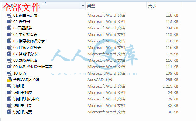
[全部文件] 那张截图中的文件为本资料所有内容,下载后即可获得。
预览截图请勿抄袭,原稿文件完整清晰,无水印,可编辑。
有疑问可以咨询QQ:414951605或1304139763
摘 要
汽车若在冰雪路面或无路的情况下行驶时,就要求增加驱动车轮的数目,以充分利用汽车的重量来增加车轮与道路间的附着力。分动器的主要功用是将发动机输出的动力分配到各驱动桥,并且进一步增大扭矩;其另一个功用是兼起副变速器的作用。分动器也是一个齿轮传动系统,它单独固定在车架上,其输入轴与分动器的输出轴用万向传动装置连接,分动器的输出轴有若干根,分别经万向传动装置与各驱动桥相连。
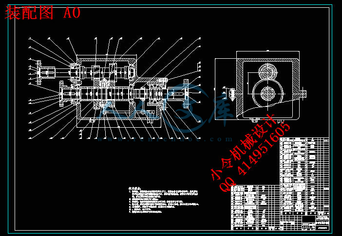
本设计根据匹配车型的使用条件和车辆参数选择分动器的结构形式,并按照分动器总成的设计步骤和要求,对其主要零部件,如齿轮、轴进行了相关的设计工作和校核工作。并根据汽车设计、汽车理论、机械设计、机械设计课程等参考资料提供的相关知识,对计算出的分动器具体参数进行检验,并论证设计的合理性。最终,用AutoCAD软件完成分动器二维装配图和零件图的绘制。
关键词:分动器;分时;中心距;齿轮;轴;结合套
ABSTRACT
If car drive in snow and ice road or no way under the condition of the road, it’s to ask for an increase in the number of driver wheels,To take full advantage of the weight of the car to increase the wheels and the adhesion between road,The main function is to thansfer engine output power distribution to the driving axle, and further increase torque, the other a function is and the deputy variable speed.Thansfer is also a gear transmission system, it alone in frames, the fixed input shaft and thansfer output shaft with universal transmission devices connected, thansfer output shaft several root, the universal respectively with each drive transmission device connected.
This design according to the conditions of use and matching model vehicle parameter selection of structure form, and thansfer according to the design procedures of the assembly thansfer and requirement, for its main parts, such as gear, the shaft related design work and check work. And according to the car design, car theory, mechanical design, mechanical design courses provide reference information for the relevant knowledge, calculated from the concrete parameters for inspection, thansfer and demonstrates the rationality of the design. Finally, with AutoCAD software thansfer 2 d assembly drawings and component drawing.
Key words:Thansfer; points; center distance;Gear;Axis;Meshing sets
目 录
摘要 ………………………………………………………………………………………Ⅰ
Abstract……………………………………………………………………………………Ⅱ
第1章 绪论 ……………………………………………………………………………1
1.1 选题背景 ………………………………………………………………………3
1.2 分动器简介 ……………………………………………………………………3
1.2.1 分动器的类型………………………………………………………………6
1.2.2分动器的构造和原理………………………………………………………4
1.3 分动器的设计思想 ……………………………………………………………… 4
1.4 本设计主要完成的内容 ………………………………………………………… 5
第2章 分动器设计的总体方案 ……………………………………………………6
2.1 分动器结构方案的选择…………………………………………………………6
2.1.1 传动机构布置方案分析…………………………………………………6
2.1.2 零部件结构方案分析………………………………………………………6
2.2设计依据 …………………………………………………………………………8
2.2.1 挡数的确定 ………………………………………………………………9
2.2.2 传动比的确定 ……………………………………………………………9
2.2.3 分动器中心距的确定 ……………………………………………………11
2.3 本章小结 ………………………………………………………………………11
第3章 主要零部件的设计及计算 ………………………………………………13
3.1 齿轮的设计及校核 ……………………………………………………………13
3.1.1 齿轮参数确定及高低挡齿轮齿数分配 …………………………………13
3.1.2 轮齿强度计算……………………………………………………………15
3.1.3 分动器齿轮的材料及热处理……………………………………………17
3.2 轴的设计及校核…………………………………………………………………18
3.2.1 轴的失效形式及设计准则………………………………………………18
3.2.2 轴的设计…………………………………………………………………18
3.2.3 轴的校核…………………………………………………………………19
3.3 轴承的选用及校核………………………………………………………………22
3.3.1 分动器轴承型式的选择…………………………………………………22
3.3.2 轴承的校核………………………………………………………………22
3.3.3 轴承的润滑和密封………………………………………………………24
3.4本章小结………………………………………………………………………24
第4章 分动器其他零件及机构的设计 …………………………………………25
4.1 同步器的设计及计算……………………………………………………………25
4.2 惯性式同步器 ………………………………………………………………… 25
4.2.1锁环式同步器的结构 …………………………………………………… 25
4.2.2锁环式同步器的工作原理 ……………………………………………… 25
4.2.3锁环式同步器主要尺寸的确定 ………………………………………… 27
4.3主要参数的确定 …………………………………………………………………28
4.3.1摩擦因数f …………………………………………………………………28
4.3.2同步环主要尺寸的确定 ………………………………………………… 28
4.3.3锁止角 ………………………………………………………………… 29
4.3.4同步时间 ………………………………………………………………… 30
4.3.5转动惯量的计算 ………………………………………………………… 30
4.4 本章小结………………………………………………………………………… 30
结论 ………………………………………………………………………………………31
参考文献………………………………………………………………………………… 32
致谢 ………………………………………………………………………………………33
附录 ………………………………………………………………………………………34


 川公网安备: 51019002004831号