论文.doc

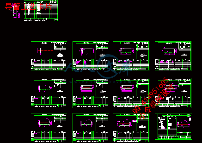
导管注塑模具设计【CAD图纸+WORD毕业论文】【含抽芯结构】

收藏

压缩包内文档预览:(预览前20页/共63页)
预览图 预览图 预览图 预览图 预览图 预览图 预览图 预览图 预览图 预览图 预览图 预览图 预览图 预览图 预览图 预览图 预览图 预览图 预览图 预览图
编号:408808    类型:共享资源    大小:1.14MB    格式:RAR    上传时间:2015-03-03 上传人:好资料QQ****51605 IP属地:江苏
45
积分
关 键 词:
导管 注塑 模具设计 cad 图纸 word 毕业论文 模具
资源描述:

导管注塑模具设计
摘  要
注塑成型是塑件生产最常用的方法之一。本设计通过注塑模具产品,利用实体模型测量产品的尺寸,对实体进行建模,并对塑件的材料和塑件结构进行分析,并对塑件的模具进行设计,包括塑件成品的设计、工艺参数的分析与计算、工作部分的设计、模具结构的设计和加工方案的制定,确定塑件的最佳浇注位置,并通过实际情况进行调整,从而得到对实际生产来说最合理的浇注位置。在确定模具型腔数目后,分析产品的气穴、熔接痕、充填时间、充填结束时的体积温度、流动前沿处的温度、速度/时间转换点压力、充填结束时的压力、注射位置处压力等,可确定注塑模具的合理性。
该模具采用普通浇注系统,由于采用一模两腔的注射结构,必须设置分流道,用点浇口形式从零件端部进料。
此次设计中,最关键的是确定型芯和型腔的结构,此外还分析了模具受力,脱模机构的设计、冷却系统的设计等。

关键词:型腔;熔接痕;分流道;点浇口  


Catheter injection mold design
Abstract
Injection molding is one of the most commonly used method of plastic parts production.This design, injection mold products, measuring the size of the entity model, entity modeling, and materials of plastic parts and plastic parts of the structure of analysis, mold design and plastic parts, including the design of the finished plastic parts,analysis and calculation of the process parameters, the design of the working part of the mold structure design and processing programs to develop, to determine the plastic parts of the casting position and adjust the actual situation, in order to get the most reasonable for the actual production of casting position.Determine the number of mold cavity, the cavitation analysis products, Weld, filling time, filling the end of the volume of temperature at the temperature of the flow front velocity / time conversion point pressure, the pressure in the filling at the end of the injection site at the pressurecan determine the rationality of the injection mold.
The mold using a common gating system, using a two cavity mold injection structure must be set to shunt feed the latent form of point gate from inside the part.
This design, the most critical is to determine the structure of the core and cavity, in addition to analysis of the mold by force, the design of mold release, and the cooling system design.

Key Words:cavity; weld; shunt; point gate

目  录
1绪论 1
1.1 塑料成型与注塑模具 1
1.2 国内外相关发展状况 1
1.2.1国内发展状况 1
1.2.2国外发展状况 2
1.3塑料模具发展走势 2
2塑件材料分析与方案论证 4
2.1塑件的工艺分析 4
2.1.1塑件的材料 4
2.1.2尼龙的基本特性 4
2.1.3尼龙的成型特点 4
2.1.4尼龙的主要用途 5
2.1.5尼龙的注射成型工艺参数 5
2.2 塑件的成型工艺 5
2.2.1注射成型的原理 5
2.2.2注射成型的工艺过程 6
2.2.3注射成型工艺参数 7
2.2.4注塑模的机构组成 8
2.3方案论证 8
3注射成型机的选择 11
3.1估算塑件体积 11
3.2估算塑件质量 11
3.3注塑机的注射容量 11
3.4锁模力 11
3.5选择注塑机及注塑机的主要参数 12
3.5.1注射机的选择 12
3.5.2 XS-ZY-125型注塑机的主要参数 12
3.6注塑机的校核 12
4浇注系统设计 14
4.1浇注系统的功能 14
4.1.1浇注系统的组成 14
4.1.2浇注系统设计原则 14
4.1.3浇注系统布置 14
4.2 流道系统设计 14
4.2.1主流道设计 15
4.2.2冷料井设计 16
4.2.3分流道设计 16
4.2.4浇口设计 17
5成型零件设计 19
5.1分型面的设计 19
5.2成型零件应具备的特能 19
5.3成型零件的结构设计 20
5.3.1凹模(型腔)结构设计 20
5.3.2型芯的结构设计 20
5.4成型零件工作尺寸计算 21
5.4.1影响塑件尺寸和精度的因素 21
5.4.2成型零件工作尺寸的计算 22
5.4.3模具型腔侧壁和底板厚度的计算 23
6导向机构的设计 26
6.1导向机构的作用 26
6.2导柱导向机构 26
6.2.1导向机构的总体设计 26
6.2.2导柱的设计 27
6.2.3导套的设计 27
7脱模机构的设计 28
7.1脱模机构的结构组成 28
7.1.1脱模机构的设计原则 28
7.1.2脱模机构的结构 28
7.1.3脱模机构的分类 28
7.2脱模力的计算 29
7.3简单脱模机构 29
7.3.1推件板脱模机构的设计要点 29
7.3.2推件板的形状 31
7.3.3顶杆强度的计算 31
7.4复位装置 31
8侧向分型与抽芯机构设计 32
8.1侧向分型与抽芯机构的分类 32
8.2斜导柱侧向分型与抽芯机构 32
8.2.1斜导柱侧向分型与抽芯机构设计要点 32
8.2.2斜导柱侧向分型与抽芯机构的工作原理及其类型 33
8.2.3斜导柱抽心距的计算 33
8.2.4开模行程和拉杆尺寸的确定 33
9温度调节系统的设计 35
9.1温度调节系统的作用 35
9.1.1温度调节系统的要求 35
9.1.2温度调节系统对塑件质量的影响 35
9.2冷却系统的机构 36
9.2.1模具冷却系统的设计原则 36
9.2.2模具冷却系统的结构 36
10塑料模具用钢 38
10.1注塑模材料应具备的要求 38
10.2模具材料选用的一般原则 38
10.3本模具所选钢材及热处理 38
11模具工作过程 40
12模具可行性分析 42
12.1本模具的特点 42
12.2市场效益及经济效益分析 42
13总结 43
致谢 44
参考文献 45
毕业设计(论文)知识产权声明 46
毕业设计(论文)独创性声明 47

1  绪论
1.1塑料成型与注塑模具
塑料工业是由塑料原料和塑料制品生产两大系统组成,二者相辅相成,缺一不可,而塑料制品生产是实现塑料原料自身价值的唯一手段。塑料制品生产的目的就是根据各种塑料的性能,利用各种工艺方法,使其成为具有一定形状而又有使用价值的物品或定型材料。塑料制品生产主要由成型、机械加工、表面装饰、装配等环节组成,其重要一环就是塑料成型。
塑料注塑成型过程是,塑料原料从注塑机的料斗进入加热筒,经塑化后由柱塞或螺杆的推动,在一定压力下通过喷嘴进入模具型腔,经冷却固化后而开模获得制品(塑件)。除少数几种塑件外,几乎所有的塑件都可以注塑成型。据有关资料统计,注塑制品占所有模塑件总产量的三分之一;注塑模具占塑料成型模具数量的二分之一以上。注塑成型制品的应用已十分广泛,并随着塑料原料的不断改进,已逐步代替传统的金属和非金属材料的制品,发展注塑模具大有可为。
塑料模具材料直接影响模具的使用寿命﹑加工成本及产品的成型质量,因此设计时要正确地选择模具材料。用于塑料模具材料的品种很多,其中主要是以钢合金工具钢﹑冷﹑热模具钢,不锈钢等,此外,有色金属中有锌合金﹑铝合金﹑铍铜或某些新材料等。随着材料科学不断发展,在模具新材料的应用上,国内外都已经对模具的工作条件,失效形式和提高模具的使用寿命的途径方面进行了大量的研究工作,并开发出许多不仅具有良好的使用性能,而且还有加工好,热处理变形小的新型塑料模具钢,如预硬钢﹑时效硬钢﹑析出硬化钢﹑耐腐蚀钢等,并在生产中得到广泛应用。选择注塑模材料的主要依据是注塑模工作条件,对工作精度要求较低,工作条件比较好的塑料模具,可选择价格较低廉的普通材料制造,而对一些工作精度要求较高,工作条件恶劣的塑料模具,则需要选择价格较贵﹑使用性能好的材料制造。必要时还应对加工好的模具零件进行特殊的强化处理,以使塑料模具有较长的使用寿命。
1.2国内外相关发展状况
1.2.1国内发展状况
模具工业是国民经济发展的重要基础工业,也是一个国家加工工业发展的重要标志。近年来,我国模具工业的技术水平取得了长足的发展。当前,国内已经能生产精度达2微米的的精密多工位级进模,工位数最多已达160个,使用寿命
1-2亿次,大型模具、精密塑料模具和部分汽车覆盖模具都已经达到了很高的水平。
现在,我国模具生产厂点约有3万多家,从业人数80多万人。“十五”期间,模具年平均增长速度达到20%左右,2005年模具销售额达650亿元,同比增长25%;模具出口7.4亿美元,比2004年的4.9亿美元增长约50%,均居世界前列。在模具工业的总产值中,冲压模具约占50%,塑料模具约占33%,压铸模具约占6%,其它各类模具

内容简介:
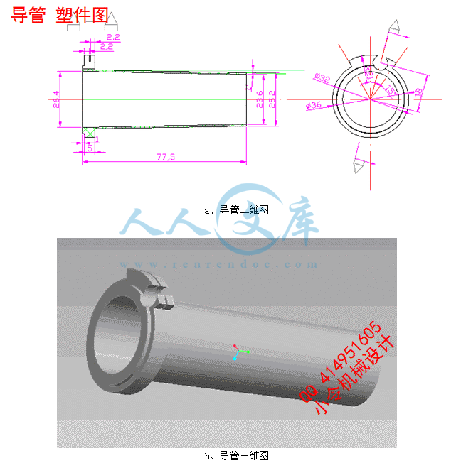
毕业设计(论文)中期报告题目:导管注塑模具设计系 别 机电信息系 专 业 机械设计制造及其自动化 班 级 姓 名 学 号 导 师 2013年 3月 20日1、设计(论文)进展状况本次设计的塑料件为一圆筒形导管,产品特点为:端盖外表面必须光滑,且无明显浇口痕迹;导管底部有一侧抽芯。在结构设计时需考虑型芯在侧抽芯处的脱模,及模具总体结构的合理性。 图1 三维零件图 图2二维零件图1.1在开题的基础上进行了更详细的计算和设计,已优化了结构方案,进一步的完成了模具装配草图的绘制。1.2通过计算塑料件的体积及查阅相关模具设计手册完成了注塑机的选型为:XS-ZY-125型。相关参数如下: 理论注射量: 125cm3 最大注射面积:320cm2 最大模具厚度:300mm 锁模力: 900KN 最小模具厚度:200mm 定位空直径: 100mm 模板行程: 300mm 拉杆空间: 290260mm 喷嘴球半径: 12mm 喷嘴孔径: 4mm1.3确定主流道、分流道的形式和尺寸。其浇口套的尺寸如图3所示。分流道截面形状及尺寸如图4所示。图3浇口套形式与尺寸 图4 分流道截面形状1.4确定模腔数量及其排列方式、浇口形式。导管外形尺寸不大,为了我降低注射成本,根据所选注塑机的注射量,采用一模两腔的模具。为了满足较高的外观要求,确定采用点浇口。其选用的点浇口结构形式如图5所示。图5点浇口结构形式1.5计算并校核型腔部分的强度和刚度,根据导管的高度确定型腔板的侧壁厚度,型芯固定板的厚度。并确动模板、顶出板,支块厚度及其模具安装方法。1.6完成了对模具工作部分尺寸及公差进行设计计算。1.7完成了模具零件结构设计。比如:导柱、导套、拉料杆、复位杆、顶杆、滑块、推板导柱导套等等。1.8初步绘制导管的模具装配图如图6所示。图6 模具装配图1.9绘制了部分零件图。2、 存在问题及解决措施2.1没有将螺钉和弹簧进行安装和校核。解决措施:进行螺钉和弹簧的安装和校核。2.2没有考虑模具在注塑机上的安装。解决措施:查阅相关资料学习安装。2.3中间型芯的固定存在问题,未限制周向转动。解决措施:在老师的指导下,查阅了相关手册,在动模固定板和型芯的交界处安装骑缝螺钉,防止其周向转动。3、 后期工作安排9周12周:完善模具结构装配图,并完成所有零件图的绘制工作,完成模具零件的选材、工艺规程的编制。13周14周:对所有图纸进行校核,编写设计说明书,所有资料提请指导教师检查。15周:准备答辩; 指导老师签字: 年 月 日注:1、正文:宋体小四号字,行距20磅。2、中期报告装订入毕业设计(论文)附件册。Single gate optimization for plastic injection moldLI Ji-quan, LI De-qun, GUO Zhi-ying, LV Hai-yuan(Department of Plasticity Technology, Shanghai Jiao Tong University, Shanghai 200030, China) E-mail: Received Nov. 22, 2006; revision accepted Mar. 19, 2007Abstract: This paper deals with a methodology for single gate lo cation optimization for plastic injection mold. The objective of the gate optimization is to minimize the warpage of injection molded parts, because warpage is a crucial quality issue for most injection molded parts while it is influenced greatly by the gate location. Feature warpage is defined as the ratio of maximum displacement on the feature surface to the projected length of the feature surface to describe part warpage. The optimization is combined with the numerical simulation technology to find the optimal gate location, in which the simulated annealing algorithm is used to search for the optimum. Finally, an example is discussed in the paper and it can be concluded that the proposed method is effective.Key words: Injection mold, Gate location, Optimization, Feature warpage doi: 10.1631/jzus.2007.A1077 Document code: A CLC number: TQ320.66 INTRODUCTION Plastic injection molding is a widely used, complex but highly efficient technique for producing a large variety of plastic products, particularly those with high production requirement, tight tolerance, and complex shapes. The quality of injection molded parts is a function of plastic material, part geometry, mold structure and process conditions. The most important part of an injection mold basically is the following three sets of components: cavities, gates and runners, and cooling system.Lam and Seow (2000) and Jin and Lam (2002) achieved cavity balancing by varying the wall thickness of the part. A balance filling process within the cavity gives an evenly distributed pressure and temperature which can drastically reduce the warpage of the part. But the cavity balancing is only one of the important influencing factors of part qualities. Especially, the part has its functional requirements, and its thicknesses should not be varied usually.From the point view of the injection mold design, a gate is characterized by its size and location, and the runner system by the size and layout. The gate size and runner layout are usually determined as constants. Relatively, gate locations and runner sizes are more flexible, which can be varied to influence the quality of the part. As a result, they are often the design parameters for optimization.Lee and Kim (1996a) optimized the sizes of runners and gates to balance runner system for multiple injection cavities. The runner balancing was described as the differences of entrance pressures for a multi-cavity mold with identical cavities, and as differences of pressures at the end of the melt flow path in each cavity for a family mold with different cavity volumes and geometries. The methodology has shown uniform pressure distributions among the cavities during the entire molding cycle of multiple cavities mold.Zhai et al .(2005a) presented the two gate location optimization of one molding cavity by an efficient search method based on pressure gradient (PGSS), and subsequently positioned weld lines to the desired locations by varying runner sizes for multi-gate parts (Zhai et al ., 2006). As large-volume part, multiple gates are needed to shorten the maxi-mum flow path, with a corresponding decrease in injection pressure. The method is promising for de-sign of gates and runners for a single cavity with multiple gates.Many of injection molded parts are produced with one gate, whether in single cavity mold or in multiple cavities mold. Therefore, the gate location of a single gate is the most common design parameter for optimization. A shape analysis approach was presented by Courbebaisse and Garcia (2002), by which the best gate location of injection molding was estimated. Subsequently, they developed this methodology further and applied it to single gate location optimization of an L shape example (Courbebaisse,2005). It is easy to use and not time-consuming, while it only serves the turning of simple flat parts with uniform thickness.Pandelidis and Zou (1990) presented the optimization of gate location, by indirect quality measures relevant to warpage and material degradation, which is represented as weighted sum of a temperature differential term, an over-pack term, and a frictional overheating term. Warpage is influenced by the above factors, but the relationship between them is not clear. Therefore, the optimization effect is restricted by the determination of the weighting factors.Lee and Kim (1996b) developed an automated election method of gate location, in which a set of initial gate locations were proposed by a designer and hen the optimal gate was located by the adjacent node evaluation method. The conclusion to a great extent depends much on the human designers intuition, because the first step of the method is based on the designers proposition. So the result is to a large extent limited to the designers experience.Definition of feature warpage To apply optimization theory to the gate design, quality measures of the part must be specified in the first instance. The term “quality” may be referred to many product properties, such as mechanical, thermal, electrical, optical, ergonomical or geometrical properties. There are two types of part quality measures: direct and indirect. A model that predicts the proper-ties from numerical simulation results would be characterized as a direct quality measure. In contrast, an indirect measure of part quality is correlated with target quality, but it cannot provide a direct estimate of that quality.For warpage, the indirect quality measures in related works are one of performances of injection molding flowing behavior or weighted sum of those. The performances are presented as filling time differential along different fl ow paths, temperature differential, over-pack percentage, and so on. It is obvious that warpage is influenced by these performances, but the relationship between warpage and these performances is not clear and the determination of these weighting factors is rather difficult. Therefore, the optimization with the above objective functionprobably will not minimize part warpage even with perfect optimization technique. Sometimes, improper weighting factors will result in absolutely wrong results.In industry, designers and manufacturers usually pay more attention to the degree of part warpage on some specific features than the whole deformation of the injection molded parts. In this study, feature warpage is defined to describe the deformation of the injection parts. The feature warpage is the ratio of the maximum displacement of the feature surface to the projected length of the feature surface (Fig.1): =% (1)where is the feature warpage, h is the maximum displacement on the feature surface deviating from the reference platform, and L is the projected length of the feature surface on a reference direction paralleling the reference platform.Evaluation of feature warpageAfter the determination of target feature combined with corresponding reference plane and projection direction, the value of L can be calculated immediately from the part with the calculating method of analytic geometry (Fig.2). L is a constant for any part on the specified feature surface and projected direction. But the evaluation of h is more complicated than that of L.Simulation of injection molding process is a common technique to forecast the quality of part design, mold design and process settings. The results of warpage simulation are expressed as the nodal deflections on X, Y , Z component ( W x, Wy, Wz), and the nodal displacement W . W is the vector length of vector sum of W x i, Wy j , and Wz k, where i , j , k are the unit vectors on X , Y , Z component. The h is the maximum displacement of the nodes on the feature surface, which is correlated with the normal orientation of the reference plane, and can be derived from the results of warpage simulation.To calculate h , the deflection of Ith node is evaluated firstly as follows:where Wi is the deflection in the normal direction of the reference plane of ith node; Wix, Wiy, Wiz are the deflections on X , Y , Z component of ith node; , , are the angles of normal vector of the reference; A and B are the terminal nodes of the feature to projecting direction (Fig.2); W A and W Bare the deflections of nodes A and B .APPLICATION AND DISCUSSION The application to a complex industrial part is presented in this section to illustrate the proposed quality measure and optimization methodology. The part is provided by a manufacturer, as shown in Fig 4. In this part, the flatness of basal surface is the most important profile precision requirement. Therefore, the feature warpage is discussed on basal surface, in which reference platform is specified as a horizontal plane attached to the basal surface, and the longitudinal direction is specified as projected reference direction. The parameter h is the maximum basal surface deflection on the normal direction, namely the vertical direction, and the parameter L is the projected length of the basal surface to the longitudinal direction.The material of the part is Nylon Zytel 101L (30% EGF, DuPont Engineering Polymer). The molding conditions in the simulation are listed in Table 1. Fig . 5 shows the finite element mesh model of the part employed in the numerical simulation. It has 1469 nodes and 2492 elements. MPI is the most extensive software for the injection molding simulation, which can recommend the best gate location based on balanced flow. Gate location analysis is an effective tool for gate location design besides empirical method. For this part, the gate location analysis of MPI recommends that the best gate location is near node N7459, as shown in Fig.5. The part warpage is simulated based on this recommended gate and thus the feature warpage is evaluated: =5.15%, which is a great value. In trial manufacturing, part warpage is visible on the sample work piece. This is unacceptable for the manufacturer.The great warpage on basal surface is caused by the uneven orientation distribution of the glass fiber, as shown in Fig.6a. Fig.6a shows that the glass fiber orientation changes from negative direction to positive direction because of the location of the gate, particularly the greatest change of the fiber orientation appears near the gate. The great diversification of fiber orientation caused by gate location introduces serious differential shrinkage. Accordingly, the feature warpage is notable and the gate location must be optimized to reduce part warpage.To optimize the gate location, the simulated annealing searching discussed in the section “Simulated annealing algorithm” is applied to this part. The maximum number of iterations is chosen as 30 to ensure the precision of the optimization, and the maximum number of random trials allowed for each iteration is chosen as 10 to decrease the probability of null iteration without an iterative solution. Node N7379 (Fig.5) is found to be the optimum gate location. The feature warpage is evaluated from the warpage simulation results f (X)= =0.97%, which is less than that of the recommended gate by MPI. And the part warpage meets the manufacturers requirements in trial manufacturing. Fig.6b shows the fiber orientation in the simulation. It is seen that the optimal gate location results in the even glass fiber orientation, and thus introduces great reduction of shrinkage difference on the vertical direction along the longitudinal direction. Accordingly, the feature warpage is reduced.CONCLUSION Feature warpage is defined to describe the warpage of injection molded parts and is evaluated based on the numerical simulation software MPI in this investigation. The feature warpage evaluation based on numerical simulation is combined with simulated annealing algorithm to optimize the single gate location for plastic injection mold. An industrial part is taken as an example to illustrate the proposed method. The method results in an optimal gate location, by which the part is satisfactory for the manufacturer. This method is also suitable to other optimization problems for warpage minimization, such as location optimization for multiple gates, runner system balancing, and option of anisotropic materials. REFRENCES Courbebaisse, G., 2005. Numerical simulation of injection moulding process and the pre-moulding concept. Computational Materials Science , 34(4):397-405. doi:10.1016/matsci.2004.11.004 Courbebaisse, G., Garcia, D., 2002. Shape analysis and injection molding optimization. Computational Materials Science,25(4):547-553. doi:10.1016/S0927-0256(02) 00333-6 Jin, S., Lam, Y.C., 2002. 2.5D cavity balancing. Journal of Injection Molding Technology, 6(4):284-296. Kirkpatrick, S., Gerlatt, C.D.Jr., Vecchi, M.P., 1983. Optimiza- tion by simulated annealing. Science, 220 (4598):671-680. doi:10.1126/science.220.4598.671 Lam, Y.C., Seow, L.W., 2000. Ca vity balance for plastic injection molding. Polymer Engineering and Science, 40(6):1273-1280. doi:10.1002/pen.11255 Lam, Y.C., Jin, S., 2001. Opti mization of gate location for plastic injection molding. Journal of Injection Molding Technology , 5(3):180-192. Lee, B.H., Kim, B.H., 1995. Optimization of part wall thicknesses to reduce warpage of injection-molded parts based on the modified complex method. Polymer-Plastics Technology and Engineering , 34(5):793-811. Lee, B.H., Kim, B.H., 1996a. Automated design for the runner system of injection molds based on packing simulation. Polymer-Plastics Technology and Engineering , 35(1): 147-168. Lee, B.H., Kim, B.H., 1996b. Automated selection of gate location based on desired qualit y of injection molded part. Polymer-Plastics Technology and Engineering , 35(2): 253-269. Metropolis, N., Rosenbluth, A.W., Rosenbluth, M.N., Teller, A.H., Teller, E., 1953. Equations of state calculations by fast computing machines. Journal of Chemical Physic s, 21(6):1087-1092. doi:10.1063/1.1699114 Pandelidis, I., Zou, Q., 1990. Optimization of injection molding design Part I: gate location optimization. Polymer Engineering and Science, 30(15):873-882. doi:10.1002/ pen.760301502 Pincus, M., 1970. A Monte Carl o method for the approximate solution of certain types of constrained optimization problems. Operations Research, 18:1225-1228. Shen, C.Y., Yu, X.R., Wang, L.X., Tian, Z., 2004a. Gate location optimization of plastic injection molding. Journal of Chemical Industry and Engineering , 55(3):445-449 (in Chinese). Shen, C.Y., Yu, X.R., Li, Q., Li, H.M., 2004b. Gate location optimization in injection molding by using modified hill-climbing algorithm. Polymer-Plastics Technology and Engineering, 43(3):649-659. doi:10.1081/PPT- 120038056 Zhai, M., Lam, L.C., Au, C.K., 2005a. Algorithms for two gate optimization in injection molding. International Polymer Processing, 20(1):14-18. Zhai, M., Lam, L.C., Au, C.K., Liu, D.S., 2005b. Automated selection of gate location for plastic injection molding processing. Polymer-Plastics Technology and Engineering , 44(2):229-242. Zhai, M., Lam, L.C., Au, C.K., 2006. Runner sizing and weld line positioning for plastics injection molding with multiple gates. Engineering with Computers, 21(3): 218-224. doi:10.1007/s00366-005-0006-6单一的塑料注塑模具浇口的优化李集泉,立德群,郭志颖,吕海元(塑性技术系,上海交通大学,上海200030,中国)电子邮件:2006年11月22日收到 2007年3月19日修改接受;摘要:本文对单一浇口注塑模具的优化方法进行分析。浇口的优化目标是最小化注塑件翘曲变形,因为对于大多数注塑件是一个关键的质量问题,它是受浇口位置的影响很大。特征翘曲度被定义为最大位移特征表面上的投影长度的比值来描述零件翘曲。最好的优化方法是与数值模拟技术相结合,找到最佳的浇口位置,其中以模拟退火算法是用来寻找最佳。最后,用一实例说明了用平面特征上的翘曲度评价翘曲变形的有效性。关键词:注塑成形,浇口位置,优化,特征翘曲度DOI:10.1631/jzus.2007.a1077文献标识码:A中图分类号:tq320.66引言塑料注射成型是一种广泛使用的,复杂的但高效生产大量各种塑料制品的技术,特别是用于生产那些生产要求高,精度高,和复杂形状的塑件。注塑件的质量是由塑料材料,零件的几何形状,模具结构和工艺条件决定的。注塑模具的最重要的组成部分,主要是以下三部分组成:形腔,浇口,流道,和冷却系统。Lam,Seow(2000)和Lam(2002)通过改变形腔的部分壁厚达到平衡。一个平衡充填过程的空腔内均匀分布的压力和温度,可大大减少塑件热变形。但形腔平衡是影响部分质量的重要因素。特别是部分有其功能要求,其厚度通常不应改变。 从模具设计的角度来看,一个浇口的特点是由它的大小,位置,和浇注系统的尺寸和布局决定。浇口尺寸、流道布局通常确定为常数。相对而言,浇口位置、流道尺寸更灵活,可以多种多样来影响零件的质量。因此,他们通常是优化设计的参数。Lee和Kim(1996)优化流道和浇口的尺寸为多点喷射腔浇注系统的平衡。流道平衡被描述为一个具有相同的腔模多腔入口压力的差异,在熔体的流动路径中的每个腔不同空腔体积和几何形状的一个底模压力存在差异。在多腔模具整个成型周期中,该方法已显示出空腔中的压力可以均匀分布。翟等人(2005年)提出了同一个压力梯度的基础上成型腔的两个浇口位置优化的搜索方法(PGSS),并随后通过改变流道尺寸多闸部件定位焊线到所需的位置(翟等人。2006年)。体积大的部分,在注射压力相应减小的同时,多浇口需要缩短最大流道。该方法是有前途的单腔多浇口和流道设计。许多注塑件无论是在单型腔或多腔模具是单浇口生产,。因此,一个单一浇口的位置优化是最常见的设计参数。形状分析方法是通过courbebaisse和加西亚提出的(2002年),来确定注射成型最佳浇口位置。随后,他们改善了这一方法,进一步应用到一个L形如单浇口位置优化(courbebaisse,2005)。这是易于使用和不费时的,而它仅是简单的平面部分厚度的均匀过度。Landslides和邹(1990年)提出的浇口位置的优化,以解决变形过大和过热降解问题,这是代表一个温度微分项的加权总和,一组参
温馨提示:
1: 本站所有资源如无特殊说明,都需要本地电脑安装OFFICE2007和PDF阅读器。图纸软件为CAD,CAXA,PROE,UG,SolidWorks等.压缩文件请下载最新的WinRAR软件解压。
2: 本站的文档不包含任何第三方提供的附件图纸等,如果需要附件,请联系上传者。文件的所有权益归上传用户所有。
3.本站RAR压缩包中若带图纸,网页内容里面会有图纸预览,若没有图纸预览就没有图纸。
4. 未经权益所有人同意不得将文件中的内容挪作商业或盈利用途。
5. 人人文库网仅提供信息存储空间,仅对用户上传内容的表现方式做保护处理,对用户上传分享的文档内容本身不做任何修改或编辑,并不能对任何下载内容负责。
6. 下载文件中如有侵权或不适当内容,请与我们联系,我们立即纠正。
7. 本站不保证下载资源的准确性、安全性和完整性, 同时也不承担用户因使用这些下载资源对自己和他人造成任何形式的伤害或损失。
提示  人人文库网所有资源均是用户自行上传分享,仅供网友学习交流,未经上传用户书面授权,请勿作他用。
关于本文
本文标题:导管注塑模具设计【CAD图纸+WORD毕业论文】【含抽芯结构】
链接地址:https://www.renrendoc.com/p-408808.html

官方联系方式

2:不支持迅雷下载,请使用浏览器下载   
3:不支持QQ浏览器下载,请用其他浏览器   
4:下载后的文档和图纸-无水印   
5:文档经过压缩,下载后原文更清晰   
关于我们 - 网站声明 - 网站地图 - 资源地图 - 友情链接 - 网站客服 - 联系我们

网站客服QQ:2881952447     

copyright@ 2020-2025  renrendoc.com 人人文库版权所有   联系电话:400-852-1180

备案号:蜀ICP备2022000484号-2       经营许可证: 川B2-20220663       公网安备川公网安备: 51019002004831号

本站为文档C2C交易模式,即用户上传的文档直接被用户下载,本站只是中间服务平台,本站所有文档下载所得的收益归上传人(含作者)所有。人人文库网仅提供信息存储空间,仅对用户上传内容的表现方式做保护处理,对上载内容本身不做任何修改或编辑。若文档所含内容侵犯了您的版权或隐私,请立即通知人人文库网,我们立即给予删除!