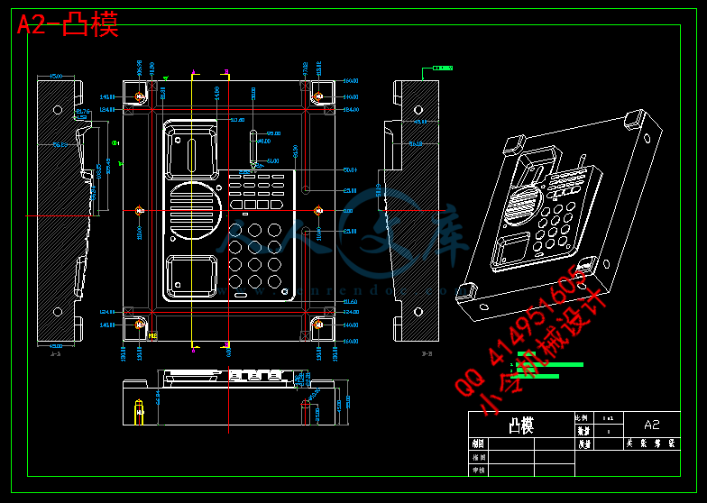
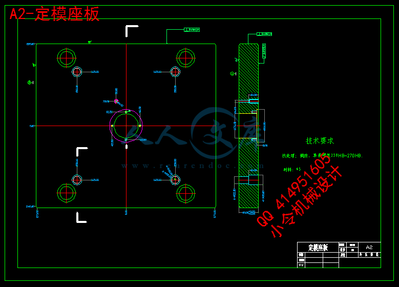
答辩PPt.ppt

电话机外壳注射模模具设计-电话面板注塑模【11张CAD图纸+答辩PPT+论文】【注塑模具类】

收藏

资源目录
跳过导航链接。
压缩包内文档预览:(预览前20页/共28页)
预览图 预览图 预览图 预览图 预览图 预览图 预览图 预览图 预览图 预览图 预览图 预览图 预览图 预览图 预览图 预览图 预览图 预览图 预览图 预览图
编号:408817    类型:共享资源    大小:6.60MB    格式:RAR    上传时间:2015-03-03 上传人:好资料QQ****51605 IP属地:江苏
45
积分
关 键 词:
电话机 外壳 注射 模具设计 cad 图纸 word 毕业论文 注塑 模具
资源描述:

【温馨提示】 购买原稿文件请充值后自助下载。

[全部文件] 那张截图中的文件为本资料所有内容,下载后即可获得。


预览截图请勿抄袭,原稿文件完整清晰,无水印,可编辑。

有疑问可以咨询QQ:414951605或1304139763

摘要

  本次毕业设计任务是完成电话机外壳的一模一腔注塑模具设计。根据塑件的结构、技术要求及企业生产的实际情况,和应用三维设计软件Pro/E进行电话机外壳的注射模设计。本设计分析塑件的工艺性,设计了塑件的注塑模具结构,并通过型腔压力和锁模力的计算,选择注塑机,给出了相关工艺参数。分别对浇注系统、分型面的选取、脱模推出机构设计、冷却结构设计、等进行了介绍。为降低模具成本,提高生产效率, 对于有国家标准的零部件,本设计均采用标准件,其中包括:注塑模标准模架;标准导柱、导套等。对于有推荐尺寸的零件,均选用推荐值设计,如浇口套等。

  关键词:注射模 分型面 冷却结构 推出机构


Abstract

  The graduation task is to design a complete telephone shell of a cavity-injection mold design. According to the structure of plastic parts, technical requirements and the actual situation of production, and 3-D design software Pro / E for the phone casing injection mold design. The design of plastic parts of the process, the design of plastic parts injection mold structure, and through the cavity pressure and the clamping force, the choice of injection molding machine, given the relevant technical parameters. Pouring on the respective systems, sub-surface selection, introduction agencies Stripping design, cooling structural design, etc. were introduced. To reduce die costs, increase productivity, for a national standard parts, the design of a standard parts, including: injection mold-standard mode; standards-guided, guided sets, and so on. The recommended size of the parts are optional recommended design, such as gate sets

  Keywords:Injection Mould         Sub-surface  
Cooling structure      Introduction  agencies


目录
摘要 I
Abstract II
第一章  塑件的成形工艺性分析 1
1.2 ABS的注射成型工艺 1
1.3 ABS性能分析 2
1.4 ABS成型塑件的主要缺陷及消除措施: 3
第二章   注塑机的确定 4
2.1 有关塑件的计算 4
2.2 注射机型号的确定 4
2.3 注射机有关工艺参数的校核 4
第三章    分型面位置的确定 7
3.1 分型面的形式 7
3.2 分型面的设计原则 7
第四章  模型腔排列方式的确定 8
4.1 确定型腔数量及排列方式 8
第五章    注射模浇注系统的设计 9
5.1 对浇注系统进行整体设计时,一般应遵循如下基本原则: 9
5.2 主流道的设计 9
5.3 分流道的设计 10
第六章  注射成型零件设计 13
6.1 成型零件的选材 13
6.2 凹模部分的结构设计 14
6.3 凸模部分的结构设计 16
第七章   脱模推出机构的设计 18
7.1 推出机构的设计要求 18
7.2 脱模阻力计算 18
第八章  模架的确定和标准件的选用 20
8.1 定模固定板(定模座板)(500550,厚60mm) 20
8.2 定模板(500450,厚90mm) 20
8.3 动模固定板(500550,厚35mm) 20
8.4 动模板(500450,厚100mm。) 20
8.5 推杆固定板(290496,厚25mm) 20
8.6 推板(290496,厚25mm) 20
第九章   设计总结 21
致谢 22
参考文献 23


第一章  塑件的成形工艺性分析
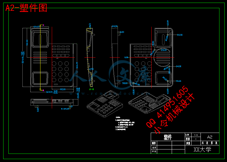
1、塑件(电话机外壳)模型图:

 塑件图
2、塑件材料的选择:选用ABS(即丙烯腈-丁二烯-苯乙烯共聚物)。
3、色调:黑色。
4、生产批量:中批量。
5、塑件的结构与工艺性分析:
(1)结构分析
塑件为电话机外壳的上半部分,应有一定


内容简介:
Materials Science and Engineering A 444 (2007) 99103Semisolid microstructure of Mg2Si/Al composite by cooling slopecast and its evolution during partial remelting processQ.D. Qin, Y.G. Zhao, P.J. Cong, W. Zhou, B. XuKey Laboratory of Automobile Materials of Ministry of Education and Department of Materials Science & Engineering,Jilin University, No. 142 Renmin Street, Changchun 130025, PR ChinaReceived 17 April 2006; accepted 15 August 2006AbstractAn in situ Mg2Si/AlSiCu composite with semisolid structure was fabricated by cooling slope cast and partial remelting process. The as-castmicrostructure, and effect of isothermal holding time on the morphology, size and shape factor of the grains were investigated. The results showthat the morphology of primary Mg2Si and ?-Al grains in the composite are globular and/or elliptic after partial remelting process. The size andshape factor of ?-Al grains increase with the isothermal holding time. 2006 Elsevier B.V. All rights reserved.Keywords: Semisolid; Aluminum; Composites; Microstructure; Magnesium silicide1. IntroductionIt has been well known that semisolid processing (SSP) has alot of significant advantages over conventional casting, such asminimizing the macrosegregation and solidification shrinkageand reducing the forming temperature. The key that permits thesemisolidalloystoshapeistheabsenceofdendriticmorphologyof the solid phase 1. The typical non-dendritic microstruc-ture needed is constituted of solid phase globules suspended inthe liquid phase. The thixotropic effect of the semisolid alloysallows them to be handled as a massive solid and to attain fluid-like properties when sheared during shaping 2. Many differentroutes have been used to produce non-dendritic microstructure,such as magnetohydrodynamic (MHD) stirring, spray forming,strain induced melt activated (SIMA)/recrystallisation and par-tial melting (RAP), liquidus/near-liquidus casting etc. 38.Recently, Czerwinski 911 investigated the fabrication ofsemisolid Mg alloys components by injection molding process.Kleineretal.12studiedtheformationofsemisolidMgAlZnalloybyextrudedmethod.Wuetal.13constructedamodelongrowthmorphologyofsemisolidmetals,usingsolidificationandflow speed of the liquid as variations affecting the morphologyof crystals. Among all the techniques of SSP, the cooling slopeCorresponding author. Tel.: +86 431 509 4481; fax: +86 431 509 5592.E-mail address: (Y.G. Zhao).process is a simple route. The primary phase in the semisolidalloy by the cooling slope cast has been reported to becomespherical after remelted in the semisolid state 14. Haga andSuzuki 14,15 investigated the producing process of ingots forthixoforming of Al6Si alloys by cooling slope casting.HypereutecticAlSialloyswithhighMgcontentisinfactanin situ aluminum matrix composites containing a large amountof hard particles of Mg2Si, and the Mg2Si/Al composite has apotential as automobile brake disc material because the inter-metallic compound of Mg2Si exhibits has high melting tem-perature, low density, high hardness, low thermal expansioncoefficient and reasonably high elastic modulus 8. However,the coarse reinforcement of the primary Mg2Si particles in thenormal composite leads to poor properties. Therefore, the com-posite with coarse primary Mg2Si particles need to be modifiedtoobtainadequatemechanicalstrengthandductility.Ithasbeenreported that rare earth elements such as Ce 16, Sr 17 andits salts 18,19 have the power to modify the morphology ofprimary Mg2Si. A semisolid microstructure in the composite isexpected to improve the mechanical properties. The semisolidof Mg2Si/Al composite has been produced via SIMA in pre-vious study 8. However, this technology is relative complexbecause of requiring cold extrusion and deformation. Less workhas been carried out on semisolid Mg2Si/Al composite by thecooling slope cast and partial remelting process. In the presentstudy, a semisolid of in situ Mg2Si/AlSiCu composite waspreparedbythecoolingslopecastandpartialremeltingprocess,0921-5093/$ see front matter 2006 Elsevier B.V. All rights reserved.doi:10.1016/j.msea.2006.08.074100Q.D. Qin et al. / Materials Science and Engineering A 444 (2007) 99103Table 1Chemical compositions of the Mg2Si/Al composite (wt.%)MaterialsAlMgSiCuCrZnNiFeAlSiMgCuBal.13.27611.2813.5230.0050.02399.7% purity) and magnesium (ingot, 98.0% purity)were used to prepare the experimental alloy. About 520g ofAlSi master alloy melt was molten in a graphite crucible in anelectric resistance furnace. About 100g of magnesium and 26gof Cu, preheated at 300C, were added into the AlSi melt at680700C. After holding 15min, the melt were poured into asteelmoldviaaaluminumcoolingslope(preheatedat300C)toproduce the in situ Mg2Si/Al composite ingots, and the chem-ical compositions are listed in Table 1. The schematic of thecasting process is shown in Fig. 1 (adopted from 15). Sub-sequently, the ingot was cut into a series of cubic samples of12mm12mm12mm. The partial remelting process wasperformedinaverticaltubefurnace,andthesampleswereheatedup to 560C and held at the temperature for 30, 60, 180 and600min, respectively, and then were quenched in cold water.Metallographic specimens were polished through standardprocedure and the microstructure in them examined using anoptical microscopy. A 0.5% hydrofluoric acid (HF) aqueoussolution was used as the etchant of polishing samples. The grainsize and area of the primary solid phase were analyzed sta-tistically by a quantitative analysis system (Omnimet ImagingSystems-Buehler, USA).3. Results and discussionAccording to the composition of the alloy and the previousstudies 8,16, the as-cast microstructure of the composite con-sists of Mg2Si, ?-Al and eutectic Si phases. Fig. 2a and b showsthe typical as-cast microstructure of in situ Mg2Si/Al compos-ite by the normal cast and cooling slope cast, respectively. Themicrostructure of the composite reveals that the morphology ofprimary Mg2Si as-cast in the composite by the normal cast wasdendritic (as indicated with a arrow in Fig. 2a), with a size of200?m,andthe?-Alwasdendriticaswell.However,afterthecomposite solid with the cooling slope, the morphology of ?-Alphase in the composite by the cooling slop cast changes fromdendritictospheralwithadiameterof10?m,andtheprimaryMg2Si crystals become fine obviously, as seen in Fig. 2b. Onereason for it is due to the increase in the nucleation substratesin the melt after casting with the cooling slope; another reasonis related to the flow of the melt on the slope. The flowing meltwill cause partial fragments of the dendrites of the dendrites byconvection.Fig. 3ad shows the evolution of the semisolid microstruc-tures of the composite by the cooling slope cast with theholding time of isothermal heat treatment of 30, 60, 180 and600min, respectively. Fig. 3a shows that the as-cast coarseMg2Si dendrites are fragmented, changing to an irregularshape, with slightly rounded tips, and the morphology of ?-Alhave becomes globular with a mean size of 51?m. As theholding time increases to 60min, the morphology of the Mg2Siparticlesinthecompositebecomesmainlyellipticshapeandthemorphology of ?-Al becomes more globular with a mean sizeof85?mseeninFig.3b.Furthermore,italsoshowsthatsomesmaller ?-Al grains is not dissolved completely surviving in theliquid, as indicated by white arrows in Fig. 3b. Fig. 3c shows theFig. 2. As-cast microstructures of Mg2Si/Al composites by (a) the normal cast (adopted from 8) and (b) the cooling slope cast.Q.D. Qin et al. / Materials Science and Engineering A 444 (2007) 99103101Fig. 3. Semisolid microstructures of the Mg2Si/Al composite by the cooling slope cast with different isothermal holding time of (a) 30min, (b) 60min, (c) 180minand (d) 600min.microstructure of the composite with a isothermal treatment for180min. The morphologies of the Mg2Si and ?-Al particles donot change obviously, however, the mean size of ?-Al particlesincreasesto111?m.Itisofinteresttonotethatsome“smallergrains” emerge on the surface of the large globular grains of?-Al, as indicated by black arrows in Fig. 3c. The amount of thesurvived small solid particles increases, in comparison with thatof60minholdingtime.Itseemsthattheliquidfractionincreasesaswell.Unfortunately,theliquidfractioncouldnotbemeasuredin the present study, because of the survived of the small solidparticles. Poirier et al. 20 reported that the volume fraction ofliquidofAlCualloyslightlydecreasedatthecoarseningperiodduring semisolid isothermal treatment. The phenomenon needsfurther study. Fig. 4a shows that the morphology of the “smallergrains”iscolumnarandsomesurvivedsolidphasesareirregularshapeasdenotedbythewhitearrowinFig.4a.Astheisothermaltreatment time increases up to 600min, the morphologies ofthe primary Mg2Si particles and ?-Al grains are still globular,as shown in Fig. 3d. The size of the ?-Al grains increaseobviously with a mean size of 149?m. In addition, the amountof the survived solid particles evidently decreases, and the“smaller grains” on the surface of large ?-Al grains disappear.The “smaller grains” emergence may be the consequence ofsolidificationoftheliquidduringhandlingofthesamplesbeforequenching in water, and that emergence and disappearancemay be due to the difference of the handle time for quenching.From Fig. 4b, it is clearly indicated that the morphologies ofthe survived solid particles do not change obviously.To get better understanding of the evolution of the solid par-ticles is of important, because it determines the final grain sizeof the composite, and thus the mechanical properties 21. Theformation of a semisolid structure by isothermal holding from aFig. 4. Metallographs of the composites with the isothermal time of (a) 180min and (b) 600min, showing the ?-Al “smaller grains”.102Q.D. Qin et al. / Materials Science and Engineering A 444 (2007) 99103Fig. 5. The relationship of the mean size of ?-Al grains and the holding time.conventionally cast dendritic structure has been studied earlier8. The transition of the solid phase from dendritic into spheralis thought to be due to the liquid penetration, namely, the as-cast grain boundary is penetrated by liquid during the semisolidisothermal holding, causing the fragmentation of the dendritearms and then, the fragmented arms change into spheroidal orellipsoidal grains.The relationship between the grain size of the ?-Al particlesand holding time is shown in Fig. 5. The size of the ?-Al parti-clesincreaseswiththeholdingtime.Onecoarseningmechanismis the coalescence of the grains, namely, two grains encounterjoining together and forming new bigger grain 22. AnothercoarseningmechanismistheOstwaldripening22,23,inwhichthe larger grains grow and the smaller grains remelt.Using the image analysis system, the number of the objectsin a selected area, and the perimeter and area of selected objectscan be measured 2. Normally, the shape of an object is char-acterized by the shape factor F0defined as 2:F0=4A0P20(1)where A0and P0represent the area and perimeter of the object,respectively 2. The change of the shape factor during theisothermal treatment is shown in Fig. 6. It is indicated that theshapefactorincreasesrapidlyfrom0.51to0.69withtheholdingtime from 30 to 180min and however, a much larger holdingtime cannot result in a considerable change of F0, suggestingthat the F0seems to reach to a maximum value. It is reportedthat the solid phase particles tend to become spherical, but, fora longer holding time, the change of the shape of the particlesslows down and even reverses in the case of the high values ofsolid volume fraction 21. Keeping in mind that the high solidvolumefractionmeansalsoahighcontiguity,thisreversionfromthe spherical shape can be attributed to the hard impingementof the solid particles, leading to the local shape distortions 21.In the present study, however, the solid volume fraction in themicrostructuresislowerrelatively(0.6)accordingtotheresultof the quantitative analysis, and consequently, the chance of thehard impingement is lower as well. With increase in the hold-Fig. 6. Relationship of the shaper factor of the ?-Al grains ant the holding time.ing time, the higher curvature part of the solid particle will bedissolved, and leading to the increase of the F0. Finally, the pro-cess reaches to a dynamic equilibrium and the shape factor ofthe grains will not change.4. ConclusionThe semisolid structure of in situ Mg2Si/Al composite issuccessfully produced by the cooling slope cast and partialremelting process. The results show that: (a) the morphologyof primary Mg2Si phase is globular and/or elliptic not changingobviously with increase in the isothermal holding time; (b) withincrease in the isothermal holding time from 30 to 600min, themean size of ?-Al grains increases from 50 to 150?m, and itsmorphology becomes more globular; (c) the shape factor of the?-Al solid particles rapidly from 0.51 to 0.69 with the holdingtime from 30 to 60min.AcknowledgementsThisworkissupportedbyTheProject985-AutomotiveEngi-neering of Jilin University and The Innovation and InventionFoundation of Jilin University (2003CX029).References1 E. Tzimas, A. Zavaliangos, Mater. Sci. Eng. A 289 (2000) 217.2 W.R. Loue, M. Suery, Mater. Sci. Eng. A 203 (1995) 1.3 H.V. Atkinson, Prog. Mater. Sci. 50 (2005) 341.4 M.P. Kenney, J.A. Courtois, R.D. Evans, G.M. Farrior, C.P. Kyonka, A.A.Koch,K.P.Young,MetalsHandbook,vol.15,19thed.,ASMInternational,Metals Park, OH, USA, 1988, p. 327.5 P.J. Ward, H.V. Atkinson, P.R.G. Anderson, L.G. Elias, B. Garcia, L.Kahlen, J.M. Rodriguez-Ibade, Acta Mater. 44 (1996) 1717.6 K.P. Young, C.P. Kyonka, J.A. Courtois, Fine grained metal composition,US Patent no. 4,414,374 (30 March 1982).7 European Patent 0745694A1, Method and apparatus of shaping semisolidmetals, UBE Industries Ltd. (1996).8 Q.D. Qin, Y.G. Zhao, K. Xiu, W. Zhou, Y.H. Liang, Mater. Sci. Eng. A 407(2005) 196.9 F. Czerwinski, Acta Mater. 53 (2005) 1973.10 F. Czerwinski, Mater. Sci. Eng. A 392 (2005) 51.Q.D. Qin et al. / Materials Science and Engineering A 444 (2007) 9910310311 F. Czerwinski, Int. Powder Met. 41 (2005) 64.12 S. Kleiner, O. Beffort, P.J. Uggowitzer, Scr. Mater. 51 (2004) 405.13 S.S. Wu, X.P. Wu, Z.H. Xiao, Acta Mater. 52 (2004) 3519.14 T. Haga, S. Suzuki, J. Mater. Process. Technol. 118 (2001) 169.15 T. Haga, J. Mater. Process. Technol. 130131 (2002) 558.16 Y.G. Zhao, Q.D. Qin, W. Zhou, Y.H. Liang, J. Alloys Compd. 389 (2005)L1.17 Y.G. Zhao, Q.D. Qin, Y.H. Liang, W. Zhou, Q.C. Jiang, J. Mater. Sci. Lett.40 (2005) 1831.18 Y.G. Zhao, Q.D. Qin, Y.Q. Zhao, Y.H. Liang, Q.C. Jiang, Mater. Lett. 58(2004) 2192.19 J. Zhang, Z. Fan, Y. Wang, B. Zhou, J. Mater. Sci. Lett. 18 (1999)783.20 D.R. Poirier, S. Ganesan, M. Andres, P. Ocansey, Mater. Sci. Eng. A 148(1991) 289.21 M. Ferrante, E. Freitas, Mater. Sci. Eng. A 271 (1999) 172.22 J.L. Wang, Y.H. Su, C-Y.A. Tsao, Scr. Mater. 37 (1997) 2003.23 M.C. Flemings, Metall. Trans. A 22A (1997) 957.复合材料mg2si/al的冷却斜槽法铸造和其局部重熔演化过程中的半固态微观结构摘要Mg2Si/AlSiCu 复合材料的半固态结构及斜槽铸造的部分重熔过程。该铸态微观结构的形态,大小和形状受保温时间等的因素影响。据调查结果表明:该 mg2si和- Al晶粒部分重熔过程后形态的主要呈复合球形和椭圆形。Al晶粒大小和形状因子- 与保温时间长短有关。1 。导言众所周知,半固态加工( SSP )的有很多显着的优势,与传统的铸造相比它尽量减少宏观偏析、凝固收缩和形成温度。关键该固相 1 半固态合金的形成是由于缺乏树突状形态 。典型的非树突状的微观结构需要的是构成固相球悬浮在液相。触变的影响,该合金半固态使他们能够处理大量固体。许多不同的路线已被用来生产非树突状结构, 如磁流体(磁流体)搅拌,喷射成形, 应变诱导熔体激活结晶和部分熔化( RAP )的液相/近液相线铸造等 3-8 。 最近,切尔文斯基 9月11日调查的制作镁合金半固态组件的注塑成型过程。 菲尔德等人 12 研究形成的半固态镁-铝-锌合金挤压 13 修建了一个模型,半固态金属的生长形态,用凝固和液体流速作为影响晶体形态的变化。过磷酸钙斜槽的冷却过程技术是一个简单的路线。初级阶段,在半固态合金冷却斜槽重熔 14 已成为球后 。哈加和铃木 14,15 调查铝锭的生产过程为铝- 6si合金冷却的斜槽铸造触变成形的。 过共晶铝硅合金镁含量高,含有大量硬颗粒Mg2Si ,Mg2Si/Al复合材料是潜在的汽车制动盘材料,因为复合Mg2Si具有较高的熔融温度, 低密度,高硬度,低的热膨胀系数和相当高的弹性模量 8 。但是,钢筋的主要mg2si粒子在正常的复合下效果不好。因此,复合材料与粒子需要修改以获取足够的机械强度和延展性。有报道说,稀土元素,如Ce 16, Sr 17 和其盐类 18,19 可以修改Mg2Si形态 。经司马在以往的研究 8 预计以改善力学性能半固态微观结构复合材料的Mg2Si/Al 复合已制作完成 。不过,这项技术相对复杂,因为需要冷挤压和变形。部分工作已进行了对半固态Mg2Si/Al 复合材料进行了冷却斜槽铸造和部分重熔过程。在目前的研究中,Mg2Si/Al 半固态的在原Mg2Si/AlSiCu 复合材料编写的冷却斜槽铸造和部分重熔过程和影响等温持有时间对微观结构的综合考察。2 。实验程序Al13 wt.% Si 中间合金(锭) ,纯铜 (锭, 99.7 纯度)和镁(锭, 98.0 纯度) 被用来编写实验合金。约520克共晶铝硅中间合金熔体熔融在一个石墨坩埚电阻炉。约100克,镁和26克铜,预热在300 c ,分别加入到Al - Si熔体在 680-700 15分钟之后,熔体被注入模具钢通过铝冷却斜槽(预热在300 ) 产生Mg2Si/Al 复合锭,化学成分列于表1 。表1Mg2Si/Al的化学成分( wt. )铸造工艺如图 1所示。图1 冷却斜槽铸造和部分重熔技术示意图 15 (通过从 15 ) 。随后, 该钢锭被削减成一系列12毫米12毫米 12毫米的样本。该部分重熔过程在垂直管式炉,样本加热高达560 C加热时间分别为30 , 60 , 180和600分钟,然后淬在冷水中。金相试样抛光通过光学显微镜和使用标准程序观看微观结构。 0.5 的氢氟酸水溶液用来蚀刻抛光样本。通过定量分析系统主要固相进行统计分析( omnimet成像系统buehler ,美国) 。3 。结果与讨论据组成的合金和研究 8,16 ,作为铸态组织的综合构成对mg2si , - Al和共晶Si阶段。图A和B显示,作为典型的铸态组织在复合mg2si/al 分别由正常的
温馨提示:
1: 本站所有资源如无特殊说明,都需要本地电脑安装OFFICE2007和PDF阅读器。图纸软件为CAD,CAXA,PROE,UG,SolidWorks等.压缩文件请下载最新的WinRAR软件解压。
2: 本站的文档不包含任何第三方提供的附件图纸等,如果需要附件,请联系上传者。文件的所有权益归上传用户所有。
3.本站RAR压缩包中若带图纸,网页内容里面会有图纸预览,若没有图纸预览就没有图纸。
4. 未经权益所有人同意不得将文件中的内容挪作商业或盈利用途。
5. 人人文库网仅提供信息存储空间,仅对用户上传内容的表现方式做保护处理,对用户上传分享的文档内容本身不做任何修改或编辑,并不能对任何下载内容负责。
6. 下载文件中如有侵权或不适当内容,请与我们联系,我们立即纠正。
7. 本站不保证下载资源的准确性、安全性和完整性, 同时也不承担用户因使用这些下载资源对自己和他人造成任何形式的伤害或损失。
提示  人人文库网所有资源均是用户自行上传分享,仅供网友学习交流,未经上传用户书面授权,请勿作他用。
关于本文
本文标题:电话机外壳注射模模具设计-电话面板注塑模【11张CAD图纸+答辩PPT+论文】【注塑模具类】
链接地址:https://www.renrendoc.com/p-408817.html

官方联系方式

2:不支持迅雷下载,请使用浏览器下载   
3:不支持QQ浏览器下载,请用其他浏览器   
4:下载后的文档和图纸-无水印   
5:文档经过压缩,下载后原文更清晰   
关于我们 - 网站声明 - 网站地图 - 资源地图 - 友情链接 - 网站客服 - 联系我们

网站客服QQ:2881952447     

copyright@ 2020-2025  renrendoc.com 人人文库版权所有   联系电话:400-852-1180

备案号:蜀ICP备2022000484号-2       经营许可证: 川B2-20220663       公网安备川公网安备: 51019002004831号

本站为文档C2C交易模式,即用户上传的文档直接被用户下载,本站只是中间服务平台,本站所有文档下载所得的收益归上传人(含作者)所有。人人文库网仅提供信息存储空间,仅对用户上传内容的表现方式做保护处理,对上载内容本身不做任何修改或编辑。若文档所含内容侵犯了您的版权或隐私,请立即通知人人文库网,我们立即给予删除!