外文翻译--简单的VERICUT介绍(NC文件).doc

螺纹轴车削加工及数控车削机床仿真的研究【带仿真加工程序文件】【1张CAD图纸】

收藏

压缩包内文档预览:(预览前20页/共55页)
预览图 预览图 预览图 预览图 预览图 预览图 预览图 预览图 预览图 预览图 预览图 预览图 预览图 预览图 预览图 预览图 预览图 预览图 预览图 预览图
编号:408839    类型:共享资源    大小:14.79MB    格式:RAR    上传时间:2015-03-04 上传人:上*** IP属地:江苏
35
积分
关 键 词:
螺纹轴 车削加工 数控机床 仿真研究 带仿真加工程序
资源描述:

螺纹轴车削加工及数控车削机床仿真的研究

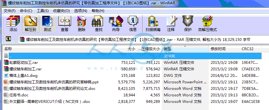
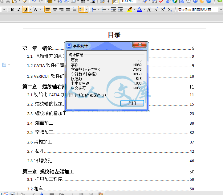
75页 14000字数+说明书+任务书+外文翻译+答辩稿+1张CAD图纸【详情如下】

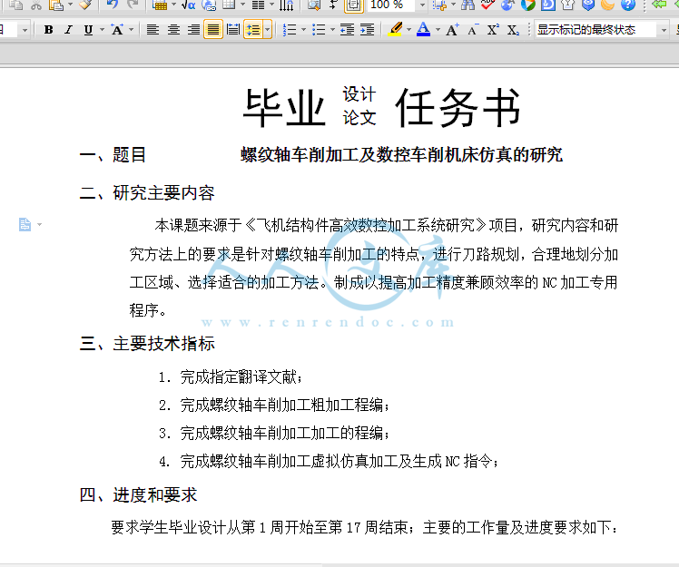
任务书.doc

外文翻译--简单的VERICUT介绍(NC文件).doc

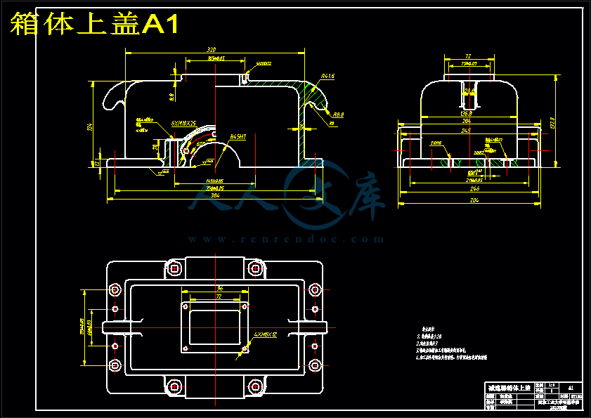
箱体上盖A1.dwg

螺纹轴车削加工.rar

螺纹轴车削加工及数控车削机床仿真的研究答辩稿.ppt

螺纹轴车削加工及数控车削机床仿真的研究论文.doc

轮廓驱动加工.rar
摘 要

  随着全球制造业竞争的日益激烈,先进制造技术的不断出现,现代数控加工技术的普遍应用,使得产品的加工周期大幅度缩短,产品的加工质量不断改善,加速了产品的更新换代,增强了产品的竞争力。因此数控加工技术的研究已成为研究重点。

在这个计算机技术发展迅速,新科技日新月异的信息社会中,制造业也发生着革命性的变化。计算机模拟、仿真技术省去了大量的工作量,大大节约了原材料成本,提高了生产效率。工厂里现在大部分机床使用的都是数控机床,数控加工出来的零件既符合外观及精度有要求,又方便操作者进行操作。掌握计算机制造技术已经是新时代我们势在必行的必须课。

  作者在查阅和搜索大量与本毕业设计相关资料的基础上,对数控加工进行研究,并在老师的耐心指导下,首先分析零件模型,根据零件的外形特点,确定加工方法。利用CATIA P3 V5R20进行数控加工程序的编制,设计出该零件的NC加工方法,并且尝试找出最合理的加工方法。从而进行零件的动态模拟数控加工。此次设计中以螺纹轴为加工对象,利用粗车,精车,切空槽,切沟槽,钻孔,钻螺纹孔等进行加工。最后,结合CATIA中设计好了的模型实例展现了VERICUT环境下数控加工仿真的全过程。

关键词:粗车,精车,CATIA,仿真,VERICUT

ABSTRACT

Since the competition of global manufacturing industry is increasingly intense, advanced manufacturing technologies appeared continuously. The general application of the modern Numerical Control Manufacturing technology, has made the processing cycle of the products shorten by a large margin, has improved the processing quality of the products, has accelerated the update of the products, and has strengthened the competitive power of the products. So the research of the process technology of numerical control has become the focal point of studying.  

The manufacturing method changes a lot with the development of the computer technology in the modern society. Computer simulation saves a lot of time for the workers and greatly saves the cost of raw materials. Also computer simulation increases production efficiency. At present, most of the factory machines are used in CNC machine tools. CNC machining parts achieved the requirement both in the appearance and in the accuracy. To master the computer manufacturing technology for the engineering working in the field of aviation is imperative.

After looking up plenty of relevant articles, author researched the process technology of Numerical Control. Under the guidance of the teacher's patience,author analysis the mold of the part at first and according to the shape characteristics of parts , assure the method of processing. Finally utilized CATIA P3 V5R20 carrying on characteristic modeling and carry on Numerical Control establishment to process procedure and designed NC processing method of the part and try to find out the most reasonable method of processing .Thus the dynamic simulation Numerical Control of carrying on the part is processed. Regarding thread spindle as the target of processing in this design . author has used Rough Turning operation, Profile Finish Turning operation, Recess Turning operation, Groove Turning operation, Drilling, Reverse Threading. Further,the whole process of NC simulation under VERICUT is shown combining with designed model instance in CATIA.

KEYWORDS: rough turning operation,profile finish turning operation,CATIA,simulation,VERICUT

目录

第一章  绪论9

1.1 课题研究的意义9

1.2 CATIA软件的简单介绍9

1.3 VERICUT软件的简单介绍10

第二章  螺纹轴右端加工11

2.1初始化CATIA加工环境11

2.2 螺纹轴的粗加工15

2.3 螺纹轴的精加工23

3.4 端面加工30

2.5 空槽加工32

2.6沟槽加工37

2.7 钻孔42

2.8钻螺纹孔46

第三章 螺纹轴左端加工50

3.1 拷贝加工程序50

3.2粗车50

3.3精车52

3.4切沟槽53

3.5 加工螺纹55

第四章 VERICUT数控仿真加工58

4.1数控加工仿真技术概述58

4.2 数控加工仿真技术的操作步骤61

4.3 数控加工的发展趋势62

4.4 VERCUT仿真加工步骤63

第五章 总结与展望74

参考文献77

致谢78

毕业设计小结79

第一章  绪论

1.1 课题研究的意义

随着科学技术的飞速发展和经济竞争的日趋激烈,产品更新的速度越来越快,多品种、中小批量生产的比重明显增加。同时,随着航空工业、汽车工业和轻工业消费品生产的高速增长,复杂形状的零件越来越多,精度要求也越来越高。此外,激烈的市场竞争要求产品研制、生产周期越来越短,传统的加工设备和制造方法已难以适应这种多样化、柔性化与复杂形状零件的高效、高质量加工要求。因此,近几十年来,世界各国十分重视发展能有效解决复杂、精密、小批量、多变零件加工的数控加工技术。在机械制造业中,大量采用以微电子技术和计算机技术为基础的数控技术,并将机械技术与现代控制技术、传感检测技、信息处理技术、网络通信技术有机地结合在一起,使其生产方式发生了革命性变化。因此研究该课题意义在于使数控技术和数控机床不断更新换代,向高速度、多功能、智能化、开放型以及高可靠性等方面迅速发发展。毕业设计小结

在这近三个月的时间里,我在导师的认真,细心的指导下,以紧张而有序的节奏顺利完成了论文工作。作者在搜索,查阅,分析有关资料的基础上,对计算机辅助制造技术有了深刻的了解,并能运用CATIA软件进行了数控加工仿真。本章下文将对作者的毕业设计做一简要小结,并讲述这个毕业设计的几点心得和体会。

1.通过作者的辛勤努力,完成了下列工作:

1).在查阅和搜索大量与本毕业设计相关的资料的基础上,在导师的耐心指导下,完成了本次毕设的螺纹轴车削加工及数控机床的仿真,也更进一步的了解了加工工艺的流程。

2).在完成加工仿真的过程中,对各种加工参数也有了进一步的认识。

2.三个月的论文工作即将结束,至此,作者谈一下在毕业设计中的几点体会:

1).为一个即将走工作岗位的大学生,在掌握本学科,本专业的知识的基础上,要了解它们最新发展趋势。只有这样,才能跟踪国内外先进的技术知识,才能在一个高起点上进行自己的研究工作。

2).保持虚心求教的精神。现代科技的飞速发展,使一个人的能力和知识面显得极为有限,特别是目前学科内容的不断拓宽,多研究领域的交叉发展,所以,只有不断向相关领域的同仁们学习,请教,才能弥补个人知识面的不足。

3).要大胆创新,勇于开拓。传统的知识方法固然成熟,可靠,但针对集体的问题它必然有其不可弥补的缺陷,此时,我们要在仔细分析其产生缺陷原因的基础上,从中大胆提出自己富有特色的办法,这往往是解决问题的关键。

3.以后的的打算

通过这次毕业设计的锻炼,对CATIA软件和数控加工技术有了新的认识,并且初步掌握了一些CATIA加工的方法,以后会在此基础上,进一步的深化学习,以达到全面掌握。有时间的话会了解一下CATIA其他的模块,为更好地工作和幸福的生活奠定基石。

参考文献

   [1] 谢龙汉等. CATIAV5数控加工[M].北京:清华大学出版社,2005年4月.

   [2] 谢龙汉等.CATIAV5机械设计[M].北京:清华大学出版社,2005年4月.

   [3] 谢龙汉等.CATIAV5机械设计应用实例[M].北京:清华大学出版社,

       2005年4月.

   [4] 谢龙汉等.CATIAV5逆向造型设计[M].北京:清华大学出版社,

       2005年4月.

   [5] 谢龙汉等.CATIAV5自由曲面造型[M].北京:清华大学出版社,

   2005年4月.

   [6]谢龙汉等.CATIAV5数控加工实例[M].北京:清华大学出版社,2005年4 月.

   [7]卜昆等.计算机辅助制造[M].北京:机械工业出版社,2006.

   [8] 计算机辅助制造.编著:王先逵.清华大学出版社.1999年1月第一版.

   [9] 计算机辅助制造.编著:罗学科.化学工业出版社.2002年11月第一版.

内容简介:
外语文献翻译外语文献翻译 翻译名称 VERICUT 翻译原文 系 别 机电工程系 专 业 机械设计制造及其自动化 班 级 姓 名 指导教师 0SessionSession 1-1- SimpleSimple VERICUTVERICUT SessionSession(NCNC 文件)文件)This session demonstrates how to execute the VERICUT program and interact with the product via standard window actions. The VERICUT software system contains demonstration files that enable users to interact with VERICUT and experience various features and options. Follow the steps in this sample session to simulate milling a block(程序段) with the standard tool path file mcdblock.mcd. NOTE: This and subsequent sessions assume VERICUT has been installed with all sample files and is accessible from any directory. Sessions also assume the Toolbar is active with all groups displayed. To verify this, select 1、ViewView ToolbarToolbar SetSet AllAll. SessionSession Steps:Steps:1.1. ExecuteExecute VERICUTVERICUTAccessAccess VERICUTVERICUT onon a a WindowsWindows computercomputerFrom the Taskbar, click StartStart ProgramsPrograms CGTechCGTech VERICUTVERICUT 5.x5.x VERICUTVERICUT 5.x5.x where 5.x is the desired VERICUT version number. With default settings, VERICUT automatically loads the vericut.usr User file from the CGTech Library- a 4-axis Mazak machine and job setup. 1 If VERICUT has been started but does not have the default User file loaded, exit VERICUT, then execute VERICUT again. This should restore the default settings required to perform this sample session. Continue with step #2 below, even if the default User file did not load as expected. However, report this fact to the instructor for future consideration. 2.2. DisplayDisplay thethe StatusStatus windowwindow toto monitormonitor thethe machiningmachining operationoperationIn the VERICUT menu bar , select InfoInfo StatusStatus 2The Status window provides information about the current tool path record being processed machining conditions. This window can be left open for constant monitoring,or use the CloseClose button to dismiss it. You can re-open and close this window at any time. 3.3. SetSet VERICUTVERICUT toto stopstop processingprocessing atat thethe endend ofof eacheach filefileIn the VERICUT menu bar, select SetupSetup MotionMotion In the Motion window, StopStop AtAt = = EndEnd ofof eacheach FileFile OKOK 4.4. CutCut thethe VERICUTVERICUT stockstock modelmodelIn the VERICUT main window, press the PlayPlay toto EndEnd icon - a milling tool path is simulated In this example, the following errors can be seen: The cut highlighted with the red ErrorError color indicates material was removed from the fixture. If left as is, this could result in a broken tool or damaged fixture. There is also some red marks where a tool holder touched the part.3The Status window ErrorsErrors field reveals that VERICUT detected 9 errors during this tool path processing. VERICUT uses high resolution graphics and color shading to provide excellent visibility of the machining process, and a high quality image of the machined part. The model in VERICUT represents how the machined part would look, if actually cut by the NC machine tool. 5.5. ReviewReview thethe errorserrors inin thethe toolpathtoolpath filefileIn the VERICUT menu bar , select AnalysisAnalysis ToolTool pathpath ReviewReview to display the Toolpath Review window. 4In the Toolpath review window, select the first error in the Error column Notice that the tool is positioned at the location where the error occurred. The cutter body removed some material while ramping in the pocket. This cutter does not cut in its center. Because the red mark is machined afterward, without the review, this error could have been missed.There is also an error where the light component collided with the Rotary Table component. This error comes from the Machine Simulation view. The machine collisions can have very dangerous repercussions. When finished reviewing the errors, select FileFile CloseClose to dismiss the Toolpath Review window. 6.6. CutCut thethe secondsecond operationoperationPress the PlayPlay toto EndEnd icon - The part is flipped and a new fixture is loaded In this example, the following errors can be seen: 5The cut highlighted with the red ErrorError color indicates material was removed from the fixture. If left as is, this could result in a broken tool or damaged fixture.The Status window ErrorsErrors field reveals that VERICUT detected 2 errors during this tool path processing. VERICUT uses high resolution graphics and color shading to provide excellent visibility of the machining process, and a high quality image of the machined part. The model in VERICUT represents how the machined part would look, if actually cut by the NC machine tool. 7.7. ReviewReview thethe errorserrors inin thethe tooltool pathpath filefileSelect AnalysisAnalysis ToolpathToolpath ReviewReview to display the Toolpath Review window and review the errors in the second toolpath. 6When finished reviewing the errors, select FileFile CloseClose to dismiss the Toolpath Review window.A Log file is automatically created by VERICUT which identifies any errors that occurred during the simulation. When errors are detected, the VERICUT Log file information identifies the exact data block which caused the error, as well as the line number of the block in the tool path file. The VERICUT Log file contains other valuable information, such as: when and what tool path file(s) were processed, simulated machining times, and more. The Log file can be viewed via the InfoInfo menumenu, as demonstrated by the next step. 8.8. ViewView thethe LogLog filefile andand searchsearch forfor errorerror messagesmessagesIn the VERICUT menu bar , select InfoInfo VERICUTVERICUT LogLog Enter the search pattern, errorerror in the text field at the top of the VERICUT Log window Select SearchSearch ForwardForward icon Error messages can be located quickly by repeatedly clicking SearchSearch ForwardForward. Sample VERICUT Log file from processing the tool path file: 7 9.9. CloseClose thethe LogLog filefile windowwindowIn the VERICUT Log window, select: FileFile ExitExit to dismiss the window. 10.10. ExitExit VERICUTVERICUTIn the VERICUT menu bar , select FileFile ExitExit (answer NoNo to the notice window-do not overwrite master sample files) 8This session provided experience with executing and interacting with VERICUT via standard user actions. The VERICUT Log file created from the tool path simulation was viewed to obtain information about the verification session, and errors detected by VERICUT. SessionSession 2-2- TypicalTypical VERICUTVERICUT SessionSession(NCNC 文件)文件)This session demonstrates how to setup VERICUT for processing a tool path file. In order to simulate the cutting action of a tool path, the following actions must be performed: 1、Define the size, shape and location of the stock to be machined2、Specify a tool path file to be processed by VERICUT and locate its origin3、Indicate how tool descriptions will be suppliedThe typical usage of VERICUT consists of opening a startup User file that contains all the 1、machine tool and 2、control configuration information. All that needs to be changed is the job specific informations like Stock, program file, and cutting tool information.SessionSession Steps:Steps: 1.1. StartStart fromfrom a a pre-definedpre-defined UserUser filefileIn the VERICUT menu bar, select FileFile OpenOpen In the upper right corner of the Open window, set ShortcutShortcut to CGTECH_SAMPLESCGTECH_SAMPLES by clicking on and selecting from the pull-down list. Select file name, mazmaz01.usr(四轴机床 B 轴)from the list of files, then OpenOpen (仿真设置:tool change)IfIf prompted,prompted, respondrespond asas follows:follows: Reset cut model? ResetReset / / Save changes? NoNo92.2. ModifyModify thethe StockStock modelmodel toto bebe a a 12.112.1 x x 5 5 x x 3 3 inchinch blockblockIn the VERICUT menu bar, select ModelModel ModelModel DefinitionDefinition: ModelModel tabtab to display the Modeling window. Set Type=BlockType=Block Length(X)=Length(X)=12.1, Width(Y)=Width(Y)=5, Height(Z)=Height(Z)=3 ApplyApply Click anywhere in the Workpiece view to make it the active view. Click on (Fit) in the VERICUT Toolbar. The block should look like the one shown below. To aid in picking the geometry in the following steps, zoom in on the angle plate/stock block area of the Machine/Cut Stock view. In the VERICUT toolbar select (Zoom to Box). In the Machine/Cut Stock view, click on a position above and to the left of the angle plate, then drag the cursor to a position below 10and to the right of the stock block forming a box around the area before releasing the mouse button. In the Modeling window, click on the PositionPosition tab, then the TranslateTranslate tab. Pick in the FromFrom field (it will highlight yellow) In the Machine/Cut Stock view, pick the middle of the back edge on the top of the stock block, as shown in the picture below. Notice that the coordinates of the selected position is automatically added to the FromFrom field. Pick in the ToTo field (it will highlight yellow) In the Machine/Cut Stock view, pick the middle of the front edge on the top of the angle plate, as shown in the picture below. 11On the Translate tab, select MoveMove. The block should be positioned on the angle plate as shown in the picture below. If your block is not positioned as shown, pick UndoUndo in the Modeling window and try again. 12 When your block is positioned correctly, pick OKOK to accept the changes and dismiss the modeling window. In the VERICUT main menu, select ViewView Orient.Orient. Select FitFit AllAll. Then Close.Close. 3.3. LoadLoad newnew programprogram filefile toto simulatesimulateIn the VERICUT main menu, select SetupSetup ToolpathToolpath. In the Toolpath window, pick the existing toolpath so that it becomes highlighted. Select ReplaceReplace. Make sure that ShortcutShortcut is set to CGTECH_SAMPLES.CGTECH_SAMPLES. Select the file named, mcd2setup.mcd, then OKOK. If you do not find mcd2setup.mcd, in the file list, make sure that FilterFilter at the bottom of the window is set to *.mcd*.mcd. 13In the Toolpath window, select OKOK, to accept the change and dismiss the window. 4.4. LocateLocate tooltool pathpath originorigin toto thethe stockstock forfor properproper cuttingcuttingIn the VERICUT main menu, select SetupSetup G-CodeG-Code Settings:TablesSettings:Tables tabtab Select and DeleteDelete all existing tables Add/ModifyAdd/Modify TableTable NameName = = ProgramProgram ZeroZero SelectSelect From/ToFrom/To LocationsLocations In the FromFrom row, NameName = = ToolTool In the ToTo row, NameName = = StockStock Select next to the Stock Move the cursor over the top of the stock workpiece- when the arrow appears in the top center of the part (see below), left-click to select this location. The value in the field should be (0 17.5 9). 14AddAdd (the table is added to the G-Code Settings window) CloseClose to dismiss the Add/Modify G-Code Table window. In the G-Code Settings window, OK,OK, to accept the change and dismiss the window. 5.5. LoadLoad a a pre-definedpre-defined tooltool librarylibrarySetupSetup ToolTool ManagerManager In the Tool Manager window, FileFile OpenOpen Shortcut=CGTECH_LIBRARYShortcut=CGTECH_LIBRARY FileFile Name=Name=vericut_demo.tls,OpenOpen FileFile CloseClose YesYes 6.6. CutCut thethe partpartIn the lower right corner of the main VERICUT window, press PlayPlay toto EndEnd 15 A User file is an ASCII text file containing the VERICUT session configuration. Saving a User file enables you to quickly re-configure the system for additional tool path processing, as well as displaying models and model images. 7 调整座标将(0 17.5 9)改为(0 17.5 10),毛坯12.112.1 x x 5 5 x x 3 3改为12.112.1 x x 5 5 x x 4 48.8. SaveSave thethe sessionsession asas typical.usrtypical.usrFileFile SaveSave AsAs Shortcut=WorkingShortcut=Working DirectoryDirectory In the File text field, enter the file name typical.usrtypical.usr SaveSave 注意:xtooltip ytooltip ztooltip 为加工坐标系9.9. ExitExit VERICUTVERICUTFileFile ExitExit This session demonstrated how to setup VERICUT for processing a tool path file. Experience was provided with supplying a tool path file name, defining a stock model, orienting a tool path and specifying how tool descriptions are to be obtained. The step prior to exiting showed how to save the VERICUT session configuration in a User file. The simulation session is repeated (and another cut model created) by executing VERICUT, opening the User file via FileFile Open,Open, then re-cutting the model.注意:1.tool tip (用户可以设定长度补偿数据);2.gage length ; subsystem1;register1;subregister1;valve8.35; subsystem1;register3;subregister1;valve8.25; subsystem1;register4;subregister1;valve 3.5; subsystem1;register5;subregister1;valve 6; subsystem1;register6;subregister1;valve 6;3.tool length compensation(用户设定长度补偿数据)(用户设定长度补偿数据应用的指令为 G43 寄存器为 H1=2001 H5=2005 等;G54 = workoffset 的用法;16SessionSession 3-3- WorkingWorking WithWith ViewsViews(clscls 文件)文件)This session shows how to define multiple views, orient views and how to navigate in the VERICUT file structure via the shortcuts. Using the ShortcutShortcut feature on file selection windows provides quick access to files in your Working Directory or CGTech library and sample files. Choosing a shortcut automatically filters for files in that directory.SessionSession Steps:Steps:1.1. OpenOpen thethe cardhold.usrcardhold.usr samplesample UserUser filefileFileFile OpenOpenShortcut=CGTECH_SAMPLESShortcut=CGTECH_SAMPLESFileFile Name=Name=cardhold.usr, OpenOpen IfIf prompted,prompted, respondrespond asas follows:follows: Reset cut model? ResetReset / / Save changes? NoNo 2.2. DefineDefine a a WorkingWorking DirectoryDirectoryFileFile WorkingWorking DirectoryDirectoryMake sure that the path is pointing to a directory where you have write permission, e.g. your home directory.Change directory if required.OKOK You can also quickly access or save files in this directory via the WorkingWorking DirectoryDirectory entry in the file selection window Shortcut list.3.3. ChangeChange viewview layoutlayoutIn the VERICUT menu bar, ViewView LayoutLayout StandardStandard 4 4 viewsviews (bottom of the pull-down list).174.4. ChangeChange viewsviews toto bebe cascadedcascaded (overlapped)(overlapped)ViewView LayoutLayout CascadeCascade5.5. ChangeChange viewsviews layoutlayout backback toto a a tiledtiled layoutlayoutViewView LayoutLayout TileTile HorizontallyHorizontally18The top of the active view is highlighted, in all other views the top is gray.6.6. ChangeChange thethe orientationorientation ofof thethe viewsviewsLeft click in VIEWVIEW 2 2 to make it the active view.ViewView OrientOrient to display the View Orient window.In the View orient window,select XYXYIncrement=Increment= 30Y-,Y-, X-,X-, FitFitLeft-click in VIEWVIEW 3 3XZXZLeft-click in VIEWVIEW 4 4ZYZYIncrement=Increment= 90, , Z+Z+FitFit AllAll 197.7. CutCut thethe workpieceworkpiecePlayPlay toto EndEnd 8.8. Re-orientRe-orient thethe cutcut workpieceworkpieceIn the View Orient window, click ZoomZoom - in View 1, Left-click top left of the boss, drag the box down and to the right, then left-click to activate the zoom.Left-click in VIEWVIEW 4 420In the VERICUT toolbar, ReverseReverse RefineRefine DisplayDisplay 9.9. DynamicallyDynamically orientorient thethe partpartDynamicDynamic Y Y RotationRotation - In the active view (View 4), left-click, then drag the cursor to the right to rotate the part as shown below. Click on DynamicDynamic Y Y RotationRotation icon again to de-activate it.10.10. CloseClose ViewView 1,31,3 & & 4 4Close views using the X icon on the top right of each viewNOTE: The above window controls appear in Windows Look & Feel. Motif and Metal Look & Feel window controls appear slightly different, but still allow you to close and minimize view windows.2111.11. AddAdd a a newnew viewviewViewView LayoutLayout AddAdd ViewView ViewView LayoutLayout StandardStandard 2 2 ViewsViews (over/under) to arrange your views as illustrated below. 12.12. OrientOrient thethe newnew viewview ( ( VIEWVIEW 1)1)Left click in the upper view (VIEWVIEW 1)1)In the View orient window, select YZYZIncrement=30Increment=30X+,X+, Y+,Y+, FitFitCloseClose 13.13. StoreStore thethe newnew viewview orientationorientationViewView Select/StoreSelect/StoreIn the Select/Store View window, highlight view 5:5: XZXZ VIEWVIEWAddAddLeft-click on the view name (VIEW 1)Rename it to FRONTFRONT ISOISO, press 22Left-click in the lower view (VIEWVIEW 2)2)In the “Select/StoreSelect/Store ViewView” window, click on XZXZ VIEWVIEWActivateActivateClick on FRONTFRONT ISOISOActivateActivateLeft-click in VIEWVIEW 1 1Click on ISO2ISO2 VIEWVIEWActivateActivateCloseClose A User file is an ASCII text file containing the VERICUT session configurations. Saving a User file enables you to quickly re-configure VERICUT for additional tool path processing, as well as displaying models and model images.14.14. SaveSave a a newnew UserUser FileFile namednamed “views.usr”“views.usr”FileFile SaveSave AsAsShortcut=WorkingShortcut=Working DirectoryDirectoryFileFile Name=Name=views.usr, SaveSave 15.15. ExitExit thethe VERICUTVERICUT sessionsessionFileFile ExitExitThis session demonstrated how to define a working directory, load a User File, and how to orient and save views in a View List. The step prior to 23exiting showed how to save the VERICUT session configuration in a user file. SessionSession 4-4- DefineDefine andand PositionPosition ParametricParametric ModelsModels(CLSCLS 文件)文件)This session demonstrates how to define and position simple parametric models to represent a job setup in a Workpiece view. In this type of verification environment, you must then achieve the desired relationship between the workpiece setup and the tool path coordinate system to simulate the cutting action. This can be done by either moving the tool path coordinate system relative to the stock model, or moving the stock model relative to the tool path coordinate system - the affect in a Workpiece view is the same. This session will demonstrate how to move the models. The step at the end of the session shows how to save the session configuration in a User file so VERICUT can be quickly and easily configured to re-process the tool path file. SessionSession Steps:Steps: 1.1. StartStart fromfrom a a newnew MillimeterMillimeter UserUser filefileFileFile Properties:Properties: GeneralGeneral tabtab DefaultDefault Units=Millimeter,Units=Millimeter, OK,OK, OKOK FileFile NewNew SessionSession (创建文件)IfIf prompted,prompted, respondrespond asas follows:follows: Reset cut model? ResetReset / / Save changes? NoNo 2.2. DisplayDisplay thethe modelmodel andand tooltool pathpath coordinatecoordinate axesaxesViewView AxesAxes Select ModelModel and CoordinateCoordinate SystemSystem CloseClose This session simulates the sample bottle.tp tool path file. The tool path requires a 100 x 200 x 50 piece of raw material with the tool path 24origin located on the top, at the center of the near side edge as shown below. The tool path origin is represented by XOrientation1, YOrientation1, ZOrientation1 axes. 为加工坐标系(程序坐标系):Xm Ym Zm 为模型坐标系;3.3. AddAdd a a StockStock modelmodel toto bebe a a 100100 x x 200200 x x 5050 mmmm blockblockModelModel ModelModel Definition:ModelDefinition:Model tabtab Type=BlockType=Block Length(X)=Length(X)=100, Width(Y)=Width(Y)=200, Height(Z)=Height(Z)=50 AddAdd 25The 100 mm dimension of the block is defined along the X direction to be consistent with the tool paths setup requirements. Similarly, the 50 mm dimension is defined along the Z direction. VERICUT initially places the block such that the entire block is positive in value. The Xm, Ym, Zm axes represent the stock model coordinate system. XOrientation1, YOrientation1, ZOrientation1 axes represent the active tool path coordinate system. The stock model must be moved to maintain the desired stock-to-tool path relationship, as shown in step 2 above. 4.4. MoveMove thethe stockstock modelmodel relativerelative toto thethe tooltool pathpath coordinatecoordinate systemsystem forfor properproper cuttingcuttingModelModel ModelModel Definition:PositionDefinition:Position tabtab Ensure Selected=ModelSelected=Model (the model axes will appear in the graphics area) TranslateTranslate tab, From=From= Select top face center of the front edge of the new block as shown below (value should be 50 0 50) 26To=To=0 0 0 MoveMove CancelCancel VERICUTVERICUT 翻译翻译第一节第一节 - - 简单的简单的 VERICUTVERICUT 介绍(介绍(NCNC 文件)文件) 本节演示了怎样执行 VERICUTVERICUT 程序以及通过标准的窗口图来表达与产品的交互作用。 VERICUTVERICUT 软件系统包含有让用户与 VERICUTVERICUT 互动以及体验各种功能和选项的演示文件。在此示例中按照以下步骤用标准的刀路轨迹文件“mcdblock.mcd”来仿真铣削毛坯。注:这个以及随后的演示都假设 VERICUTVERICUT 已经安装所有样品文件并且可以随意进入任何目录。演示还假设工具栏可用且所有分组可显示。来证实选择1、视图工具栏所有选项。27步骤:步骤:1.1. 执行执行 VERICUTVERICUT 在计算机中进入在计算机中进入 VERICUT-VERICUT-从任务栏点击开始从任务栏点击开始 程序程序 CGTechCGTech VERICUTVERICUT 5.x5.x VERICUTVERICUT 5.x5.x“5.x”是 VERICUT 的版本号。通过默认设置,VERICUTVERICUT 可以自动的装载“vericut.usr”用户文件来自 CGTech Library-一种 4 轴 MazakMazak 机床和工作设置。图 1.128 如果 VERICUT 已经启动但是没有装载默认用户文件,退出 VERICUT,然后再次启动 VERICUT。应该恢复系统默认设置来执行此示例。如果默认系统用户文件没有如期加载上,继续执行步骤 2。无论怎样,报告此事实为指导者分忧。2.2. 显示状态窗口监督加工操作显示状态窗口监督加工操作 在 VERICUT 的菜单栏中,选择 信息信息 状态状态这个状态窗口提供有关当前刀具轨迹记录正在处理加工条件的信息。此窗口可以悬空不断监测,或使用关闭关闭按钮关闭它。你可以重新开放,并随时关闭此窗口。3.3. 设置设置 VERICUTVERICUT 在每个文件的末尾停止处理在每个文件的末尾停止处理 在 VERICUT 菜单栏中,选择 设置设置 动作动作 在动作窗口中,停止段停止段=每个文件的末尾每个文件的末尾 OKOK4.4. 切入切入 VERICUTVERICUT 的库存型号的库存型号 在 VERICUT 的主窗口中,按下 播放到结尾播放到结尾 图标一种切削刀具路径模拟。29图 1.2 在这个例子中,以下错误是可见的:切口处有红色加亮 错误错误颜色表示材料从夹具取下。如果保持原样,这可能会导致刀具破损或损坏夹具。在刀柄接触零件的地方也会有红色标记。状态窗口实时错误揭示了 VERICUT 在进行此刀具路径处理时检测到的 9 处错误。VERICUT 使用高分辨率的图形和彩色底纹来提供加工过程中的优良的可视性和加工零件的高品质的图像。在 VERICUT 中的模型代表了如何加工零件看起来就像实际上是由数控机床加工一样。5.5. 在刀具路径文件中检查错误在刀具路径文件中检查错误 在 VERICUT 的主菜单中,选择 分析分析刀具路径检查刀具路径检查到刀具路径窗口的演示。30图 1.3 在刀具路径检查窗口中,选择错误列中的第一个错误。需注意,该工具定位在发生错误的位置。 当在口袋中倾斜时刀体会带出一些材料。此刀不能在其中心切。因为红色标记后加工,无需审查,可能已经错过了这个错误。这也有一个错误, “光”组件与“转盘”组件冲突。此碰撞可能会有很严重的后果。 当查看完错误时,选择 文件文件 关闭关闭来关闭该刀具路径回顾窗口。6.6. 二次切入操作二次切入操作 按下 播放至结尾 图标零件会被翻转并新的夹具夹紧。31图 1.4在此示例中,以下错误是可见的: 突出的红色错误颜色表示材料从夹具中删除。如果保持原样,这可能会导致刀具破损或损坏夹具。 状态窗口的错误表示 VERICUT 在刀具路径处理过程中检测到 2 个错误。VERICUT 使用高分辨率的图形和彩色底纹来提供加工过程中的优良的可视性和加工零件的高品质的图像。在 VERICUT 中的模型代表了如何加工零件看起来就像实际上是由数控机床加工一样。7.7. 检查刀具轨迹文件中的错误检查刀具轨迹文件中的错误选择 分析分析 刀具路径检查刀具路径检查 来显示刀具路径检查窗口并且在二次刀具路径中检查错误。32图 1.5 当完成错误检查,选择文件文件 关闭关闭来关闭刀具路径检查窗口。日志文件是由 VERICUT 在仿真过程中发生的任何错误所自动创建,当错误被检测到时,VERICUT 日志文件信息会确定所产生的错误数据块,以及该块的刀具路径文件中的行号。VERICUT 日志文件包含另外可用信息,例如:什么时候和刀具路径文件进行了处理,模拟加工时间,还有更多。日志文件可以通过菜单信息菜单信息查看,如下一步骤。8.8. 查看日志文件并搜索错误信息查看日志文件并搜索错误信息 在 VERICUT 菜单中,选择 信息信息 VERICUTVERICUT 日志日志 进入搜索方式, “错误错误”在 VERICUT 日志窗口顶部的文本字段中 选择 向前搜索向前搜索图标33错误消息可以迅速通过反复单击向前搜索定位加工刀具路径文件中的 VERICUT 日志文件:图 1.69. 关闭日志文件窗口关闭日志文件窗口 在 VERICUT 记录窗口中,选择: 文件文件 退出退出 来关闭该窗口。3410. 退出退出 VERICUTVERICUT 在 VERICUT 菜单栏中,选择 文件文件 退出退出(回答否的通知窗口不会覆盖主样本文件)本次演示提供的执行和与 VERICUT 互动的经验,是通过标准用户的操作。从刀具路径模拟创建的 VERICUT 日志文件被视为获取有关验证信息,和由 VERICUT 检测到的错误。第二节第二节 典型的典型的 VERICUTVERICUT 章节(章节(NCNC 文件)文件)本章节介绍了如何设置 VERICUT 用于加工刀具路径文件。为了模拟一个刀具路径的切断动作,下面的操作必须被执行:a) 定义毛坯的尺寸,形状和被加工位置。b) 指定一个由 VERICUT 待处理的刀具路径文件,并找到它的起源。c) 指示怎样的刀具描述会被提供。VERICUT 的典型用法包括打开一个包含所有 1 ,机床机床和 2 ,控制配置信息控制配置信息启动用户文件。所有需要改变的是工作的具体信息像毛坯毛坯,程序文件程序文件和切削刀具信息切削刀具信息。步骤:步骤:1. 从一个预先定义的用户启动文件 在 VERICUT 菜单栏,选择 文件 打开 在打开窗口的右上角,设置 快捷键 CGTECH_SAMPLES 点击并从下拉列表中选择。 从文件列表中选择文件名,mazmaz01.usr(四轴机床 B 轴) ,然后打开(仿真设置:tool change) 。35如果出现提示,答复如下如果出现提示,答复如下:复位切模式?复位复位/保存更改?否否2. 修改模型的尺寸为修改模型的尺寸为 12.1x5x312.1x5x3 英尺英尺 在 VERICUT 菜单栏,选择模型模型 模型模型定义:模型选项卡定义:模型选项卡来显示模型窗口。 设置类型类型= =块块 长(长(X X)= =12.1,宽(宽(Y Y)=5,高(高(Z Z)=3 应用应用 单击工件视图的任何地方,以使其成为活动视图。 在 VERICUT 工具栏里点击 (适合)。模块如下所示。图 2.1在下面的步骤中有助于拾取几何体,放大角板/机床的块区域/剪切视图。在 VERICUT 工具栏中选择(放大)。在机床上/剪切视图,点击上方和角板左侧的位置,然后将光标移动到下一个位置,在放鼠标按钮之前会围绕到区域框右侧。在建模窗口,点击位置位置框,然后是转化转化框。选择来自来自区(它会显示黄色) 。在机床/剪切视图,拾取模块顶部背后边缘的中间,如下图所示的画面。36请注意,所选位置的坐标被自动添加到来自来自区。图 2.2选择到区(它会显示为黄色)在机床/剪切视图,选择角板顶部的前边缘的中间,如图所示在下面的图片。37图 2.3在转化选项卡中,选择移动移动。块应该被安放在角板上,如下面图所示。如果你的块没有被定位如图所示,在建模窗口选择撤消撤消,然后重试。38图 2.4当块被正确定位,选择确定确定以接受更改并关闭模拟窗口。在 VERICUT 主菜单中,选择视图视图 向东。向东。选择适合所有适合所有。关闭。关闭。3. 加载新的程序文件来模拟加载新的程序文件来模拟在 VERICUT 主菜单中,选择设置设置 刀路。刀路。在刀路窗口中,选择现有的刀具路径,以便它会突出显示。选择替代。替代。确保确保快捷键快捷键设置为 CGTECH_SAMPLES。选择文件名,mcd2setup.mcd,然后确定确定。在文件列表中如果没有发现mcd2setup.mcd,确保在窗口底部的过滤器设置为* * . . MCDMCD。在刀路窗口中,选择确定,接受更改并关闭窗口。4. 为毛坯定位刀具路径起的起点进行加工为毛坯定位刀具路径起的起点进行加工在 VERICUT 主菜单中,选择 设置设置 G-G-代码代码 设置:表格选项卡。设置:表格选项卡。选择并删除所有现有表格。添加添加/ /修改修改表名表名= =程序零点程序零点选择从选择从/ /到位置到位置在从从列,名称名称= =刀具刀具在到到列,名称名称= =毛坯毛坯选择图标到下一个当箭头出现在零件顶部中心(见下文) ,将光标移动到超过工件的顶部,左击选择这个位置。在此出现的有效值值应为( 0 17.5 9 ) 。39图 2.5添加添加(该表被添加到 G 代码设置窗口)关闭关闭以关闭添加/修改 G 代码表窗口。在 G 代码设置窗口,确定确定 ,接受更改并关闭窗口。5. 加载一个预先定义的工具库加载一个预先定义的工具库设置设置 工具管理器工具管理器在工具管理器窗口,文件文件 打开打开快捷快捷= = CGTECH_LIBRARYCGTECH_LIBRARY文件名文件名= = vericut_demo.tls,打开打开文件文件 关闭关闭确定确定406.6.加工零件加工零件在 VERICUT 主窗口的右下角,按下播放到结尾播放到结尾图 2.6用户文件是包含 VERICUT 会话配置的 ASCII 文本文件。保存用户文件,能够快速重新配置系统进行额外的刀具路径处理,以及显示模型和模型图像。7.7.调整座标将(0 17.5 9)改为(0 17.5 10),毛坯 12.112.1 x x 5 5 x x 3 3 改为 12.112.1 x x 5 5 x x 4 48. 保存会话为保存会话为typical.usrtypical.usr文件文件 另存为另存为快捷快捷= =工作目录工作目录41在文件文本中,输入文件名 typical.usrtypical.usr保存保存注意:xtooltip ytooltip ztooltip 为加工坐标系9.退出 VERICUT文件文件 退出退出本节展示了如何设置 VERICUT 用于加工刀具路径文件。为设置刀具路径文件名提供了经验,定义毛坯模型,定向刀具路径,并说明将如何获得指定工具。在退出之前的步骤显示了在用户文件中如何保存 VERICUT 会话配置。通过执行VERICUT 仿真重复(另创切割模型),通过 文件文件 打开打开 打开用户文件,然后重新切割模型。注意:1.刀头(用户可以设定长度补偿数据);2. 标距长度;子系统 1;记录 1;子记录 1;valve8.35;子系统 1;记录 1;子记录 1;valve8.25;子系统 1;记录 3;子记录 1;valve 3.5;子系统 1;记录 4;子记录 1;valve 6;子系统 1;记录 5;子记录 1;valve 6;3. 刀具长度补偿(用户设定长度补偿数据)(用户设定长度补偿数据应用的指令为 G43 寄存器为 H1=2001 H5=2005 等;G54 = workoffset 的用法)第三节第三节 - - 工作视图(工作视图(clscls 文件)文件)42本节展示了如何定义多个视图,适合视图,以及如何通过快捷键在 VERICUT 文件结构中进行浏览。在工作目录或 CGTech 库和示例
温馨提示:
1: 本站所有资源如无特殊说明,都需要本地电脑安装OFFICE2007和PDF阅读器。图纸软件为CAD,CAXA,PROE,UG,SolidWorks等.压缩文件请下载最新的WinRAR软件解压。
2: 本站的文档不包含任何第三方提供的附件图纸等,如果需要附件,请联系上传者。文件的所有权益归上传用户所有。
3.本站RAR压缩包中若带图纸,网页内容里面会有图纸预览,若没有图纸预览就没有图纸。
4. 未经权益所有人同意不得将文件中的内容挪作商业或盈利用途。
5. 人人文库网仅提供信息存储空间,仅对用户上传内容的表现方式做保护处理,对用户上传分享的文档内容本身不做任何修改或编辑,并不能对任何下载内容负责。
6. 下载文件中如有侵权或不适当内容,请与我们联系,我们立即纠正。
7. 本站不保证下载资源的准确性、安全性和完整性, 同时也不承担用户因使用这些下载资源对自己和他人造成任何形式的伤害或损失。
提示  人人文库网所有资源均是用户自行上传分享,仅供网友学习交流,未经上传用户书面授权,请勿作他用。
关于本文
本文标题:螺纹轴车削加工及数控车削机床仿真的研究【带仿真加工程序文件】【1张CAD图纸】
链接地址:https://www.renrendoc.com/p-408839.html

官方联系方式

2:不支持迅雷下载,请使用浏览器下载   
3:不支持QQ浏览器下载,请用其他浏览器   
4:下载后的文档和图纸-无水印   
5:文档经过压缩,下载后原文更清晰   
关于我们 - 网站声明 - 网站地图 - 资源地图 - 友情链接 - 网站客服 - 联系我们

网站客服QQ:2881952447     

copyright@ 2020-2025  renrendoc.com 人人文库版权所有   联系电话:400-852-1180

备案号:蜀ICP备2022000484号-2       经营许可证: 川B2-20220663       公网安备川公网安备: 51019002004831号

本站为文档C2C交易模式,即用户上传的文档直接被用户下载,本站只是中间服务平台,本站所有文档下载所得的收益归上传人(含作者)所有。人人文库网仅提供信息存储空间,仅对用户上传内容的表现方式做保护处理,对上载内容本身不做任何修改或编辑。若文档所含内容侵犯了您的版权或隐私,请立即通知人人文库网,我们立即给予删除!