带位移电反馈的二级电液比例节流阀设计说明书.doc

带位移电反馈的二级电液比例节流阀设计【9张图纸】【优秀】

收藏

压缩包内文档预览:(预览前20页/共52页)
预览图 预览图 预览图 预览图 预览图 预览图 预览图 预览图 预览图 预览图 预览图 预览图 预览图 预览图 预览图 预览图 预览图 预览图 预览图 预览图
编号:419946    类型:共享资源    大小:2.49MB    格式:RAR    上传时间:2015-03-27 上传人:上*** IP属地:江苏
40
积分
关 键 词:
带位移 电反馈 二级电液 比例 节流阀 设计 图纸
资源描述:

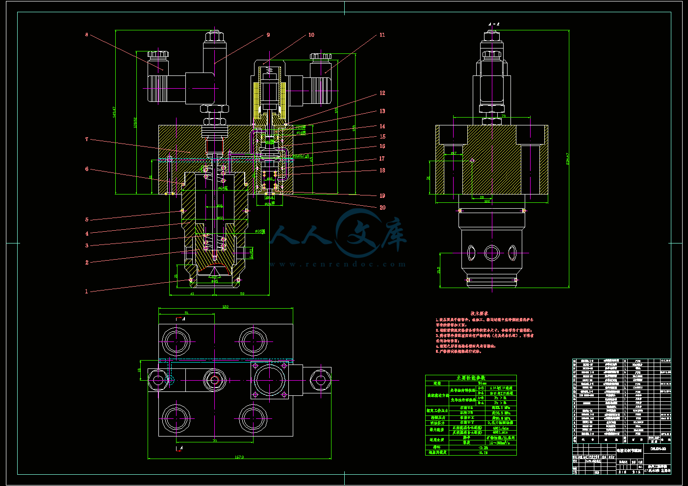
带位移电反馈的二级电液比例节流阀设计

51页 28000字数+说明书+外文翻译+9张CAD图纸【详情如下】

DBJ01-01主阀阀芯A2.dwg

DBJ01-02先导阀顶盖A3.dwg

DBJ01-03主阀阀套A2.dwg

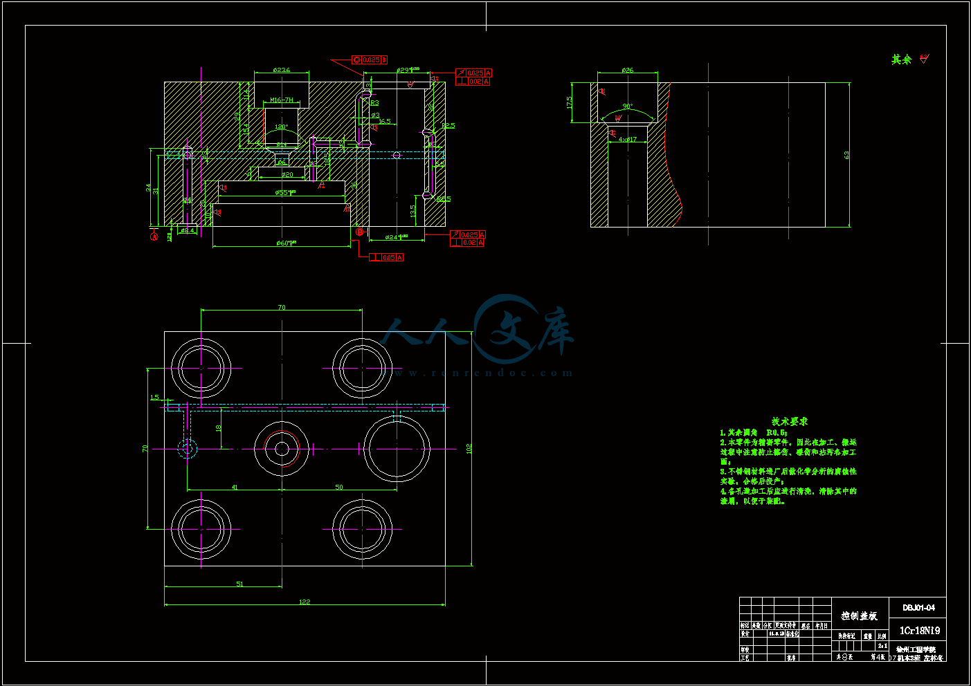
DBJ01-04控制盖板A1.dwg

DBJ01-05先导阀阀芯A2.dwg

DBJ01-06 通道块A1.dwg

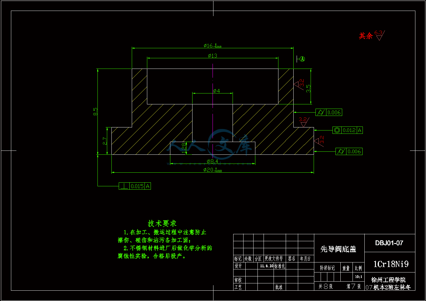
DBJ01-07先导阀底盖A3.dwg

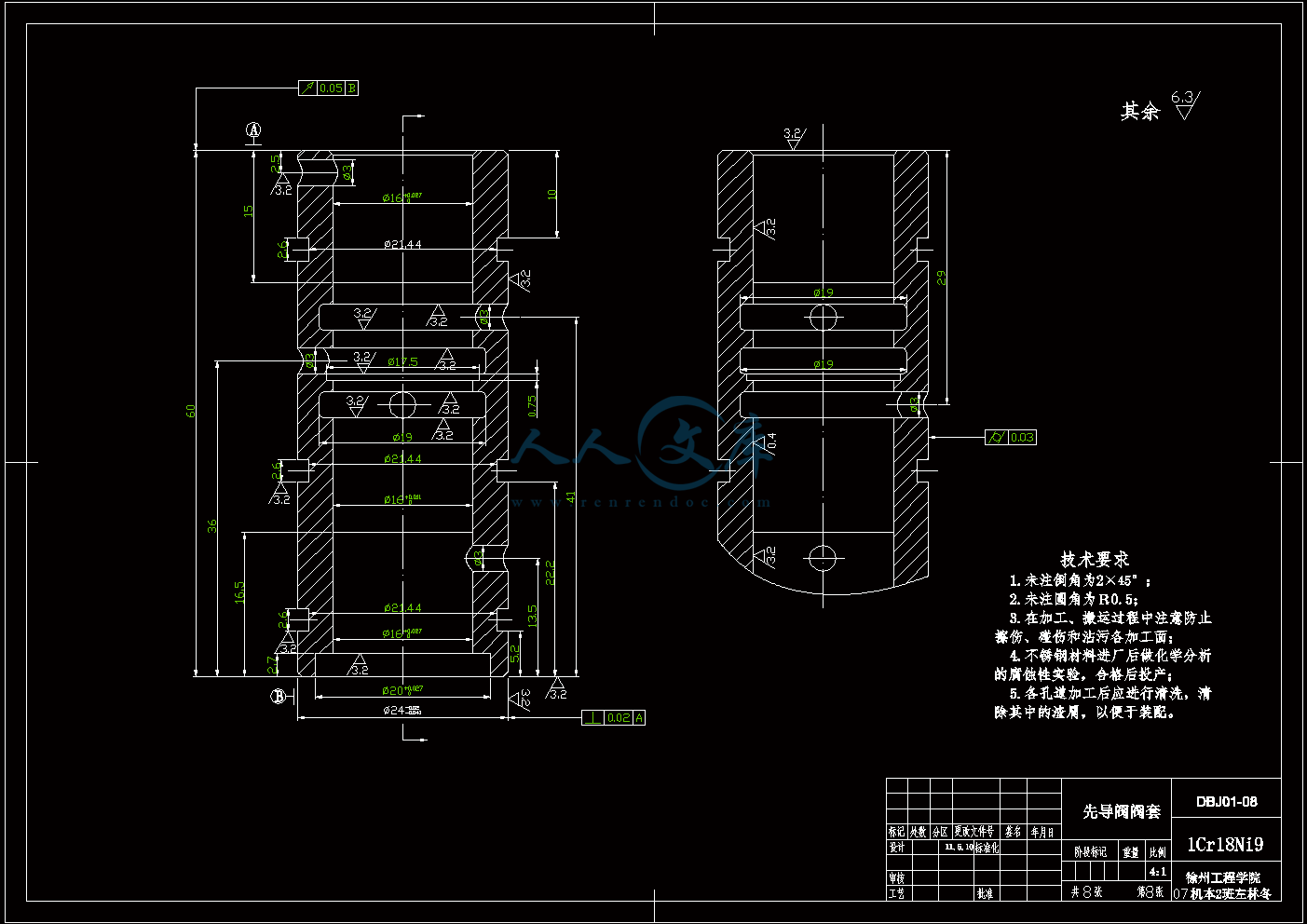
DBJ01-08先导阀阀套A2.dwg

DBJ01-00装配图A0.dwg

外文翻译--关于二级液压节流锥阀的低汽蚀研究.doc

带位移电反馈的二级电液比例节流阀设计说明书.doc

目 录

摘要I

AbstractII

1 绪论1

1.1 背景及意义1

1.1.1电液比例阀的发展阶段1

1.1.2电液比例技术在我国的发展状况1

1.1.3电液比例技术在国外发展境况2

1.2 电液比例阀的特点与分类2

1.3 设计参数4

2 流量阀控制流量的一般原理5

2.1 流量控制的基本原理5

2.2 流量阀的控制方式5

2.3 本设计中节流阀的参数5

2.4 主阀阀芯节流口形式确定6

3 比例节流阀结构设计7

3.1 插装阀介绍7

3.1.1  插装阀的组成7

3.1.2 插装阀的优点7

3.2 控制盖板的设计8

3.3 插装式主阀设计9

3.3.1 主阀阀套的设计9

3.3.2 主阀阀芯的设计11

3.3.3 插装式主阀面积比的确定12

3.3.4 主阀阀芯的受力分析13

3.4 先导阀设计17

3.4.1 减压阀的分类17

3.4.2 减压阀的工作原理18

3.4.3 先导阀阀芯详细受力分析20

3.4.4 先导阀溢流部分的设计23

3.4.5 先导阀的连接方式24

3.5 弹簧的选用24

3.5.1 主阀弹簧参数的确定24

3.5.2 先导阀弹簧参数的确定25

3.6 公差与配合的确定25

3.7 比例放大器26

3.7.1 比例放大器的分类26

3.7.2 电液比例控制元件对比例放大器的要求27

3.7.3比例放大器的基本控制电路27

3.8 比例电磁铁28

3.8.1 电- 机械转换器分类28

3.8.2 比例电磁铁29

3.8.3 比例电磁铁的分类29

3.8.4 比例电磁铁应满足的要求30

3.8.5 比例电磁铁的位移-力和电流-力特性30

3.8.6 比例电磁铁位移-力特性的实现原理31

3.9 结构设计小结31

4 节流阀工作总原理分析及其性能参数指标32

4.1原理分析32

4.2 静态性能指标33

4.3 动态性能指标34

5电液比例控制系统35

5.1 反馈的概念35

5.2 闭环控制与开环控制35

5.3 电液比例控制系统的组成36

5.4 电液比例控制系统的特点37

5.5 比例控制系统的分类37

5.6 比例控制系统的发展趋势38

5.7 小结38

6 利用UG进行运动仿真39

结论43

致谢44

参考文献45

1 绪论

1.1 背景及意义

1.1.1电液比例阀的发展阶段

比例控制技术产生于20世纪60年代末,那时的电液伺服技术已日趋完善,由于伺服阀的快速响应及较高的控制精度,以及明显的技术优势,伺服阀迅速在高精度、快速响应的领域中,如航天、航空、轧钢设备及实验设备等中取代了传统的机电控制方式。但由于电液伺服阀成本高、应用和维护条件苛刻,难以被工业界接受。在很多工业应用场合并不要求太高的控制精度或响应性,而要求发展一种廉价、节能、维护方便、适应大功率控制及具有一定控制精度的控制技术。这种需求导致了比例技术的诞生并促进了其发展。而现代电子技术和测试技术的发展为工程界提供了可靠而廉价的检测、校正技术。

1967年瑞士Beringer公司生产的KL比例复合阀标志着比例控制技术在液压系统中应用的正式开始,主要是将比例型的电- 机械转换器(比例电磁铁) 应用于工业液压阀。比例技术的发展大致可分为以下三个阶段:

   (1)从1967年瑞士Beringer公司生产Kl比例复合阀起,到70年代初日本油研公司申请了压力和流量两项比例阀专利为止,标志着比例技术的诞生时期即第一阶段。

(2) 1975年到1980年间,采用各种内反馈原理的比例元件大量问世,耐高压比例电磁铁和比例放大器在技术上也日趋成熟。可以认为比例技术的发展进入了第二阶段。

(3) 80年代,比例元件的设计原理进一步完善,采用了压力、流量、位移内反馈、动压反馈及电校正等手段,使阀的稳态精度、动态响应和稳定性都有了进一步的提高。比例技术的发展进入了第三阶段。

电液比例阀是以传统的工业用液压控制阀为基础,采用模拟式电气-机械转换装置将电信号转换为位移信号,连续地控制液压系统中工作介质的压力、方向或流量的一种液压元件。此种阀工作时,阀内电气-机械转换装置根据输入的电压信号产生相应动作,使工作阀阀芯产生位移,阀口尺寸发生改变并以此完成与输入电压成比例的压力、流量输出。阀芯位移可以以机械、液压或电的形式进行反馈。

1.1.2电液比例技术在我国的发展状况

我国电液伺服技术始于上世纪六十年代,到七十年代有了实际应用产品,目前约有年产能力2000台;电液比例技术到七十年代中期开始发展,现有几十种品种、规格的产品,约形成有年产能力5000台。但是总的来看,我国电液伺服比例技术与国际水平比有较大差距,主要表现在:缺乏主导系列产品,现有产品型号规格杂乱,品种规格不全,并缺乏足够的工业性试验研究,性能水平较低,质量不稳定,可靠性较差,以及存在二次配套件的问题等,都有碍于该项技术进一步地扩大应用。

基于以上所述,本设计将对电液比例阀中的一类——二级电液比例节流阀进行设计。该阀的功率级为二通插装阀,先导级为电液比例三通减压溢流阀。

1.1.3电液比例技术在国外发展境况

在国外,近年来比例阀出现了复合化的趋势,很大地提高了比例阀(电反馈) 的工作频宽。所以在基础阀的基础上,其他一些国家发展出了先导式电反馈比例方向阀系列,它与定差减压阀或溢流阀的压力补偿功能块进行组合,构成电反馈比例方向流量复合阀,可进一步取得与负载协调和节能效果。

随着微电子技术和数学理论的发展,国外比例阀技术已达到比较完善的程度,已形成完整的产品品种、规格系列,并对已成熟的产品进一步扩大应用,在保持原基本性能与技术指标的前提下,向着简化结构、提高可靠性、降低制造成本及“四化”(通用化、模块化、组合化、集成化)的方向发展,以实现规模经济生产,降低制造成本。

由此可见我国的电液比例技术与国际上海存在着很大的差距,我国的科技人员还要继续努力才能不被国际市场淘汰。

1.2 电液比例阀的特点与分类

比例阀把电的快速性、灵活性等优点与液压传动力量大的优点结合起来,能连续地、按比例地控制液压系统中执行元件运动的力、速度和方向,简化了系统,减少了元件的使用量,并能有效的防止在压力或速度变换时产生冲击现象。比例阀主要用在没有反馈的回路中,对有些场合,如进行位置控制或需要提高系统的性能时,电液比例阀也可作为信号转换器与放大元件组成闭环控制系统。

比例阀与开关阀相比,比例阀可以简单地对油液压力、流量和方向进行远距离的自动连续控制或程序控制,而且响应快, 工作平稳,自动化程度高,容易实现编程控制,控制精度高,能大大提高液压系统的控制水平。与伺服阀相比,电液比例阀虽然动静态性能差些,但使用元件较少,结构简单,制造比电液伺服阀容易,价格低,效率也比伺服阀高(伺服控制系统的负载压力仅为供油压力的2/3),系统的节能效果好,但使用条件、保养和维护与一般液压阀相同,可以大大地减少由污染而造成的工作故障,从而提高了液压系统的工作稳定性和可靠性。

比例控制元件的种类繁多,性能各异,有多种不同的分类方法。

(1) 按液压放大级的级数来分,又可分为直动式和先导式。直动式是由电一机械转换元件直接推动液压功率级。由于受电一机械转换元件的输出力的限制,直动式比例阀能控制的功率有限,一般控制流量都在15L/min以下。先导控制式比例阀由直动式比例阀与能输出较大功率的主阀级构成。前者称为先导阀或先导级,后者称主阀功率放大级。根据功率输出的需要,它可以是二级或三级的比例阀。二级比例阀可以控制的流量通常500L/min以下。比例插装阀可以控制的流量达1600L/min.

内容简介:
徐州工程学院毕业设计外文翻译学生姓名左林冬学院名称机电工程学院专业名称机械设计制造及其自动化指导教师陈凤腾2011年05月27日 Research on low cavitation in water hydraulic two-stage throttle poppet valve Abstract: Cavitation has important effects on the performances and lifespan of water hydraulic control valve, such as degrading efficiency, intense noise, and severe vibration. Two-stage throttle valve is a practicable configuration to mitigate cavitation, which is extensively used in water hydraulic pressure relief valves and throttle valves. The pressure distribution inside a medium chamber located between two throttles of a two-stage throttle valve is investigated through numerical simulations. The effects of the passage area ratio of the two throttles and the inlet and outlet pressures on the pressure inside the medium chamber are examined. The simulation results indicate that (a) the pressure inside the medium chamber is not constant, (b) the locations of maximum and minimum pressures inside the medium chamber are both fixed, which will not vary with the passage area ratio or the inlet and outlet pressures, and (c) the ratio of the pressure drop across the front throttle to the total pressure drop across the two-stage throttle valve is nearly constant. The critical cavitation index of the two-stage throttle valve is then established. A semiempirical design criterion is obtained for the water hydraulic two-stage throttle valve. The correlation between the critical cavitation index and the passage area ratio of the two throttles is investigated. Relevant validation experiments are conducted at a custom-manufactured testing apparatus. The experimental results are consistent with the simulated ones. Further analyses indicate that (a) the large backpressure can improve not only the anti-cavitation capability but also the total load rigidity of the water hydraulic two-stage throttle valve, (b) an appropriate passage area ratio will be beneficial for improving the anti-cavitation capability of the water hydraulic two-stage throttle valve, and (c) the water hydraulic two-stage throttle valve with a passage area ratio of 0.6 would have the best anti-cavitation performance with the lowest risk of cavitation. Keywords: computational fluid dynamics simulation cavitation load rigidity passage area ratio two-stage throttle valve water hydraulics 1 INTRODUCTION Water hydraulic systems are operated with raw water (pure tap water) substituting for mineral oil. They have advantages in terms of durability, reliability, safety, and cleanness. Such systems are becoming more and more popular, especially in fields of steel and glass production, coal and gold mining, food and medicine processing, nuclear power generation, ocean exploration, and underwater robotics 15. Because the opening of a water hydraulic control valve is very small compared with that of oil valve, the water flow velocity through the water hydraulic control valve is larger under the same pressure condition; thus cavitation erosion may occur due to the high vapour pressure of water. Cavitation has an important effect on the performance and lifespan of water hydraulic control valve, such as degrading efficiency, intense noise, and severe vibration. Previously, a number of studies on the relationships between cavitation and discharge coefficient, thrust force and pressure distributions in the valves, and mitigation of cavitation damage were carried out through increasing outlet pressure of valves, modifying shapes of throttles, adding stages of valves, selecting anti-corrosion materials for parts, and controlling maximum fluid temperature and flow velocity. Tsukiji et al. 6 investigated cavitation by flow visualization in hydraulic poppet-type holding valves to reduce cavitation. Some measures were employed to diminish noise and cavitation through controlling flowrate, upstream pressure, downstream pressure, and valve lift in case of converging flow. Aoyama et al. 7 studied experimentally the unsteady cavitation performance in an oil hydraulic poppet valve. It was found that, as absolute values of the variation rates of inlet and outlet pressure increased, the incipient cavitation index exhibited a tendency to decrease, whereas the final cavitation index a tendency to increase under all geometrical parameters. As the absolute values of the variation rates of inlet and outlet pressure further increased, the hysteresis between the incipient and final cavitation indices would become larger than ever for each combination of the valve and valve seat. Ishihara et al. 8 studied oil flow unsteadiness effect on cavitation phenomena at sharp-edged orifices. The rate of pressure drop across the orifice was kept constant, and cavitation incipience and finale were recorded by using scattered laser beams showing that (a) there existed two types of cavitation, namely, gaseous cavitation and vapourous cavitation, and (b) cavitation incipience and finale varied with the initial condition, the temperature of hydraulic oil, and the rate of pressure drop. Johnston et al. 9 carried out an experimental investigation of flow and force characteristics of hydraulic poppet and disc valves using water as the working fluid. The axisymmetric valve housing was constructed from clear perspex to facilitate flow visualization; tests were performed on a range of different poppet and disc valves operating under steady and non-cavitating conditions, for Reynolds numbers greater than 2500. Measured flow coefficients and force characteristics showed obvious differences depending on valve geometry and opening. Vaughan et al. 10 conducted computational fluid dynamics (CFD) analysis on flow through poppet valves. Simulations were compared with experimental measurements and visualized flow patterns. A qualitative agreement between simulated and visualized flow patterns was identified. However, errors in the prediction of jet separation and reattachment resulted in quantitative inaccuracies. These errors were due to the limitations of the upwind differencing scheme employed and the representation of turbulence by the k 1 model, which was known to be inaccurate when applied to recirculating flow. Ueno et al. 11 investigated experimentally and numerically the oil flow in a pressure control valve under an assumption of non-cavitating conditions for various configurations of the valves on the basics of a finite difference method. They concluded that the main noise of the testing valves was generated from cavitation, and the noise was affected by the valve configuration. Pressure measurements and flow visualization at two locations in a valve chamber were also performed on the basis of two-dimensional models. Through comparisons of the measured and calculated results, several design criteria were set up for low-noise valves. Martin et al. 12 investigated cavitation in spool valves in order to identify damage mechanisms of the related components. Tests were conducted in a representative metal spool valve as well as a model being three times larger. Data taken under non-cavitating conditions with both of these valves showed that the orientation of high-velocity angular jets would be shifted due to variations in valve opening and Reynolds number. By means of high-frequency response pressure transducers strategically placed in the valve chamber, the cavitation could be sensed through the correlation of noise with a cavitation index. The onset of cavitation could be detected by comparing energy spectra for a fixed valve opening with a constant discharge. The incipient cavitation index, as defined in this investigation, was correlated with the Reynolds number for both valves. Gao et al. 13 performed a simulation of cavitating flows in hydraulic poppet valves by means of an renormalization group (RNG) k 1 turbulence model, which was derived from the nstantaneous NavierStokes equations based on the RNG theory. Experiments were conducted to catch cavitation images around the seat of a poppet valve from perpendicular directions, using a pair of industrial fibre scopes and a high-speed visualization system. The binary cavitating flowfield distributions obtained through digital processing of the original cavitation image showed satisfactory agreement with numerical results; the vibrations of valve body and poppet induced by the cavitating flow were detected using a vortex displacement transducer, a laser displacement metre and a digital strain device. It was concluded that the opening and cone of a conical valve had significant effects on the intensity of cavitation. However, in this study, only downstream cavitation inception volume was analysed in estimating the anti-cavitation capability, whereas the effects of outlet pressure were not considered. Oshima et al. 14 experimentally investigated the influences of (a) chamfer length in the valve seat, (b) the poppet angle, and (c) the oil temperature on the flow characteristics and the cavitation phenomena, using water instead of oil as the working medium in water poppet throttles. The cavitation phenomena were directly observed and the pressure distribution between the valve seat and poppet surface was measured in water poppet throttles. Comparison analyses on the condition of critical cavitation were conducted between oil and water. It was found that the discharge coefficient and the critical cavitation number for water poppet throttles were considerably different from those of oil ones, due to the high density and low viscosity of water. Recently, Liu et al. 15, 16 investigated experimentally the flow and cavitation characteristics of a two-stage throttle in water hydraulic system; they concluded that the two-stage throttle had stronger anti-cavitation capability than the single-stage one, and that the shape of seats also affected the anti-cavitation capability of the throttles. The cavitation choking appeared only when cavitation index was less than 0.4. They also conducted several studies on the relationships between the cavitation and the configuration of control valve, and between the cavitation and the passage area ratio of two throttles. However, the pressure between two throttles was assumed to be constant, which may not be applicable for the two-stage throttle with a medium chamber. As an extension of Liu et al. 15, 16, this research will focus on the investigation of cavitation characteristics in the water hydraulic two-stage throttle poppet valve. This objective entails the following research tasks: (a) on the basis of the RNG k 1 turbulent model, numerical simulations will be conducted to investigate the pressure distribution inside the medium chamber located between the two throttles, (b) the effect of the passage area ratio of the two throttles and pressure between the two throttles on the anti-cavitation capability will be studied, (c) the design criteria of the two-stage throttle valve will be established for low-cavitation and noise, and (d) experimental validation will be performed through a custom-manufactured testing apparatus, to demonstrate applicability of the developed simulation approach and design criteria. 2 SIMULATION OF PRESSURE BETWEEN TWO THROTTLES 2.1 Statement of problems If water pressure decreases below the saturation vapour pressure pv (absolute pressure) of water under a given temperature, the vapour or gas will spill out of the water, and then cavitation will occur. For water, pv . 0.023 MPa when the temperature is 20 8C. Generally, the likelihood of the cavitation for the throttle valve can be measured by a cavitation index (K ), which can be expressed as follows The critical cavitation index (Kc) is the minimum cavitation index for the throttle under non-cavitating flow in throttle valve. For a single-stage throttle valve, Ksc . 0.4 14, 1720. It denotes that, if the cavitation index K is less than 0.4, the cavitation will occur. Therefore, the cavitation index (K ) should be larger than 0.4 so as to avoid cavitation in the throttle valve. The larger the pressure drop across the throttle valve, the smaller the cavitation index (and thus greater probability of cavitation for the throttle valve). The two-stage throttle valve is a practicable configuration to mitigate cavitation, being extensively used in water hydraulic pressure relief valves and throttle valves. Figure 1(a) is a scheme of water hydraulic two-stage throttle valve, which consists of a poppet and a seat with a step shape bore. There are two tandem throttles to take the total pressure drop (pin -pout). Therefore, the pressure drop across each stage throttle is less than the total drop of the valve, which is differed from a single-stage throttle. Hence, the cavitation index of each stage throttle should be larger than that of the single-stage throttle valve, leading to a reduced possibility of cavitation and erosion. For the two-stage throttle valve, the definition of cavitation index Kt can be analogously expressed as follows Actually, for each stage throttle, the critical conditions for avoiding cavitation in a single-stage throttle should be satisfied. Then The pressure distribution inside the medium chamber located between the two throttles should be obtained to calculate cavitation indices for both stages. CFD simulation will be undertaken to explore the pressure distribution of the medium chamber. 2.2 Mathematical model In view of the axisymmetric structure of the two-stage throttle valve, the computational domain is simplified to a two-dimensional axisymmetric geometrical model (ABCDE), as shown in Fig. 1(a); its grids are generated (Fig. 1(b) through an advanced grid preprocessor (Gambit of software package FLUENT) 21, 22. In Fig. 1(a), AB and BC denote fixed wall of seat, ED is fixed wall of poppet, CD the inlet, and AE the outlet. The water is assumed to be incompressible viscous fluid with = 998.2 kg/m3, and =1.00710-6m2/s; the effects of pressure and temperature on the density and viscidity of water are neglectable; all of the walls are assumed adiabatic with a zero slip velocity. The inlet and outlet boundaries can be specified as pressure levels. The RNG k 1 equation model (turbulence kinetic energy equation k and dissipation equation 1) and the multiphase model are used in this research. The Boussinesq hypothesis is employed to relate Reynolds stresses to the mean velocity gradients The turbulence kinetic energy (k) and its rate of dissipation (1) are obtained from transport equations (6) and (7), respectively In this research, the multiphase model involves liquid and gas phases that are considered as interpenetrating continua. The law of conservation of mass and momentum is satisfied in each phase. The derivation of the conservation equations can be done by ensembling the local instantaneous balances for all of the phases. Volume fractions (ap) represent the space occupied by gas phase. The continuity equation for gas phase can yield In these equations, Gk represents the generation of turbulence kinetic energy due to the mean velocity gradient; sk and s1 are the inverse effective turbulent Prandtl numbers for k and 1, respectively.2.3 Simulation results Sensitivity analyses of the variations of pressures inside the medium chamber along with the changing passage area ratio of the two throttles and the inlet and outlet pressures were performed. As a large number of numerical simulations were conducted, it is impossible to include all of the results here. Instead, representative outcomes are explicated to demonstrate important findings. The simulated contours of the volume fraction of water vapour are shown in Fig. 2. The passage area ratio (r) could significantly affect the cavitation occurrence and intensity under conditions of pin . 10 MPa and pout . 1 MPa. There are several key transferring points for passage area ratio including r . 0.2, 0.5, and 2.0. When r was less than 0.2, water vapour would be formed inside the medium chamber of the two-stage throttle valve, and the corresponding maximum volume fraction of water vapour would increase up to 85.3 per cent as shown in Fig. 2(a). This was ascribed to the high fluid velocity and the intense recirculation inside the medium chamber. The recirculation would cause the formation of a low-pressure zone and thus potential cavitation. With an increasing r level, the volume fraction of water vapour would be reduced. When r ranged from 0.5 to 0.8, the maximum volume fraction of water vapour would fall (to 0.162 per cent or below) and, consequently, the possibility of cavitation would decrease. However, with further increase of the passage area ratio (e.g. when r . 2.0), the maximum volume fraction of water vapour would increase up to 5.1526.7 per cent as shown in Figs 2(c) and (d); thus, cavitation would occur again. The simulated contours of pressure inside the medium chambers are presented in Fig. 3 when the passage area ratio varied from 0.1 to 6.0 under conditions of pin . 10 MPa and pout . 1 MPa. It can be seen from Fig. 3 that, when r was less than 0.2 or larger than 2.0, the pressure drop would be solely taken by the front or rear throttle of the two-stage throttle valve. This looked like a single-stage throttle valve, with its anti-cavitation capability being similar to that of single-stage throttle valve. When r was between 0.2 and 2.0, the total pressure drop would be shared by the two tandem throttles. Obviously, a sound r level would help suppress cavitation inception in the water hydraulic two-stage throttle poppet valve. In order to clarify the correlations among pressure levels inside the medium chamber and the related impact factors (r, pin, and pout), a virtual line (l ) was employed to locate the pressure levels inside the medium chamber. They ranged from the midpoint of line AE to the midpoint of line CD. The virtual line was divided into eight parts, and the corresponding nodes were marked by ordinal numbers (from 0 to 8); the pressure levels on the virtual line were denoted as pl. The effects of the passage area ratio (r) on the pressure (pl) under condition of pin . 10 MPa and pout . 4 MPa are illustrated in Fig. 4. The pressure level would vary with the passage area ratio. The larger the passage area ratio r, the higher the pressure level on the virtual line. However, when r is less than 0.2, the pressures inside the medium chamber would become low. This was attributed to the small front throttle, which could be considered as a jet nozzle. The fluid would have less direction variations and jet contraction when passing through the front throttle. A high flow velocity through the front throttle would be generated, and thus the pressure would decrease rapidly. In such a case, the flow pattern would be like that of a single-stage throttle. From Fig. 4, the pressure levels on the virtual line (l) would vary at different space positions, confirming that the pressure levels inside the medium chamber were not constants. It was also very interesting that the locations of the maximum and minimum pressures were fixed on the virtual line, being indifferent of the variations of the passage area ratio. 关于二级液压节流锥阀的低汽蚀研究 摘要:汽蚀对于液压控制阀的性能和寿命有重要影响,如引起效率的降低,产生强烈的噪音和振动。二级节流阀目前作为一种来减小汽蚀的装置被广泛用于液压安全阀和节流阀。可以通过数值模拟的方法来研究介质在二级节流阀介质腔的压力分布。对两个节流阀的截面比和介质腔内的进出口压力产生的影响进行研究。仿真结果表明,(1)介质腔内的压力不是固定的,(b)介质腔最大和最小压力的位置都是固定的,不会随着通道面积比率或进出口压力而变化,(c)流过前面节流阀和流过二级节流阀的总压降的压降比值几乎不变。然后建立二级节流阀临界汽蚀指标,。通过该二级液压节流阀得到设计的经验准则。对临界汽蚀指标和通道的两个截面比例之间的关联性进行实验研究。相关验证实验在一个定制的测试仪器中进行。 实验结果和模拟研究是一致的。进一步的分析表明,(a)大的反压力不仅可以提高抗汽蚀能力还可以改善二级液压节流阀的总负荷刚性、(b)一个适当的通道面积比例有利于提高二级液压节流阀的抗汽蚀能力(c)通道面积比例为0.6的二级液压节流阀会有最好的抗汽蚀能力,而且产生汽蚀的风险最低。关键词:流体动力学仿真计算、汽蚀、负载刚度、通道面积比率、二级节流阀。1介绍 水压操作系统用原水(纯自来水)替代矿物油。就他们优势而言,有耐久性、可靠性、安全性、以及清洁。这种系统特别是在钢和玻璃生产、煤炭和金矿开采、食品和医药加工、核电、海洋勘查、水下机器人等领域正变得越来越流行。和油阀相比水压控制阀门开口是非常小的,所以在相同的压力条件下通过水压控制阀门的水流速会更大,但是由于具有较高压力的蒸汽水的存在,就可能出现汽蚀。汽蚀对水液压控制阀的性能和寿命有重要影响,如降低效率、强烈的噪声以及严重的振动。之前,有许多关于汽蚀现象、流量系数、驱动力和压力在阀门分布、通过增加阀门出口压力减小汽蚀、修改节流形状、提高阀门零件材料的耐腐蚀级别、以及控制最大流体温度、流速峰值的研究。6研究利用提升型保持阀的可视化流体来减少汽蚀。通过控制流量、上下游压力和阀门开启的集聚流动等一些措施来减小噪音和汽蚀。 Aoyama7实验研究了在油压提升阀中出现的不稳定汽蚀现象,结果发现,随着入口和出口压力变化速率绝对值的增加,初期的汽蚀指数表现出一种减小的倾向,而最后的汽蚀指数有增加到所有的几何参数之下的趋势,。随着入口和出口压力变化速率的绝对值进一步增大,滞环之间初期和最终的汽蚀指数会比以往任何时候每个组合阀门和阀座的都大。 Ishihara8研究了不稳定的油液流动对小孔通道的汽蚀现象影响。使通过孔口的压降速度保持不变,利用分散雷射光束记录的最初和最终汽蚀表现出(a)存在着两种类型的汽蚀,即气态的汽蚀和类蒸汽汽蚀现象(b)初期和最终汽蚀随着初始条件,液压油的温度,以及压降的速率变得多样化。 Johnston9进行了一项关于在提升和圆盘液压阀中流动和力学特性的实验研究,并采用水作为工作介质。制造出具有轴对称性的有机玻璃阀门外壳,便于促进可视化流动,实验研究了在稳定且没有汽蚀雷诺数大于2500的条件下一系列不同的对提升和圆盘阀的操作。测量显示的流量系数和力学特性随着阀门几何形状和开口有着明显的不同。 Vaughan10对流过提升阀的油液进行了流体动力学计算(CFD)分析。仿真被用于比较实验测量和可视化流动模式。一种关于模拟和可视化的流动模式的可行性被认同。然而,在预测射流分离和复位时的错误导致了定量的不精确性。这些错误是由于本身的局限性造成的,可以采用迎风差分方案表示k - 1湍流模型,但该模型用于循环流量时是不准确的。 Ueno 11用实验和数值模拟的方法研究了用最基本的有限差分在假设没有汽蚀在条件下对不同构造压力控制阀的油液流动,。他们总结说,测试阀的主要噪声是由汽蚀造成的,同时噪声也受阀门结构的影响。对阀腔两个位置的压力测量和可视化流动在二维模型的基础上进行研究。通过测量和计算结果的比较,可以建立低噪声阀门设计的几个准则。 Martin12通过研究芯阀的汽蚀现象问题用来识别和损伤机制相关的组件。在典型的金属芯阀和一个三倍大的模型中进行测试。两种液压阀在没有汽蚀条件下得到的数据表明,由于阀门开启度和雷诺数的影响,阀的高喷流方向的角度会发生变化。通过放置在阀室的高频压力响应传感器,可以利用噪声和汽蚀指数之间的相关联系来检测汽蚀。汽蚀可能通过对一个不变排放量的固定开启度阀门进行能量谱比较来检测。在这次调查中所定义的初期汽蚀指数是与两个阀门雷诺数有关的。 Gao 13通过基于RNG n - s方程理论中派生出来的重整化群(RNG紊流模型),对液压提升阀中的汽蚀流动进行了模拟。试验研究用一对工业纤维和一个高速可视化系统从垂直方向捕捉提升阀座周围的汽蚀图像。通过数字处理原汽蚀图像所获得的汽蚀二进制分布流场与数值结果达到令人满意的一致性;由汽蚀流动引起的阀体和提升阀的振动可以利用被称作激光测距应变装置的涡流位移传感器进行测量。实验表明锥阀的开口和锥度对汽蚀的强度有非常重要的影响。然而在此研究中,计算抗汽蚀能力时只分析了大量下游的初期汽蚀,出口压力的影响则未被考虑。 Oshima14通过试验研究了(a)阀座的槽长度和(b)提升阀角度,和(c)油温对流动特性和汽蚀现象的影响,并在液压提升阀用水代替油作为工作介质。汽蚀现象可以被直接观察到而且也对水压提升阀中阀座和提升阀表面压力分布进行了检测分析。在临界汽蚀的条件下对油和水进行比较分析。实验发现水压提升阀的流量系数和临界汽蚀数据不同于油压的,因为水具有较高的密度和较低的粘度。最近,Liu15、16进行了液压系统中二级液压阀的流动、汽蚀特性的试验研究;他们得出的结论是
温馨提示:
1: 本站所有资源如无特殊说明,都需要本地电脑安装OFFICE2007和PDF阅读器。图纸软件为CAD,CAXA,PROE,UG,SolidWorks等.压缩文件请下载最新的WinRAR软件解压。
2: 本站的文档不包含任何第三方提供的附件图纸等,如果需要附件,请联系上传者。文件的所有权益归上传用户所有。
3.本站RAR压缩包中若带图纸,网页内容里面会有图纸预览,若没有图纸预览就没有图纸。
4. 未经权益所有人同意不得将文件中的内容挪作商业或盈利用途。
5. 人人文库网仅提供信息存储空间,仅对用户上传内容的表现方式做保护处理,对用户上传分享的文档内容本身不做任何修改或编辑,并不能对任何下载内容负责。
6. 下载文件中如有侵权或不适当内容,请与我们联系,我们立即纠正。
7. 本站不保证下载资源的准确性、安全性和完整性, 同时也不承担用户因使用这些下载资源对自己和他人造成任何形式的伤害或损失。
提示  人人文库网所有资源均是用户自行上传分享,仅供网友学习交流,未经上传用户书面授权,请勿作他用。
关于本文
本文标题:带位移电反馈的二级电液比例节流阀设计【9张图纸】【优秀】
链接地址:https://www.renrendoc.com/p-419946.html

官方联系方式

2:不支持迅雷下载,请使用浏览器下载   
3:不支持QQ浏览器下载,请用其他浏览器   
4:下载后的文档和图纸-无水印   
5:文档经过压缩,下载后原文更清晰   
关于我们 - 网站声明 - 网站地图 - 资源地图 - 友情链接 - 网站客服 - 联系我们

网站客服QQ:2881952447     

copyright@ 2020-2025  renrendoc.com 人人文库版权所有   联系电话:400-852-1180

备案号:蜀ICP备2022000484号-2       经营许可证: 川B2-20220663       公网安备川公网安备: 51019002004831号

本站为文档C2C交易模式,即用户上传的文档直接被用户下载,本站只是中间服务平台,本站所有文档下载所得的收益归上传人(含作者)所有。人人文库网仅提供信息存储空间,仅对用户上传内容的表现方式做保护处理,对上载内容本身不做任何修改或编辑。若文档所含内容侵犯了您的版权或隐私,请立即通知人人文库网,我们立即给予删除!