高楼火灾逃生器设计说明书.doc

高楼火灾逃生器设计【8张图纸】【优秀】

收藏

压缩包内文档预览:(预览前20页/共37页)
预览图 预览图 预览图 预览图 预览图 预览图 预览图 预览图 预览图 预览图 预览图 预览图 预览图 预览图 预览图 预览图 预览图 预览图 预览图 预览图
编号:421966    类型:共享资源    大小:1.83MB    格式:RAR    上传时间:2015-03-31 上传人:上*** IP属地:江苏
39
积分
关 键 词:
高楼 火灾 逃生器 设计 图纸 火灾逃生器
资源描述:

高楼火灾逃生器设计

36页 14000字数+说明书+外文翻译+8张CAD图纸【详情如下】

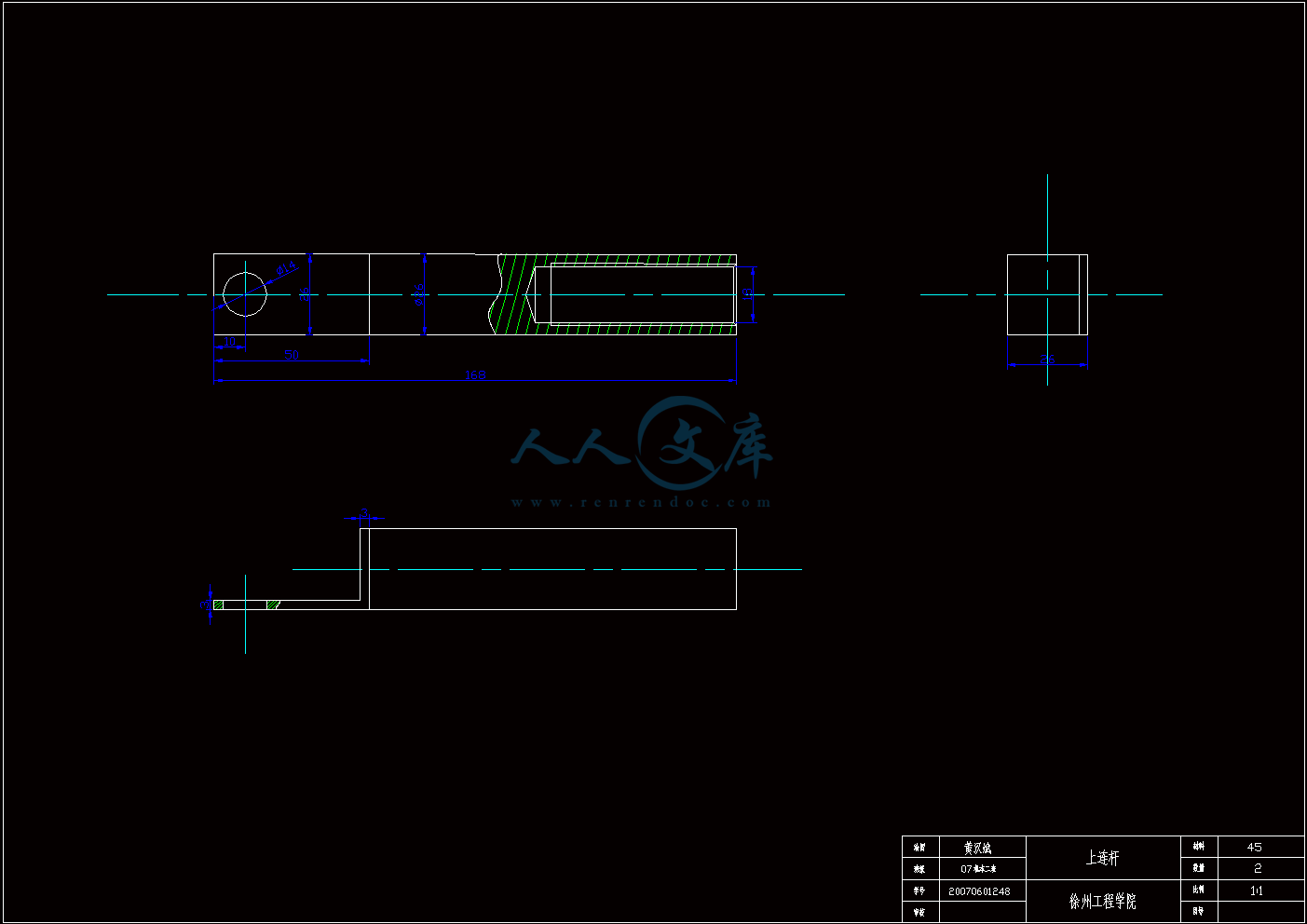
上连杆.dwg

中连杆.dwg

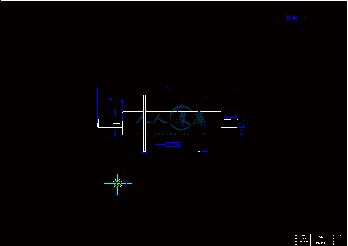
主动轴.dwg

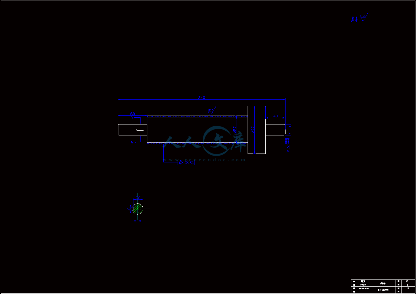
从动轴.dwg

外文翻译--以知识为基础的方法在机械产品设计任务中的实施.doc

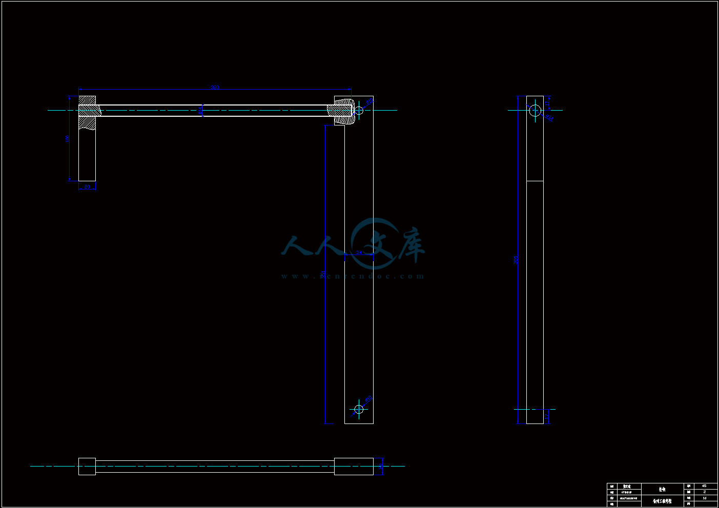
挂钩.dwg

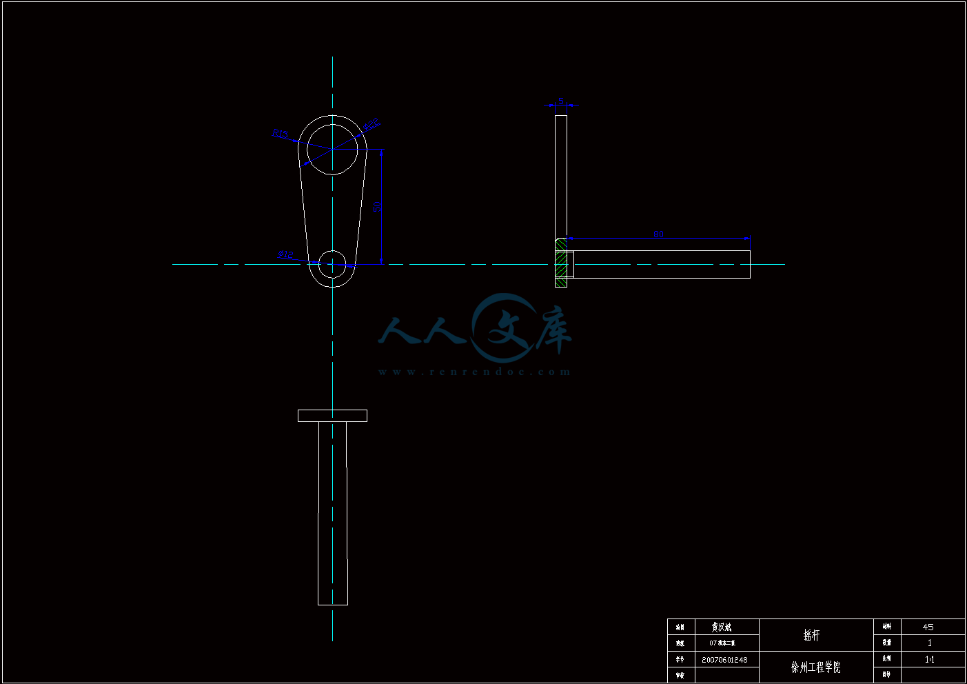
摇杆.dwg

板件.dwg

装配图.dwg

说明书.doc

高楼火灾逃生器设计说明书.doc

目       录

摘要II

AbstractIII

1 绪论1

1.1 设计背景及意义1

1.2 国内外研究概况2

1.3 高楼火灾逃生器的实例3

1.3.1 内凸轮式高楼火灾逃生器3

1.3.2 涡轮蜗杆式高楼火灾逃生器4

1.3.3 钢丝绳防滑逃生装置4

1.3.4 心摩擦式高楼火灾安全逃生器5

2 整体方案设计6

2.1 方案构设6

2.1.1 方案一6

2.1.2 方案二9

2.1.3 方案三11

2.2 方案的比较与选择12

3 装置零部件设计13

3.1 轴的设计13

3.1.1 轴的概述13

3.1.2 主动轴的设计14

3.1.3 从动轴的设计15

3.2 齿轮的设计16

3.2.1 齿轮的概述16

3.2.2 齿面接触疲劳强度和齿根弯曲强度设计16

3.3 棘轮的设计20

3.3.1 棘轮的概述20

3.3.2 棘轮的设计21

3.4 其他零部件的设计选择22

3.4.1 标准件的选择22

3.4.2 安全座椅的选择23

3.4.3 挂钩的设计24

4 计算和验证24

4.1 静力学平衡计算25

4.2 绕绳的计算26

4.3 速度计算26

结论29

致谢30

参考文献31

摘要

   本文从开始介绍了高楼逃生装置的背景和研究意义,并对现有的一些高楼逃生装置进行了分析和对比,发现大多数的装置有成本高、机构复杂、安全系数低等一些不足之处。本设计根据机械创新理论,设计出一种基于负反馈闭环系统的高楼逃生装置,该装置具有成本低、操作简单、安全系数高、纯机械无电气结构等优点,最后通过对设计机构的零部件进行计算,得出整个机构的图形,在多次试验和计算之后,确定了不论是小孩还是老人都能从高楼平安降落到地面,达到了本次设计的目的。

关键词 高楼火灾逃生器;机械创新理论;往复;可控

1 绪论

1.1 设计背景及意义

随着建筑高度的增加和日趋密集,建筑的安全隐患也越来越多,即使在发达国家的高楼遇有火灾、爆炸等事件时,由于时间、空间等诸多因素的限制,人员自救逃生也是一个急待解决的重要问题。高楼火灾的有效救援和应急逃生,已经成为人们高度关注的社会问题。高层建筑一般功能较多,内部通道和外部环境情况复杂,一旦发生火灾,由于烟囱效应,火势和浓烟就会迅速扩大,很短时间内蔓延到内部楼梯和走廊,封锁正常的疏散通道,至使楼上被困人员无法逃生。所以逃生人员自救是一个亟待解决的重要问题。高楼突然失火或其他灾难发生时 ,电梯不能用,楼梯阻塞,而一般地面救援装备的举高和投射能力又远远的落后于高层建筑的高度发展而且装备体积庞大受道路交通,建筑周边环境等方面的影响因而延误救援时机,这样的情况每年都有发生 ,也有很多人因无法逃生而遇难,所以怎样快速有效的逃离火灾建筑成了决定生死的问题,而高楼逃生装置在这样的环境下应运而生。然而在人们将越来越多的精力和时间都投入到对安全问题保障研究的同时,却忽略了最基础的一种手段 ,在人们越来越多的用到各种高科技和现代手法进行安全保障的同时,却忽略意外事件的发生,是不可以借助外力和各种现代手段解决的 ,要靠最基础和最简单的方式 ,也就是机械传动的方式才是最安全和稳定的。

本课题要求针对高层建筑实际情况,设计一种在发生火灾情况下,能帮助人方便、快捷的逃生的工具。要求设计出的逃生器能适合各种结构的建筑物,运行实现自动化,并且要求操作方便,可以折叠,体积和重量在一个人可以操作的限度范围内。可以多次往返高层建筑进行营救。从而能最大限度的减少火灾中的人员伤亡。通过分析比较现有的一些高楼逃生器,大多数装置虽然能达到高楼逃生这一功能,但其结构原理复杂,操作繁琐,安全性差,生产成本高,部分装置还需要电力控制,局限性大(发生地震或火灾时很有可能断电,也不允许操作人员进行复杂的操作)。所以本设计采用一种基于负反馈闭环系统的高楼逃生装置,装置结构简单,操作简便,且无需电力或其他能源驱动,纯机械结构。其原理是利用逃生人员的重力,通过机构的转换,产生阻止逃生人员快速下落的阻力,随着下降中绕绳层数的减少,包角增大,阻力增大,使逃生人员依次有加速、匀速、减速下降的过程,最终以安全速度到达地面。装置的仰角大小可以人为调节。当从动轴与安全绳的粗糙度、安全绳的直径发生改变时可以通过改变仰角的大小使装置仍然可以正常使用,适应了各种环境。通过计算,结果达到预期要求,借助本装置逃生人员可以以安全的速度平稳的下落到地面。因而可以在灾难发生的时候保证人的生命安全。符合设计要求。

1.2 国内外研究概况

在我国,目前主要的救生设备有逃生缓降器,这种设备主要针对普通家庭和个人使用,其构造由调速器、安全带、安全钩、钢丝绳等组成。每次可以承载约100公斤重的单人个体自由滑下,其下滑速度约为每秒1.5米,从二十层楼上降到地面约需40多秒/每人,根据人体重量的不同,略有差异。40秒虽然在平时看似不多,但在火灾逃生分秒必争的情况下还是略显漫长。目前这种逃生缓降器的使用状况不甚理想,其原因除家庭消防意识、经济因素之外,主要是难以适用老幼病残者,多户同时使用可能发生相互缠绕,以及安装问题、定期保养等,难以走进百姓家门。

还有一个主要的设备是救生气垫,它主要是一种利用充气产生缓冲效果的高空救生设备。一般采用高强度纤维材料,经缝纫、粘合制成,其气源一般采用高压气瓶。但是救生气垫仅限于高度为3-4层的楼房使用,随着高度的增加,其缓冲效果、作用面积也将大打折扣,同时此装备要求有相当大的窗户作为人们逃生的出路,在一定程度上受到很大的限制。因此应用范围非常有限,当然对于高楼逃生就有很大的危险性。

内容简介:
A knowledge-based approach for the task implementation in mechanical product designAbstract Although advances have been made to integrate the CAD system with design knowledge, there are still some barriers to apply the knowledge-based design approach to wide practice.A task implementation method is proposed for the mechanical product design process.The design task implementation model is constructed based on its organized-mode and modularity. Declarative knowledge primitives make up of the kernel composition of design task. It makes the design task more controllable and automatable. Solution of the knowledge primitives is directly used to drive the mechanical product. The proposed module has been developed for Intesolid2.0 system, a mechanical CAD system,and it has been evaluated with a design example of a two-stage gearbox.1 IntroductionIncreasing competition of the market forces enterprises to seek ways to be leading in product design and manufacturing. Design in early stages of development is advocated for application to engineering design to shorten and automate the development process. Computer-aided design systems are now being applied to up-stream design activities Integration of high-end mechanical computer-aided design (MCAD) systems with design activities and design knowledge would allow manufacturers to automate their engineering and manufacturing processes capturing the design rules, experience and expertise and leveraging it during new product development. The development of a product should take into account the issues of engineering performance, manufacturability, and cost. A pure geometric MCAD system only supports lowlevel design automation. It makes little use of design knowledge other than the designers dexterity with the MCAD tool, and cannot meet the expectation of customers for rapid design, rapid manufacturing, and high reliability. Knowledge-based engineering (KBE) provides a way of formalizing and automating product development. Design knowledge is utilized to expedite the cycle time from product design to manufacturing, at the time it assures the artifacts meet standards across design and manufacturing disciplines. A number of approaches to knowledge engineering for design task have been reported during the last two decades. These works have been concentrated on design task analysis and disjoint from MCAD system. However, design activities and knowledge should be deeply integrated into the system processes and effectively utilize the friendly interface of the existing CAD system. Though task analysis is also employed, the focus of this paper is on the knowledge representation scheme for task implementation in the MCAD system and an efficient reasoning and computation methodology for engineering knowledge.2 Related researchThis section describes related research that have been devoted to integration of the MCAD system with knowledge for the enhancement of productivity and reusability of KBE methodologies. In these research and developments, multilayered modeling approaches and the objectoriented method are commonly used to construct knowledge,design process, and product structure. Lee et al. 6 have suggested an integrated inference architecture of an intelligent CAD system for machine tools design. In this approach, the machine tools design problem is first decomposed into design modules, and design modules are decomposed further by actives. Four types of knowledge in activities, i.e., equations, if-then rules, multi-criteria descision-making rules, table and graph data, have been processed by a hybrid engine. However, the design problem is simply decomposed and the relationships between different design activities and different modules are ignored. Valasek et al. 7 presented the architecture of the COLIN system which is developed for motor vehicle design The design problem is represented by a network of basic design tasks (BDTs). Different BDTs are achieved by a special software tool ,such as AutoCAD, Matlab, Excel, Simulink, Lisp etc. A BDT is included in the task network according to whether its knowledge requirements are satisfied. The knowledge model is employed for the propose-revise control and selection of BDTs, but implementation of a specific design task is not well supported in the knowledge-based approach.Wong et al. 1 proposed four types of knowledge cells, i.e.,function cell, selection cell, graphics cell, and logic cell in the developed computer-aided logical design system. Different objects encapsulate the product form, design information, process, mail, and so on. Gorti et al. 11 also presented a knowledge representation model in their SHARED system and five objects to define design process, namely goal, plan, specification, decision, and context.The research presented in this paper provides a more natural way to integrate knowledge and design task into the MCAD system. A problem-solving method for knowledge primitives in design task is also discussed in the following sections.3 Representation for design task modelNormally, the beginning of the development of a product model is an analysis of relevant products and related design tasks and designers. Normally, the beginning of the development of a product model is an analysis of relevant products and related design tasks and designers.Moreover, the knowledge driven methodology is given with the association between design objects and knowledge primitives. In the cognitive viewpoint, a general design process is considered to be composed of several design tasks with the participation of computer and human designers as illustrated in Fig. 1. To facilitate the design process, design tasks should be as automated as possible. In this paper it is assumed that design objects and relevant task can be primarily identified.Fig. 1. Automation of design processTable 1. The description of design object in knowledge primitive3.1 Design taskIn the task analysis method, the task model has been viewed as structured analysis technique or one of implementation model which is about how-to.Here, the traditional task analysis method is also used, but to make the design task moreautonomous and dynamic, different knowledge primitives and some necessary processing mechanism and are built into it. We present an exelicit description schema for the design task:T=(id, name, input, output, sub一task, knowledge primitive, goal, action).Id: unique identifier for the design task.Name: name of the task.Input/output: requirements and identified dataflow such as the description of design object and design task (force, torque, velocity, mass, length, volume, etc.).Sub-task: top-down analysis of problem solving results in hierarchical decomposition of the whole task into sub-tasks.Knowledge primitive: the domain knowledge and the knowledge about strategic control, for example the knowledge conduct the next design task according to the previous one.Goal: goals are defined about what should be done within the task. They are usually subject to certain constraints, and can be represented by knowledge primitive. Every design task has at least one knowledge primitive as its goal required to be achieved.Action: the design task act accordingly in response to its resolution. Action is categorized into two types: default action and user-defined action. Default action drive the designobject in the MCAD system, and user action needs human involvement, for instance, modification of validation condition.Table 1 illustrates the bending stress validation of the design task for gear design. In Bendstress_ Feedback, a feedback knowledge primitive, of Table 1, is used to control the design task back to the previous one specified in it. Some of the variables are added by an iterative value before the current design task is changed.This schema of design task extends the traditional task analysis methodology in three ways:1 .Knowledge primitives are used as constraints for problem-solving of design task, which makes the design task executable. Different types of knowledge primitives work for the goals of a design task, this characteristic has a significant implication on the notion of task implementation.2. Knowledge primitive can also be used as a guide of task implementation or an advisor for human involvement. There are not only the design objects, there are several successful design tasks and knowledge primitives in repository can be reused or consulted for a new product development. Therefore, the efficiency of coordination between design tasks or cooperation between design task and human users could be greatly improved.3. The action mechanism provides the capability for driving the MCAD system after the solution of the design task.3.2 Knowledge primitiveMost of current knowledge-based design systems provide interactive means to integrate knowledge with specific high-level language. However, any language specializes in computation but not representing knowledge and reasoning. Furthermore, learning a special language, coding and maintenance is also a laborious process. The designer should concentrate his effort on the main function of the artifact with least programming.Like any features and geometry primitive, knowledge primitive can be added piece by piece in MCAD system. Every piece of knowledge is described in a familiar way for designer, i.e.,in engineering manner. Not only the engineering relationships among physical and geometrical properties of a design artifact are represented in knowledge primitive, the strategic knowledge to control the design tasks and design objects is also represented in the knowledge primitive.The knowledge primitive can be defined as follows:K=(id,name,type, content, paras, status)Id: Unique identifier for a knowledge primitive in repository,Name: name of knowledge primitive,Type: type of knowledge primitive, for example formula, if-then rule, check, table, diagram, standard serial, optimization, feedback etc. If-then rules are easy to understand and use. Though rule can replace some of the other knowledge primitive types,when involved variables increase, it will be too verbose for a designer to maintain. Table is a knowledge that is arranged in columns and rows, and diagram is a graphic representation that shows the mathematical relationship between two or more sets of variables. Since there are some step-wise refinement cycles, the feedback knowledge is used to find more accurate design value.Check can be used as a validation of design objects in design task or condition of a feedback control.Paras: the format information for parsing a knowledge primitive. For example, if Paras of a table is material (value), treatment (value), HB (value), the constraint parameters are material and treatment, and constrained parameter is HB. All of them get one value, not a range or a formula, and if Paras of a rule is C, then the rule can be parsed in programming language C.Status: there are three status of knowledge primitive in design environment. They are normal status, suppressed status, and error status. A normal knowledge primitive takes effect in inference and computation process, whereas a suppressed one doesnt. There are several possibilities for a knowledge primitive in error status, for example a syntax error, or condition of check is validated, or the exploration for a suitable result of feedback will not he reached etc.Sometimes a knowledge primitive has different effects in different design tasks. For example, in Fig. 2, a check can be an objective in a design task A for validation of known variables, and it can be used in another design task B as a condition (ordinary knowledge primitive) to solve unknown variables. Moreover it can be used as a condition for feedback in a third design task C of scheme selection.It should be pointed out that, although design tasks are achieved progressively according to the underlying solving sequence, the representation of design task in knowledge primitives is generative and declarative in nature. Therefore the order of the knowledge primitive input is irrelevant to the order of knowledge primitive execution. It is easy to index, select, combine, and exclude. When problem solving is wrong, we can quickly localize the error knowledge primitives.Fig. 2. Multiple uses of knowledge primitiveFig.3. Design object in driven approachFig. 4. Mode of design task path3.3 Design objectsIn mechanical product design, design object is considered as an identifiable entity which usually refers to functional assembly and part in product structure. We do not concentrate on the functional and behavior of a specific design object in function model.Design object is characterized by its attribute and geometryoriented information. After the design task is solved, a default action is triggered for the interface of the CAD system, the geometric shape changes according to the solved parameters of design objects (Fig. 3). Every design task has a default action for relevant design objects. In addition to the default action, there are other actions used to operate on the design objects directly. Such actions are used to select accessory select, to send a message, to lock the design objects etc.In contrast to the task model, the nature of the design object is dynamically evolving. With the addition of the knowledge primitive or each step of the feedback control, the design objects get the new results from the solution. After the stepwise refinement, more and more parameters are determined and validated to conform to the manufacturing condition and standard.3.4 Design task networkWe can find most design processes of mechanical products have some common steps, such as stress validation, rigidity validation, bearing selection, optimization, geometric modeling etc. Despitethe difference content of mechanical parts, the organized modes always resemble. Task networks embody such organized modes.All the design tasks constitute a design task network (DTN).A DTN helps the designer to manage the design process in a higher level. DTN is based upon the identification of design task and task planning. With the process of task decomposition, the corresponding DTN can be obtained. With appropriate decomposition, some fully automated design tasks can be obtained, as shown in Fig. 4. A rectangle node is simply the graphic representation of design task. An arrow shows the execution path conducting the design task. There are four fundamental execution paths of design tasks in DTN, described as follows:.Sequential path: One task precedes another. Information exchange is required in task network. As shown in Fig. 4a after the preceding tentative design task finished, the next stress design task then is activated. If the former task failed, the later task cannot be executed. If DTN is the total in precedence, the design process will halt when any one of the task fails.Parallel path:Design tasks in two different paths can be executed at the same time without any information exchange between them. Figure 4b shows that bearing selection and key selection can be executed simultaneously.Optional/alternative path: Optional/alternative path makes the task model more flexible. Apparently in Fig. 4c if a designer decides to begin with the bending stress design and another designer decides to begin with the contact stress design, the result will be different.Iterative or explorative path: The design process involves frequent revisions of previous results, restructuring of the design objects or exploration of tentative solution. For example,a design task with a validation goal always has a feedback condition. If one of parameters is invalidated according to the condition, this task may modify it by adding an iterative value. With the new value, the current task feedbacks to the most foregoing one in which the parameter is first used.4 Implementation methodologyThere are three fundamental principles in the strategy of reasoning and computation for the DTN. The first is to take a design task as the unit of reasoning and computation. Second design task should be solved when the output of its subtask has been determined. Thereby task analysis is topdown process, but the reasoning and computation process is bottom-up process. Third, the process of reasoning and computation is divided into preprocessing and post-processing.The work in preprocessing is to get solutions of formulas,equation sets, rules, tables, diagrams etc. Then during postprocessing, the result should be validated by check, rounded by standard serial, and improved by optimization or feedback according to the algorithm defined in these knowledge primitives.In fact, preprocessing is repeatedly employed by post-processing until an optimized or suitable result is found.4.1 Knowledge constraintAfter the knowledge primitives are analyzed, a solution path of variants is required for the specialized solvers which will be discussed subsequently. The solution path also provides the designer the visual analysis between design variants. Constraint propagation techniques provide a powerful mechanism for accomplishing this job. In other words, constraint can be thought of as a guiding mechanism for the hybrid engine to find a feasible solution path. For simplicity, only the solution path for preprocessing is discussed here.Currently, some advanced analytical tools 9 for the processing constraint have been developed. Design sheet 12 is one of the most advanced constraint management systems. In this system, a graph-theoretic decomposition process is used to identify subsets of equations that need to be solved simultaneously.We extended this method to get the solution path of related variants in knowledge primitives. The concept of knowledge constraint is brought forward which carries out the restrictive function between design variants. First knowledge primitives are decomposed further into knowledge constraints, denoted as k. The knowledge constraint represents the constrained relationship which is generated by the knowledge primitive. For a rule, table or diagram, the association of a constrained variant and the knowledge primitive can be viewed as a knowledge constraint. For a formula or an equation set, every equation(s) in it can be viewed as a knowledge constraintFor example, in Fig. 5 there are two constrained variants, i.e.,g and n, then two knowledge constraints k1 and k2 are generated. k1 represents the constrained relationship between K1 andvariant g. k2 represents the constrained relationship between K1 and variant n 。Although there is no explicit constrained variant in Kq, but the number of its knowledge constraints can be determined by the number of equations. The decomposition result of Knowledge primitives K1,K2, K3, Kq should be as follows:After the knowledge primitives are decomposed, a bipartite graph is constructed with knowledge constraints and referenced variants as two kinds of nodes. Edges in the graph connect knowledge constraint nodes to variant nodes, and indicate that the variant is referenced in the knowledge constraint. The bipartite graph is shown in Fig. 6a.The next step is to assign directions to many of the edges in the graph. There are some rules for directing the graph, as follows:.If the knowledge constraint is decomposed from rule, table and graph, and variant is constraint, edge is directed from constraint variant. If the knowledge constraint is decompose from rule, table and graph, and variant is constrained, the edge is directed away from the constraint variant.If the knowledge constraint is to represent a equation, there is exactly one edge directed away from the equation.If there is an edge directed into a variant, all other edges are directed away from that variant.Fig. 5. Example of knowledge primitivesFig. 6. Knowledge constraint network4.2 Hybrid engineFor the diversity of design knowledge, a single solver cannot handle all different forms of knowledge primitives. Therefore,for a specific form of knowledge primitive a corresponding solver is developed based on a numerical or symbolic algorithm.Both table and diagram are highly formalized and a specialized solver can be parsed and solved with great efficiency. Whereas empirical rule and decision-making rule would be processed more efficiently in the forward or backward inference method.Multi-solver and different knowledge primitive provide the capability of openness and flexibility for the knowledge modeling.Multi-solver is a composite of following knowledge solvers:.Solver for rule, check and feedback.Solver for table and diagram,.Solver for equation set,.Solver for optimization and evaluation, and so on.These different knowledge solvers are coordinated by the hybrid inference engine, as shown in Fig.7.When the knowledge primitives of a specified design task are submitted, the hybrid engine dispenses them to the corresponding solvers. The solvers parse the knowledge primitive into a constraint network which is composed of knowledge primitives and referred variants. Then the variants will be sequenced. According to the sequenced solution path, the variants are solved by different solvers in pre-processing and then improved in postprocessing. Finally the actions trigger the design objects to reflect the result or mention the system to solve the next design task.4.3 System architectureThe knowledge-based design system was developed based on the models introduced earlier and its architecture is shown in Fig. 8. The system architecture comprises several components in a MCAD environment, such as hybrid engine, design object management, task analysis, knowledge management, domain knowledge base, design task database, and design object library.Intesolid2.0 is the parametric feature based geometric modeling MCAD. It provides a userfriendly platform which enables the designer to add a knowledge primitive or to import a design task conveniently. It is possible to drive the design objects directly with the action mechanism after the knowledge primitive is solved. By incorporating design tasks and knowledge primitives, it can dramatically improve the designers productivity and guarantee the correctness of results. The knowledge management module allows the designer to do some analysis, such as how-to/what-if analysis, tradeoff studies,and so on. Design object management module manages the relationship between input/output of the design task and the parameters between the design objects. Design task analysis tool provide the substantial capabilities for task planning and task definition. In some cases, the common design object and design task can be retrieved from the design task database and reused in the current case. The design task database has been developed to maintain the consistency and to support the selection of design task according to specification. Indexed by the name and the goals, design task can be retrieved and reused in another design context. Relational database management system implements the association design task and its schema.Fig. 7. Function of the hybrid engineFig. 8. Proposed system architecture5 ExampleThis example used for illustration is the design of a two-stage transmission gearbox. Transmission gearbox is usually designed to transmit power and is essentially used as a speed reducer or for stepping up the speed and is manufactured as a separate unit.At the beginning of the design, the design objects of gearbox is primarily determined on the whole, there are shafts, gears,shells, accessories, and so on. The related design tasks can be determined accordingly by task analysis. The designer has the flexibility to utilize the reusable design tasks in task database such as validations of gears and shafts, selections of bearings and keys, and referenced design objects in the design objects library. Figure 9 shows that first stage and second stage share the same task mode or network of gear design which is a subtask of gearbox design. In the overall DTN, there are two feedbacks. The first one is activated when the condition of interference is violated. The second one is used to adjust the size of the gearbox according to a design task of volume optimization.Fig. 9. Gear design taskThere are two alternative paths in the DTN of gear design.Designers should determine whether the gear design is based on the condition of bending stress safety with contact stress safety as a validation, or based on condition of contact stress safety with bending stress safety as a validation. Each of the paths has an iterative control. That means if the validation of bending stress or contact stress fails, some design parameters should be modified in the validation task and feed back to the previous design task.In Fig. 10, shaft design process is composed by the preliminary design task, bending stress design task, validation design task of safety factors, validation design task of rigidity, key selection design task, bearing selection design task, and so on. Different from the gear design, shaft design requires more designers participation for the geometry modeling. There are two iterative paths for validations of safety factor and rigidity in shaft designFigure 11 shows the content of a rule which is one knowledge primitive of contact stress design task in the InteSolid2.0 system.The re-design, in our proposed design system, can be easily accomplished by modifying the value of the input requirements to be changed. The design system will lead the re-design process according to the design task network constructed by the designer during the initial design.By utilizing the proposed integrated design system, the time cost and man-made errors are reduced at the initial design. The system proves to be robust and powerful as compared to traditional design methods.6 ConclusionThis paper has described a declarative modeling approach for task implementation and a methodology for problem-solving of knowledge primitives in design task. The important issue is to identify the related design tasks for specified design objects and to organize the design task network. The design task network automates much of the design process, the cost and overhead of human contribution can be lowered. By way of action mechanism, design objects in the MCAD system is able to be driven by the solution of related design tasks.With the architecture proposed, task analysis, knowledge management, and design object management module were developed and integrated with a MCAD system. The methodologywas demonstrated by application to the two-stage gearbox design.However, it is also applicable to other mechanical product design.Fig.10. Shaft design taskFig.ll. Design objects and knowledge primitives以知识为基础的方法在机械产品设计任务中的实施摘要:虽然CAD系统的整合与设计知识已经取得了一些进步,但将知识设计的方法广泛的运用于实践仍有一些障碍。一个任务执行算法的提出要根据机械产品的设计过程。设计任务实施模型的构造要基于其组织模式与模块性。陈述性知识基元构成了设计任务的核心部分它使设计工作更易于控制和实现自动化。知识基元的解决方案直接用于推动机械产品。该模块对于Intesolid2.0系统、机械CAD系统的应用已经成熟,已被评估与二级变速箱的设计有相似的价值1介绍越来越强的市场竞争迫使企业去探索在产品设计和制造中领先的出路设计在早期的开发阶段是提倡应用于工程设计,缩短和使开发进程自动化。计算机辅助设计系统现在已经被应用到“上流”的设计活动将高端机械的计算机辅助设计(MCAD)系统和设计活动及设计知识整合起来就能够让制造商使他们的设计和生产过程能够自动的捕捉到设计规律,经验和专业知识并运用到新产品的开发过程中。一个产品的发展,应考虑到问题的工程性能、可加工性、和成本。一个纯粹的几何MCAD系统仅支持低水平的设计自动化。它很少使用设计知识且不同于设计师对MCAD工具的灵巧应用,并且不能满足客户的期望为快速设计、快速制造、高可靠性。基于知识工程(KBE)提供了一种形式化和自动化产品的开发。设计知识,被用于缩短了从产品设计到制造的周期,那时它将能保证工艺符合设计和制造领域的标准。许多类似的用于设计任务的知识工程方法在过去的二十年中已经报道过了。这些作品已经集中于设计任务的分析并脱离了MCAD系统然而,设计活动和知识应该深入的集成到系统进程中并有效的利用CAD系统中现存的友好界面。虽然任务分析法也被使用,但本文的重点是知识的表示方法对MCAD系统中任务实施方案和高效的推理和工程的知识计算方法的影响。2相关研究这部分描述了那些已经致力于整合MCAD知识库系统来提高生产率和keb方法论的可重用性的相关研究, 在这些研究和发展、多层的建模方法和面向对象的方法通常是用来建构知识、设计过程、产品结构。Lee et al.6建议构建一个集成推理结构的智能CAD系统用于机床的设计。在这种方法中,机床设计问题首先被分解成设计模块,设计模块通过实践再被进一步的分解。四种类型,即知识的活动,方程式,假设规则、多指标决策规则、表、图数据,这些已经通过混合引擎被加工过的。然而,对设计问题只是被简单地分解不同的设计活动以及不同的模块之间的关系也被忽略。Valasek7中提出了已经成熟的用于机动车辆设计的COLIN系统体系结构。对设计问题表示为一个网络的基本设计任务(BDTs)。不同的BDTs,通过不同的特殊的软件工具来实现,AutoCAD,Matlab,Excel,Simulink,Lisp等。一个BDT包含在任务网络根据它的知识需求是否被满足。该知识模型是用来对 BDTs控制和选择,但实施一个特殊设计的任务不是很好的支持知识基础的方法。Wong et al提出的四种类型的知识单元、也就是在成熟的计算机辅助逻辑设计系统中的功能单元、选择单元,图形单元忽和逻辑单元。不同的对象封装产品形式、设计信息、过程、邮件、等等。Gorti et al。11也提出了知识表示模型在他们共同的系统和5个对象定义设计过程,即目标、计划、规格、决策和语境。本文提出了一种的研究提供了一种更自然的方法来整合知识和设计任务进入到MCAD系统。解决设计任务的方法知识也将在接下来的章节中讨论3产品设计的任务模型的描述通常,一中产品模型发展的开始是分析产品模型的相应的产品及相关的设计任务和设计师。在此部分中,我们介绍了识别问题讨论的基础设计任务和建模知识转化为设计任务。此外,给出了知识驱动的方法论设计对象和知识元素之间的联系。在认知的角度,总体设计过程被认为是由若干设计任务和参与的计算机和人类设计师如图所示,如图1所示。为了简化设计过程、设计任务应该尽可能自动化。本文则是假定设计对象和相关工作为主的鉴定。3.1设计任务在任务分析方法中,任务模型一直被看作是结构化分析技术之一,或者是关于如何实现模型。在这里,传统的任务分析方法也在被用,但是努力使设计的任务更加自动化的和有活力,不同的知识元素和一些必要的处理机理必须要被加进去。我们报告一份详细图式来描述设计任务:T =(标识、名称、输入、输出、sub一task,知识元素,目标,行动).Id:设计任务的唯一的标识符。.Name:名称的任务.输入 /输出:要求和识别数据流等设计对象的描述和设计的任务(力、扭矩、速度、质量、长度、体积等)。.Sub-task:自上而下的分析解决问题的层次分解的结果进sub-tasks的整个任务。.知识元素:领域知识和知识发展的战略控制,例如知识进行下一个设计任务按照以前的。前一个设计任务的知识可以引导下一个的设计任务.目标:目标是定义关于该如何进行这个任务。他们通常是一定的约束条件,可以表示为知识元素。每一个设计任务都至少有一个知识元素为实现目的的目标。.行动:设计的任务而对其采取相应的决议。行为可分为两种类型:预设行为和用户自定义的行动。预设行为为设计的驱动MCAD系统中的目标,用户动作的需要所人的涉及,例如,改变验证状态。表1说明了弯曲应力设计任务的验证齿轮设计。在Bendstress_反馈中,表1中的反馈知识元素是用来控制设计的任务回到前一个指定的任务。一些变量的一种迭代值加在当前设计任务之前被改变了。这个模式设计任务的延伸传统的任务分析方法有三种方法:1.知识元素的使用作为约束条件对解决问题设计的任务,使设计任务执行的。不同类型的知识元素为工作任务的目标服务,这一特点设计有重要的理论和实践的概念蕴涵在任务执行中。2.知识元素还可为所涉及的人作为指导工作任务的实施或顾问,。不仅设计对象,还有一些成功的设计任务和知识元素在知识库中可以为一个新产品的开发重复使用或咨询。因此,协调合作设计任务的效率或设计任务和用户之间的协调效率可以大大提高。3.功能原理为MCAD系统在解决了设计问题之后的驱动提供了可能3.2知识元素目前大部分的知识设计系统提供互动方式整合知识与特定的高级语言。然而,任何语言专业计算但不代表着知识和推理。此外,学习一种特殊的语言、编码和维护也是一个辛劳的过程。所以设计者应该集中精力,以最小的编程来实现的主要功能,。就像任何特征和几何基元、知识基元也可以逐渐的加在MCAD系统中。每一种知识都以设计师熟悉的方式为设计师描述,也就是说,以工程学的习惯。不仅一个设计的工程学和物理及几何性质之间的相互关系都在知识基元中表示出来,用来控制设计任务和设计对象的策略知识也在知识基元中反映出来。知识基元可以定义如下:K =(标识、名称、种类、内容、状态)标识:知识基元在知识库中的唯一标识符名称:知识基元的名字类型:知识基元的类型,例如公式,假设规则、检查表、图、标准系列、优化、反馈等。假设规则是很容易理解和使用。虽然规则可以部分取代其他学科的知识基元,当涉及到变量增加,一切将会太罗嗦了导致设计者不能维持。表格是知识都安排在行和列里,图是一种图形表示显示两组或多组变量之间的数学关系。因为有一些步进式精致周期中,使用反馈知识是更准确地找到设计值。检查表可以采用设计对象作为在设计任务中的验证或条件的反馈控制。Paras:解释知识基元的格式信息。举个例子,如果一个表格的内容是“资料(价值)、治疗(价值),HB(价值)”,那么它的约束参数就是“物质”和“治疗”,和约束参数“HB”。他们所有人都得到一个值,而不是一个范围或者一种公式,并且如果一条规则是“C”,那么规则可以解析在C语言中。状态:在设计环境中有三种状态的知识基元。他们是正常的状态,抑制的状态,和错误的状态。一个正常的知识基元在推理和计算过程中发挥着举足轻重的作用,然而一个压抑的状态则不会。有几种让一个知识基元处在错误状态可能性,比如一个语法错误,或条件的检查是经过验证的,或者,找不出合适的结果则反馈将不会到达等等。有时一个知识基元有不同的影响在不同设计的任务中。例如,在图2中,一个检查表可以客观的分析方法验证方面的设计任务已知的变量,而且它可以用在另一个设计任务B中作为条件(普通的知识基元)来求解未知变量。而且它可以用作一个反馈用在第三个条件设计的任务C的方案选择。需要指出的是,虽然设计任务是达到逐步根据潜在的解决序列,在知识基元中对设计任务的表述习惯上是陈述性的。所以,它的知识基元的输入的顺序和知识基元的执行顺序是无关的。很容易指出,选择,结合起来,并排除。当解决问题是错误的,我们可以快速定位误差知识元素。3.3设计对象在机械产品设计中设计对象可以被看作是一个可以确认的实体,而通常指功能装配并参与产品结构。我们不把注意力集中在功能和行为的具体设计对象的功能模型。设计对象的特点是它的属性和geometryoriented信息。在设计任务解决后,一个缺省事件引发了对界面的CAD系统的几何形状的变化,根据解决参数的设计对象(图3)。每一个设计任务有一个为相关设计对象默认的行动。除了默认动作,还有其他行为的设计上用来直接操作。这样的行为是用来选择配套选择,发送一条消息来锁定设计对象等等。与此相对照的任务模型,设计对象的性质是动态进化的。再加上另外的知识基元或其中反馈控制的每一步,设计对象从解决方案中获取新的结果。逐步改进后,越来越多的参数确定和验证符合生产条件和标准。3.4 设计任务网络我们可以发现大多数机械产品的设计过程具有某些共同的步骤,如应力验证、刚度验证、轴承选型、优化、基于功能的布置装配几何建模等。尽管机械零件不同,但其内容的组织方式总是相像的。网络组织模式就是体现这样的任务。一个DTN能以一个较高的水平来帮助设计人员来管理设计过程在设计过程中。DTN是基于鉴别设计任务和任务规划的。通过任务分解的过程,可获得相应的DTN。通过适当的分解,一些完全自动化
温馨提示:
1: 本站所有资源如无特殊说明,都需要本地电脑安装OFFICE2007和PDF阅读器。图纸软件为CAD,CAXA,PROE,UG,SolidWorks等.压缩文件请下载最新的WinRAR软件解压。
2: 本站的文档不包含任何第三方提供的附件图纸等,如果需要附件,请联系上传者。文件的所有权益归上传用户所有。
3.本站RAR压缩包中若带图纸,网页内容里面会有图纸预览,若没有图纸预览就没有图纸。
4. 未经权益所有人同意不得将文件中的内容挪作商业或盈利用途。
5. 人人文库网仅提供信息存储空间,仅对用户上传内容的表现方式做保护处理,对用户上传分享的文档内容本身不做任何修改或编辑,并不能对任何下载内容负责。
6. 下载文件中如有侵权或不适当内容,请与我们联系,我们立即纠正。
7. 本站不保证下载资源的准确性、安全性和完整性, 同时也不承担用户因使用这些下载资源对自己和他人造成任何形式的伤害或损失。
提示  人人文库网所有资源均是用户自行上传分享,仅供网友学习交流,未经上传用户书面授权,请勿作他用。
关于本文
本文标题:高楼火灾逃生器设计【8张图纸】【优秀】
链接地址:https://www.renrendoc.com/p-421966.html

官方联系方式

2:不支持迅雷下载,请使用浏览器下载   
3:不支持QQ浏览器下载,请用其他浏览器   
4:下载后的文档和图纸-无水印   
5:文档经过压缩,下载后原文更清晰   
关于我们 - 网站声明 - 网站地图 - 资源地图 - 友情链接 - 网站客服 - 联系我们

网站客服QQ:2881952447     

copyright@ 2020-2025  renrendoc.com 人人文库版权所有   联系电话:400-852-1180

备案号:蜀ICP备2022000484号-2       经营许可证: 川B2-20220663       公网安备川公网安备: 51019002004831号

本站为文档C2C交易模式,即用户上传的文档直接被用户下载,本站只是中间服务平台,本站所有文档下载所得的收益归上传人(含作者)所有。人人文库网仅提供信息存储空间,仅对用户上传内容的表现方式做保护处理,对上载内容本身不做任何修改或编辑。若文档所含内容侵犯了您的版权或隐私,请立即通知人人文库网,我们立即给予删除!