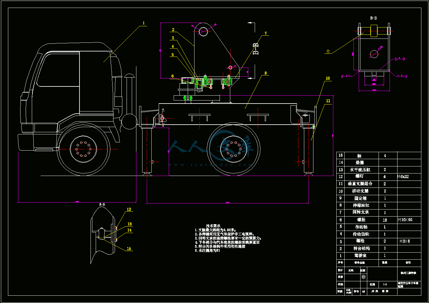
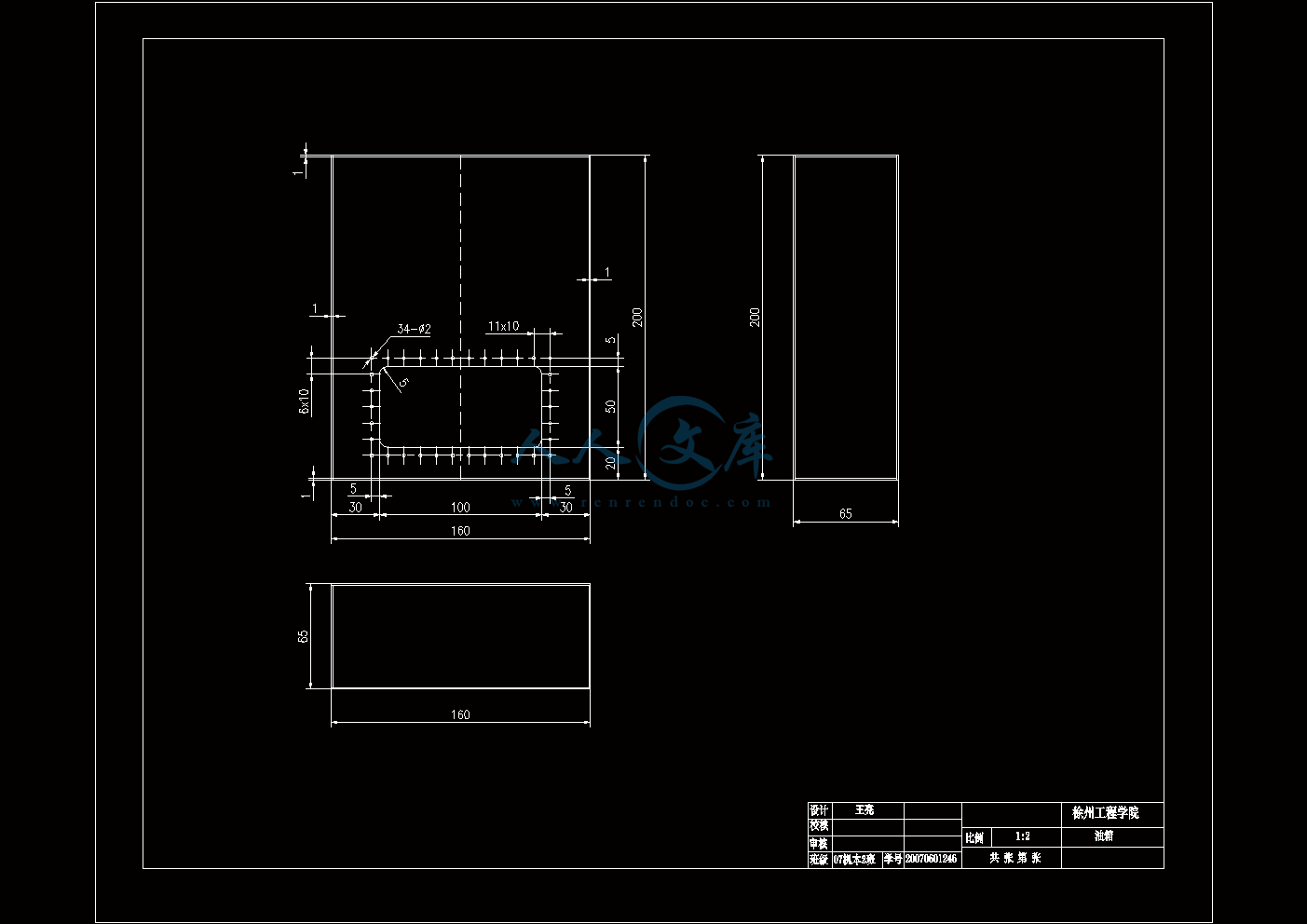
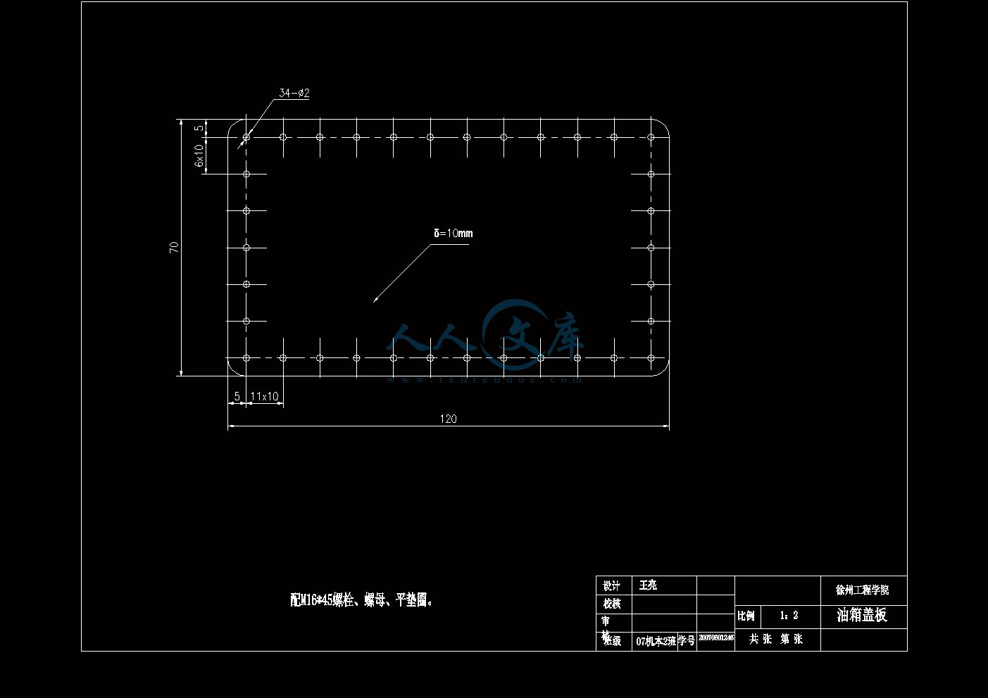
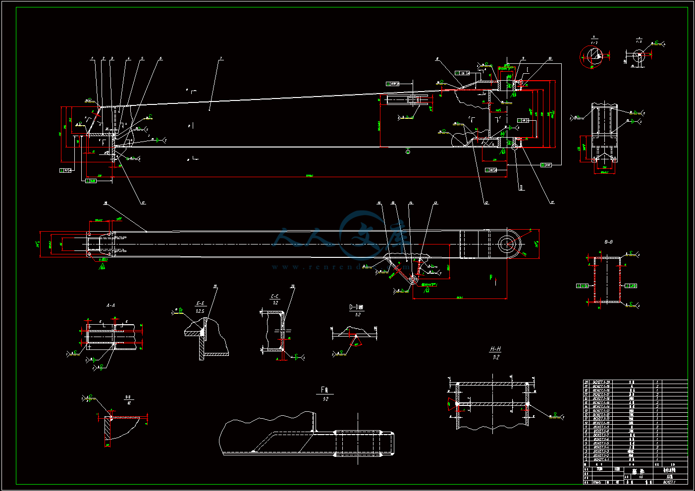
高空作业车下车装配图A0.dwg
高空作业车下车装配图A0.dwg

高空作业车下车部分设计【机+液】【8张图纸-3A0+毕业论文】【优秀】

收藏

压缩包内文档预览:
预览图
编号:421997    类型:共享资源    大小:1.72MB    格式:RAR    上传时间:2015-04-01 上传人:上*** IP属地:江苏
39
积分
关 键 词:
高空作业车 下车部分 设计 图纸 优秀
资源描述:

高空作业车下车的设计

50页 24000字数+说明书+外文翻译+8张CAD图纸【详情如下】

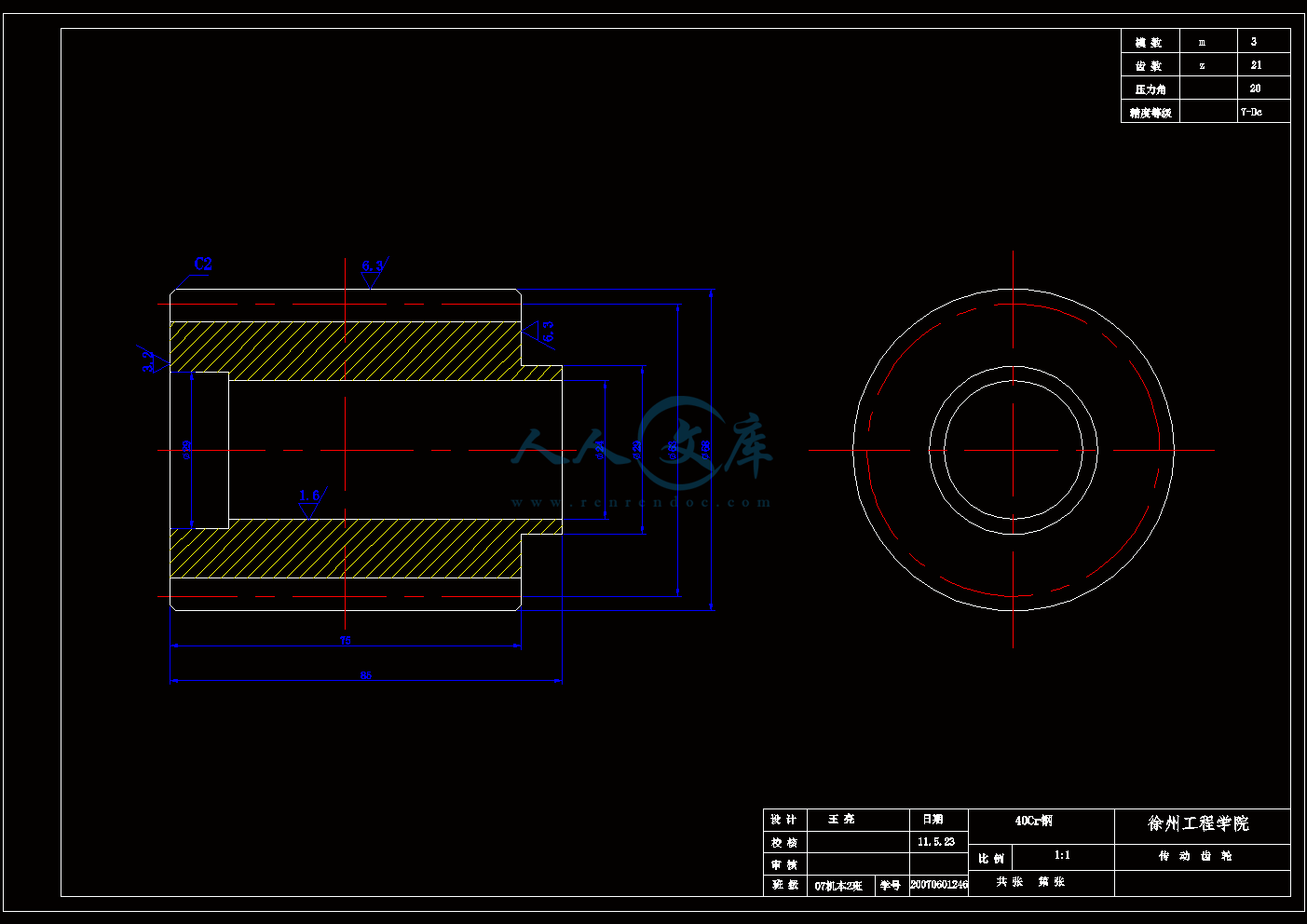
传动齿轮A2.dwg

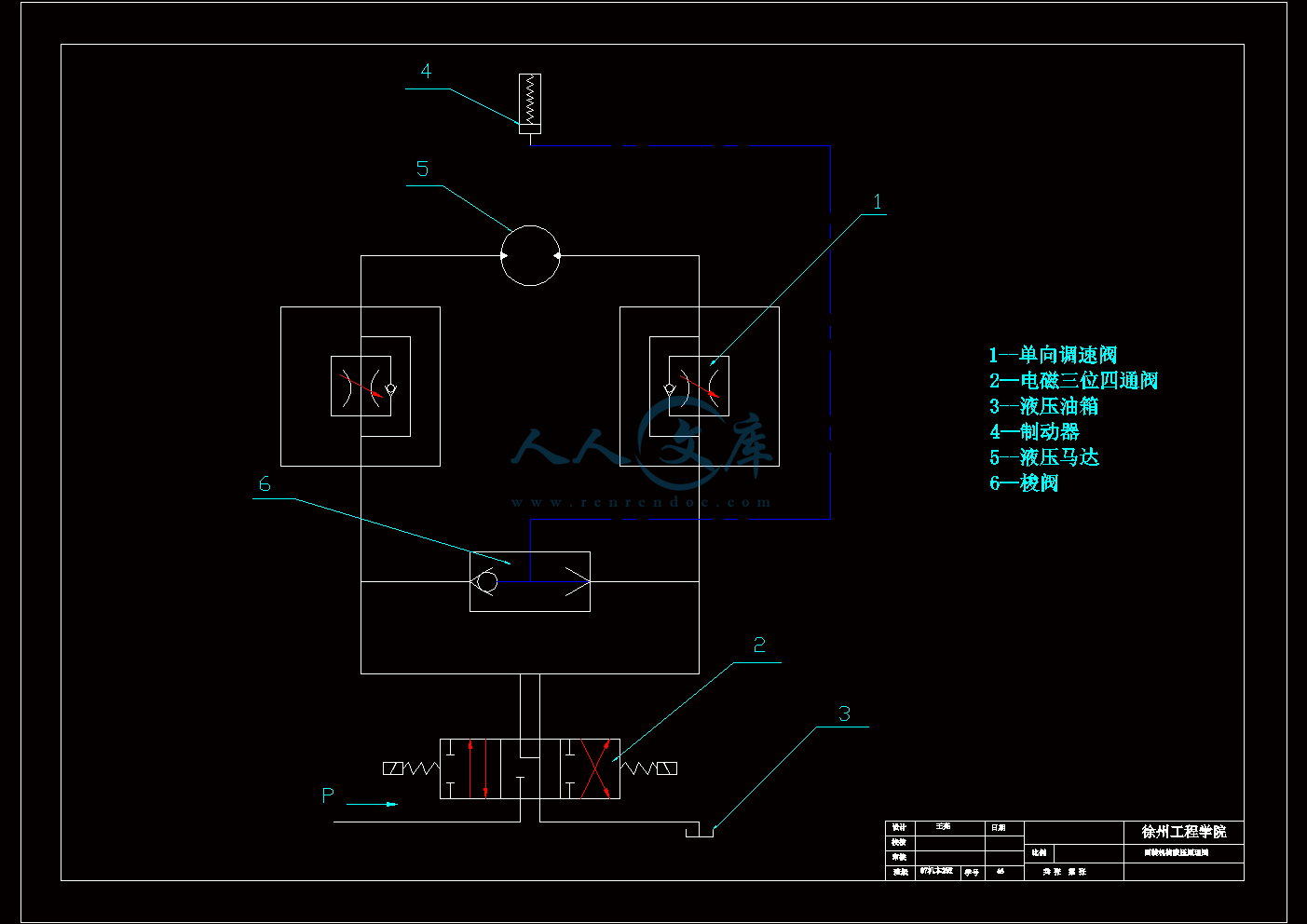
回转机构的液压原理图A2.dwg

外文翻译--浅谈油管液压管路系统设计.doc

支腿的液压原理图A2.dwg

支腿装配图A0.dwg

油箱A2.dwg

油箱盖板A2.dwg

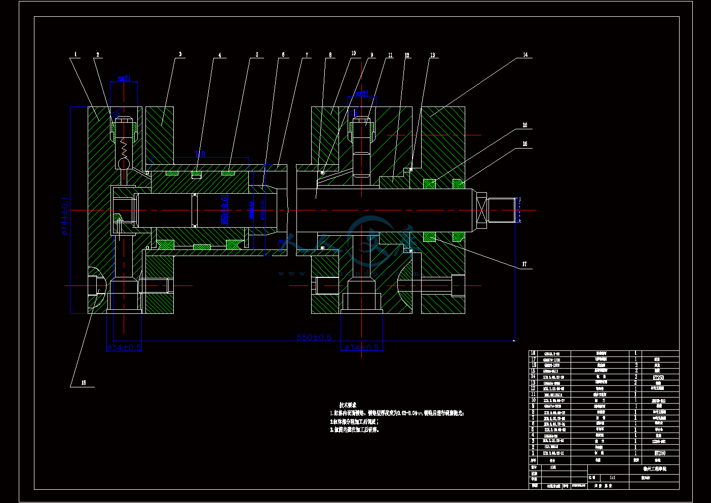
液压缸A2.dwg

高空作业车下车的设计论文.doc

高空作业车下车装配图A0.dwg
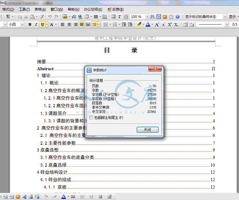
目录

摘要I

AbstractII

1 绪论1

1.1 概论1

1.2高空作业车的概况及市场的发展水平和前景1

1.2.1高空作业车的概况1

1.2.2高空作业车国内外的发展状况2

1.3课题简介4

1.3.1课题的背景和意义4

2 高空作业车的主要参数和构造6

2.1 高空作业车的主要构造6

2.2主要性能参数7

3底盘选型9

3.1高空作业车的底盘分类9

3.2底盘选择10

4转台结构设计12

4.1转台的组成12

4.1.1 底板12

4.1.2 转台的回转支承12

4.1.3传动齿轮15

4.1.4转台结构15

4.2回转支承装置的计算与选用16

4.2.1高空作业车的工况分析16

4.2.2转盘式回转支承装置的计算17

4.2.3按承载能力曲线选取合适的回转支承型号18

4.2.4选择传动齿轮18

4.2.5回转机构液压马达的设计21

5车架及支腿的选择设计与计算24

5.1副车架的结构分析24

5.1.1 几何约定将副车架的受力几何模型简化24

5.1.2 外载荷条件24

5.1.3副车架双纵梁门框结构的静力学计算24

5.2支腿的分类25

5.3支腿的受力分析25

5.4支腿的截面计算26

6液压系统的设计及液压元件的选择27

6.1液压系统类型27

6.1.1开式和闭式系统27

6.2液压控制系统27

6.2.1定量系统28

6.2.2变量系统28

6.3高空作业车下车的液压系统设计28

6.3.1各机构油路的组成及其特点28

6.3.2液压系统压力选择29

6.3.3液压回路设计29

6.4液压缸的选择31

6.4.1缸体与缸盖连接结构31

6.4.2活塞与活塞杆连接结构31

6.4.3活塞杆头部结构31

6.4.4导向套结构31

6.4.5密封与防尘结构32

6.4.6缓冲结构32

6.4.7液压缸的类型、主要材料及技术要求32

6.4.8垂直液压缸的选择33

6.4.10液压缸其他结构的设计37

6.5其他液压元件的选择37

6.5.1液压泵的选型与计算37

6.5.2阀的选择38

6.5.3 油箱的选择39

6.6液压系统主要性能验算39

6.6.1液压系统压力损失的验算39

6.6.2液压系统总效率的验算40

6.6.3液压系统发热温升的计算40

6.7液压油的性能要求41

结论42

致谢43

参考文献44

摘要

   高空作业车广泛用于建筑、市政、机场、工厂、园林、住宅等场所,从事消防、抢险、救灾、安装、维护等工作。高空作业车是将高空作业人员和必要的工具送至空中,并提供

工作人员空中作业场所的机械。

   本文首先介绍了高空作业车的现状,对高空作业车下车的各主要部分进行了分析和设计。主要包括了底盘的选型、回转机构的设计分析、支腿的设计、液压系统的设计以及液压元件的选择。本次设计的重点在于回转机构的设计与计算,回转机构采用液压马达,通过齿轮的啮合来实现转台的回转,支腿机构通过水平液压缸和垂直液压缸实现各支腿的收缩动作,采用并联控制系统实现各支腿的同时动作。

关键词  高空作业车;回转机构;液压系统

1 绪论

1.1 概论

在国家生产建设当中,大型的工程机械是不能缺少的技术设备,它在城市建设、交通运输、农田水利、能源开发和国防建设等各个方面都起着至关重要的作用。自从改革开放以后,国家加大了对基础设施的建设,以及引进了大量先进的国外技术设备、制造技术的,加速了整个工程机械行业的发展壮大。

高空作业车是一种用来运送工作人员和工作器材到达指定高度进行作业的工程机械。由于它具有安全可靠、机动灵活、操作简单等特点,因此在大型场馆、桥梁、港口海岸的检护;高层建筑的装饰、清洁与维护;通讯、供电及城市交通设施的安装与检修;影视作品的拍摄与现场直播;高空险境及近岸水面的脱困救生;树木的剪枝修整及药剂喷洒等方面被广泛地应用。

图1-1高空作业车在生活中的应用

1.2高空作业车的概况及市场的发展水平和前景

1.2.1高空作业车的概况

高空作业车用被称为高平台消防车,在市政、建筑、机场、电讯、工厂、住宅、园林

等场所被广泛应用,从事抢险救灾、消防、施工、安装、维护等工作。其中,最主要的一个功能就是让消防部门用于灭火、辅助灭火或消防救援。高空作业车是由将高空作业装置安装在汽车底盘上组成并用来运送工作人员和工作装备到指定高度进行作业的特种车辆。现在的高空作业装置具有自动调速、工作稳定、操作平顺、安全可靠等优点,极大地提高了空中作业的工作效率。

高空作业车按工作臂的型式,有四种基本型式(如图1-2),分别为:垂直升降式、折叠臂式、混合臂式和伸缩臂式。

垂直升降式高空作业车的升降机构只能在垂直方向上进行运动。它的主要特点是结构简单,承载能力强,但作业范围小,作业高度低,这种结构型式应用比较少。

折叠臂式高空作业车工作臂之间的连接全部采用铰接型式,所以国外又把它叫做铰接式高空作业车。折叠臂高空作业车结构适合于较低作业高度的车型,如要加大作业高度,必然要增加臂长或增加工作臂数量,增加臂长会使作业车体积庞大,降低灵活性;增加工作臂数量会造成操作繁琐,安全性降低。

伸缩臂式的高空作业车在行驶状态时,工作臂缩回套叠,工作时伸出,可以有效增大作业高度,同时具有工作效率高、操作简单、动作平稳等特点。

混合臂式高空作业车工作臂之间既有铰接,也有伸缩,是折叠臂式和伸缩臂式高空作业车的结合,它综合了两种结构型式的优点,工作性能最好,但结构也最为复杂。

高空作业车是利用汽车底盘作为行走机构,具有汽车的行驶通过性能,灵活机动,行

驶速度高,可以快速在转移到作业场地后迅速投入,是近几年来发展最快的一种国内专用

汽车产品。高空作业车这类高空作业器械是以工程起重机械为基础而发展起来的,高作业

设备广泛应用在建筑、消防、维护等行业。随着越来越高的作业高度,高空作业车振动所导致的大幅度摆动,定位的准确性受到了严重的影响,降低了工作效率,加之高空摆动给人的安全感极差,使得设备的宜人性也降低了,从而间接影响工作效率。因此针对高空作业车的动力系统研究有及其重要的意义。

内容简介:
Talking About The Design of Hydraulic ConductorsEric SandgrenThis paper is account for uncertainty Mechanical Engineering, University of California, San Francisco, avialon 503 West Main Street, P .O. Box9625311.1 INTRODUCTIONIn a hydraulic system, the fluid flows through a distribution system consisting of conductors and fittings, which carry the fluid from the reservoir through operating components and back to the reservoir. Since power is transmitted throughout the system by means of these conducting lines (conductors and fittings used to connect system components), it follows that they must be properly designed in order for the total system to function properly.The choice of which type of conductor to use depends primarily on the systems operating pressures and flow rates. In addition, the selection depends on environmental conditions such as the type of fluid, operating temperatures, vibration, and whether or not there is relative motion between connected components.Conducting lines are available for handling work pressures up to 10,000 Pa or greater. In general, steel tubing provides greater plumbing flexibility and neater appearance and requires fewer fittings than piping. However, piping is less expensive than steel tubing. Plastic tubing is finding increased industrial usage because it is not costly and circuits can be very easily hooked up due to its flexibility. Flexible hoses are used primarily to connect components that experience relative motion. They are made from a large number of elastomeric (rubberlike) compounds and are capable of handling pressures exceeding 10,000 Pa.Stainless steel conductors and fittings are used if extremely corrosive environments are expected. However, they are very expensive and should be used only if necessary. Copper conductors should not be used in hydraulic systems because the copper promotes the oxidation of petroleum oils. Zinc, magnesium, and cadmium conductors should not be used either because they are rapidly corroded by water-glycol fluids. Galvanized conductors should also be avoided because the galvanized surface has a tendency to flake off into the hydraulic fluid. When using steel pipe or steel tubing, hydraulic fittings should be made of steel except for inlet, return, and drain lines, where malleable iron may be used.Conductors and fittings must be designed with human safety in mind. They must be strong enough not only to withstand the steady-state system pressures but also the instantaneous pressure spikes resulting from hydraulic shock. Whenever control valves are closed suddenly, this stops the fluid, which possesses large amounts of kinetic energy. This produces shock waves whose pressure levels can be two or four times the steady-state system design values. Pressure spikes can also be caused by sudden stopping or starting of heavy loads. These high-pressure pulses are taken into account by the application of an appropriate factor of safety.1.2 CONDUCTOR SIZING FOR FLOW-RATE REQUIREMENTSA conductor must have a large enough cross-sectional area to handle the flow-rate requirements without producing excessive fluid velocity. Whenever we speak of fluid velocity in a conductor such as a pipe, we are referring to the average velocity. The concept of average velocity is important since we know that the velocity profile is not constant. As shown in Chapter 5 the velocity is zero at the pipe wall and reaches a maximum value at the centerline of the pipe. The average velocity is defined as the volume flow rate divided by the pipe cross-sectional area:In other words, the average velocity is that velocity which when multiplied by the pipe area equals the volume flow rate. It is also understood that the term diameter by itself always means inside diameter and that the pipe area is that area that corresponds to the pipe inside diameter. The maximum recommended velocity for pump suction lines is 4 ft/s (1.2 m/s) in order to prevent excessively low suction pressures and resulting pump cavitation. The maximum recommended velocity for pressure lines is 20 ft/s (6.1 m/s) in order to prevent turbulent flow and the corresponding excessive head losses and elevated fluid temperatures. Note that these maximum recommended values are average velocities.EXAMPLE 1-1A pipe handles a flow rate of 30 gprn. Find the minimum inside diameter that will provide an average fluid velocity not to exceed 20 ft/s.Solution Rewrite Eq. (3-26), solving for D:EXAMPLE 1-2A pipe handles a flow rate of 0.002. Find the minimum inside diameter that will provide an average fluid velocity not to exceed 6.1 m/s.Solution Per Eq. 3-35) we solve for the minimum required pipe flow area:The minimum inside diameter can now be found, becauseSolving for D we have1.3 PRESSURE RATING OF CONDUCTORSA conductor must be strong enough to prevent bursting due to excessive tensile stress (called hoop stress) in the wall of the conductor under operating fluid pressure. The magnitude of this tensile stress, which must be sustained by the conductor material. we see the fluid pressure ( P ) acting normal to the inside surface of a circular pipe having a length (L). The pipe has outside diameter D0 , inside diameter Di, and wall thickness t. Because the fluid pressure acts normal to the pipes inside surface, a pressure force is created that attempts to separate one half of the pipe from the other half.Figure shows this pressure forcepushing downward on the bottom half of the pipe. To prevent the bottom half of the pipe from separating from the upper half, the upper half pulls upward with a total tensile force F. One-half of this force ( or F/2 ) acts on the cross-sectional area (tL) of each wall, as shown.Since the pressure force and the total tensile force must be equal in magnitude, we havewhere A is the projected area of the lower half-pipe curved-wall surface onto a horizontal plane. Thus, A equals the area of a rectangle of width Di and length L, as shown in Figure 4-1(b). Hence,The tensile stress in the pipe material equals the tensile force divided by the wall cross-sectional area withstanding the tensile force. This stress is called a tensile stress because the force (F) is a tensile force (pulls on the area over which it acts).Substituting variables we havewhere = Greek symbol (sigma) = tensile stress.As can be seen from Eq. the tensile stress increases as the fluid pressure increases and also as the pipe inside diameter increases. In addition, as expected, the tensile stress increases as the wall thickness decreases, and the length of the pipe does not have any effect on the tensile stress.Burst Pressure and Working PressureThe burst pressure (BP) is the fluid pressure that will cause the pipe to burst. This happens when the tensile stress () equals the tensile strength ( S ) of the pipe material. The tensile strength of a material equals the tensile stress at which the material ruptures. Notice that an axial scribe line is shown on the pipe outer wall surface in Fig. 4-1(a). This scribe line shows where the pipe would start to crack and thus rupture if the tensile stress reached the tensile strength of the pipe material. This rupture will occur when the fluid pressure (P) reaches BR Thus, from Eq. (4-2) the burst pressure isThe working pressure (WP) is the maximum safe operating fluid pressure and is defined as the burst pressure divided by an appropriate factor of safety (FS).A factor of safety ensures the integrity of the conductor by determining the maximum safe level of working pressure. Industry standards recommend the following factors of safety based on corresponding operating pressures:FS = 8 for pressures from 0 to 1000 PaFS = 6 for pressures from 1000 to 2500 PaFS = 4 for pressures above 2500 PaFor systems where severe pressure shocks are expected, a factor of safety of 10 is recommended.Conductor Sizing Based on Flow Rate and Pressure ConsiderationsThe proper size conductor for a given application is determined as follows:1. Calculate the minimum acceptable inside diameter (Di) based on flow-rate requirements.2. Select a standard-size conductor with an inside diameter equal to or greater than the value calculated based on flow-rate requirements.3. Determine the wall thickness (t) of the selected standard-size conductor using the following equation:4. Based on the conductor material and system operating pressure (P), determine the tensile strength (S) and factor of safety (FS).5. Calculate the burst pressure (BP) and working pressure (WP) using Eqs. (4-3) and (4-4).6. If the calculated working pressure is greater than the operating fluid pressure, the selected conductor is acceptable. If not, a different standard-size conductor with a greater wall thickness must be selected and evaluated. An acceptable conductor is one that meets the flow-rate requirement and has a working pressure equal to or greater than the system operating fluid pressure.The nomenclature and units for the parameters of Eqs. BP = burst pressure (Pa, MPa)Di = conductor inside diameter (in., m)D0 = conductor outside diameter (in., m)FS = factor of safety (dimensionless)P = system operating fluid pressure (Pa, MPa)S = tensile strength of conductor material (Pa, MPa)t = conductor wall thickness (in., m)WP = working pressure (Pa, MPa)= tensile stress (Pa, MPa)EXAMPLE 1-3A steel tubing has a 1.250-in, outside diameter and a 1.060-in, inside diameter. It is made of SAE 1010 dead soft cold-drawn steel having a tensile strength of 55.000 Pa. What would he the safe working pressure for this tube assuming a factor of safety of 8?Solution First, calculate the wall thickness of the tubing:Next, find the burst pressure for the tubing:Finally, calculate the working pressure at which the tube can safely operate:Use of Thick-Walled ConductorsEquations and apply only for thin-walled cylinders where the ratio Di / t is greater than 10. This is because in thick-walled cylinders (Di / t 10), the tensile stress is not uniform across the wall thickness of the tube as assumed in the derivation of Eq. (4-2). For thick-walled cylinders Eq. (4-6) must be used to take into account the nonuniform tensile stress,Thus, if a conductor being considered is not a thin-walled cylinder, the calculations must be done using Eq. (4-6). As would be expected, the use of Eq. (4-6) results in a smaller value of burst pressure and hence a smaller value of working pressure than that obtained from Eq. (4-3). This can be seen by comparing the two equations and noting the addition of the 1.2t term in the denominator of Eq. (4-6).Note that the steel tubing of Example 4-3 is a thin-walled cylinder because = 1.060 in./0.095 in. =11.2 10. Thus, the steel tubing of Example 4-3 can operate safely with a working pressure of 1230 Pa as calculated using a factor of safety of 8. Using Eq. (4-6) for this same tubing and factor of safety yieldsAs expected the working pressure of 1110 Pa calcu1ated using Eq. (4-6) is less than the 1230 Pa value calculated in Example 4-3 using Eq. (4-3).1.4 STEEL PIPESSize DesignationPipes and pipe fittings are classified by nominal size and schedule number, as illustrated in Fig. 4-2. The schedules provided are 40, 80, and 160, which are the ones most commonly used for hydraulic systems. Note that for each nominal size the outside diameter does not change. To increase wall thickness the next larger schedule number is used. Also observe that the nominal size is neither the outside nor the inside diameter. Instead, the nominal pipe size indicates the thread size for the mating connections. The pipe sizes given in Fig. 4-2 are in units of inches.Figure 4-3 shows the relative size of the cross sections for schedules 40, 80, and 160 pipes. As shown for a given nominal pipe size, the wall thickness increases as the schedule number increases.Thread Design Pipes have tapered threads, as opposed to tube and hose fittings, which have straight threads. As shown in Fig. 4-4, the joints are sealed by an interference fit between the male and female threads as the pipes are tightened. This causes one of the major problems in using pipe. When a joint is taken apart, the pipe must be tightened farther to reseal. This frequently requires replacing some of the pipe with slightly longer sections, although this problem has been overcome somewhat by using Teflon tape to reseal the pipe joins. Hydraulic pipe threads are the dry-seal type. They differ from standard pipe threads because they engage the roots and crests before the flanks. In this way, spiral clearance is avoided.Pipes can have only male threads, and they cannot be bent around obstacles. There are, of course, various required types of fittings to make end connections and change direction, as shown in Fig. 4-5. The large number of pipe fittings required in a hydraulic circuit presents many opportunities for leakage, especially as pressure increases. Threaded-type fittings are used in sizes up to in. in diameter. Where larger pipes are required, flanges are welded to the pipe, as illustrated in Fig. 4-6. As shown, flat gaskets or 0-rings are used to seal the flanged fittings.1.5 STEEL TUBINGSize DesignationSeamless steel tubing is the most widely used type of conductor for hydraulic systems as it provides significant advantages over pipes. The tubing can be bent into almost any shape, thereby reducing the number of required fittings. Tubing is easier to handle and can be reused without any sealing problems. For low-volume systems, tubing can handle the pressure and flow requirements with less bulk and weight. However, tubing and its fittings are more expensive. A tubing size designation always refers to the outside diameter. Available sizes include-in. increments from -in. outside diameter up to -in. outside diameter. For sizes from-in. to 1 in. the increments are -in. For sizes beyond 1 in., the increments are-in. Figure 4-7 shows some of the more common tube sizes (in units of inches) used in fluid power systems.SAE 1010 dead soft cold-drawn steel is the most widely used material for tubing. This material is easy to work with and has a tensile strength of 55,000 Pa. If greater strength is required, the tube can be made of AISI 4130 steel, which has a tensile strength of 75,000 Pa.Tube FittingsTubing is not sealed by threads but by special kinds of fittings, as illustrated in Fig. 4-8. Some of these fittings are known as compression fittings. They seal by metal-to-metal contact and may be either the flared or flareless type. Other fittings may use 0-rings for sealing purposes. The 370 flare fitting is the most widely used fitting for tubing that can be flared. The fittings shown in Fig. seal by squeezing the flared end of the tube against a seal as the compression nut is tightened. A sleeve inside the nut supports the tube to dampen vibrations. The standard 450 flare fitting is used for very high pressures. It is also made in an inverted design with male threads on the compression nut. When the hydraulic component has straight thread ports, straight thread 0-ring fittings can be used, as shown in Fig. 4-8(c). This type is ideal for high pressures since the seal gets tighter as pressure increases.Two assembly precautions when using flared fittings are:1.The compression nut needs to be placed on the tubing before flaring the tube.2. These fittings should not be over-tightened. Too great a torque damages the sealing surface and thus may cause leaks.For tubing that cant be flared, or if flaring is to be avoided, ferrule, 0-ring, or sleeve compression fittings can be used see Fig. 4-8(d), (e), (f). The O-ring fitting permits considerable variations in the length and squareness of the tube cut.Figure 4-9 shows a Swagelok tube fitting, which can contain any pressure up to the bursting strength of the tubing without leakage. This type of fitting can be repeatedly taken apart and reassembled and remain perfectly sealed against leakage. Assembly and disassembly can be done easily and quickly using standard tools. In the illustration, note that the tubing is supported ahead of the ferrules by the fitting body. Two ferrules grasp tightly around the tube with no damage to the tube wall. There is virtually no constriction of the inner wall, ensuring minimum flow restriction. Exhaustive tests have proven that the tubing will yield before a Swagelok tube fitting will leak. The secret of the Swagelok fitting is that all the action in the fitting moves along the tube axially instead of with a rotary motion. Since no torque is transmitted from the fitting to the tubing, there is no initial strain that might weaken the tubing. The double ferrule interaction overcomes variation in tube materials, wall thickness, and hardness.In Fig. 4-10 we see the 450 flare fitting. The flared-type fitting was developed before the compression type and for some time was the only type that could successfully seal against high pressures.Four additional types of tube fittings are depicted in Fig. 4-11: (a) union elbow, (b) union tee, (c) union, and (d) 45 male elbow. With fittings such as these, it is easy to install steel tubing as well as remove it for maintenance purposes.EXAMPLE 1-4Select the proper size steel tube for a flow rate of 30 gpm and an operating pressure of 1000 Pa. The maximum recommended velocity is 20 ft/s, and the tube material is SAE 1010 dead soft cold-drawn steel having a tensile strength of 55,000 Pa,Solution The minimum inside diameter based on the fluid velocity limitation of 20 ft/s is the same as that found in Example 4-1 (0.782 in.).From Fig. 4-7, the two smallest acceptable tube sizes based on flow-rate requirements are1-in. od , 0.049-in, wall thickness, 0.902-in. ID1-in. od , 0.065-in, wall thickness, 0,870-in. IDLets check the 0.049-in, wall thickness tube first since it provides the smaller velocity:This working pressure is not adequate, so lets next examine the 0.065-in, wall thickness tube:This result is acceptable, because the working pressure of 1030 Pa is greater than the system-operating pressure of 1000 Pa and10.1.6 PLASTIC TUBINGPlastic tubing has gained rapid acceptance in the fluid power industry because it is relatively inexpensive. Also, it can be readily bent to fit around obstacles, it is easy to handle, and it can be stored on reels. Another advantage is that it can be color-coded to represent different parts of the circuit because it is available in many colors. Since plastic tubing is flexible, it is less susceptible to vibration damage than steel tubing.Fittings for plastic tubing are almost identical to those designed for steel tubing. In fact many steel tube fittings can be used on plastic tubing, as is the case for the Swagelok fitting of Fig. 4-9. In another design, a sleeve is placed inside the tubing to give it resistance to crushing at the area of compression, as illustrated in Fig. 4-12. In this particular design (called the Poly-Flo Flareless Tube Fitting), the sleeve is fabricated onto the fitting so it cannot be accidentally left off.Plastic tubing is used universally in pneumatic systems because air pressures are low, normally less than 100 Pa. Of course, plastic tubing is compatible with most hydraulic fluids and hence is used in low-pressure hydraulic applications.Materials for plastic tubing include polyethylene, polyvinyl chloride, polypropylene, and nylon. Each material has special properties that are desirable for specific applications. Manufacturers catalogs should be consulted to determine which material should be used for a particular application.1.7 FLEXIBLE HOSESDesign and Size DesignationThe fourth major type of hydraulic conductor is the flexible hose, which is used when hydraulic components such as actuators are subjected to movement. Examples of this are found in portable power units, mobile equipment, and hydraulically powered machine tools. Hose is fabricated in layers of elastomer (synthetic rubber) and braided fabric or braided wire, which permits operation at higher pressures.As illustrated in Fig. 4-13, the outer layer is normally synthetic rubber and serves to protect the braid layer. The hose can have as few as three layers (one being braid) or can have multiple layers to handle elevated pressures. When multiple wire layers are used, they may alternate with synthetic rubber layers, or the wire layers may be placed directly over one another.Figure 4-14 gives some typical hose sizes and dimensions for single-wire braid and double-wire braid designs. Size specifications for a single-wire braid hose represent the outside diameter in sixteenths of an inch of standard tubing, and the hose will have about the same inside diameter as the tubing. For example, a size 8 single-wire braid hose will have an inside diameter very close to a-in. standard tubing. For double-braided hose, the size specification equals the actual inside diameter in sixteenths of an inch. For example, a size 8 double-wire braid hose will have a-in. inside diameter. The minimum bend radii values provide the smallest values for various hose sizes to prevent undue strain or flow interference.Figure 4-15 illustrates five different flexible hose designs whose constructions are described as follows:a. FC 194: Elastomer inner tube, single-wire braid reinforcement, and elastomer cover Working pressures vary from 375 to 2750 Pa depending on the size.b.FC195: Elastomer inner tube, double-wire braid reinforcement, and elastomer cover. Working pressures vary from 1125 to 5000 Pa depending on the size.c.FC 300: Elastomer inner tube, polyester inner braid, single-wire braid reinforcement, and polyester braid cover. Working pressures vary from 350 to 3000 Pa depending on the size.d.1525: Elastomer inner tube, textile braid reinforcement, oil and mildew resistant, and textile braid cover. Working pressure is 250 Pa for all sizes.e.2791: Elastomer inner tube, partial textile braid, four heavy spiral wire reinforcements, and elastomer cover. Working pressure is 2500 Pa for all sizes.Hose FittingsHose assemblies of virtually any length and with various end fittings are available from manufacturers. See Fig. 4-16 for examples of hoses with the following permanently attached end fittings: (a) straight fitting, (b) 45 elbow fitting, and (c) 90 elbow fitting.The elbow-type fittings allow access to hard-to-get-at connections. They also permit better flexing and improve the appearance of the system.Figure 4-17 shows the three corresponding reusable-type end fittings. These types can be detached from a damaged hose and reused on a replacement hose. The renewable fittings idea had its beginning in 1941. With the advent of World War II, it was necessary to get aircraft with failed hydraulic lines back into operation as quickly as possible.Hose Routing and InstallationCare should be taken in changing fluid in hoses since the hose and fluid materials must be compatible. Flexible hose should be installed so there is no kinking during operation of the system. There should always be some slack to relieve any strain and allow for the absorption of pressure surges. It is poor practice to twist the hose and use long loops in the plumbing operation. It may be necessary to use clamps to prevent chafing or tangling of the hose with moving parts. If the hose is subject to rubbing, it should be encased in a protective sleeve. Figure 4-18 gives basic information on hose routing and installation procedures.1.8 QUICK DISCONNECT COUPLINGSOne additional type of fitting is the quick disconnect coupling used for both plastic tubing and flexible hose. It is used mainly where a conductor must be disconnected frequently from a component. This type of fitting permits assembly and disassembly in a matter of a second or two. The three basic designs are:1. Straight through: This design offers minimum restriction to flow but does not prevent fluid loss from the system when the coupling is disconnected.2.One-way shutoff: This design locates the shutoff at the fluid source connection but leaves the actuator component unblocked. Leakage from the system is not excessive in short runs, but system contamination due to the entrance of dirt in the open end of the fitting can be a problem, especially with mobile equipment located at the work site.3.Two-way shutoff: This design provides positive shutoff of both ends of pressurized lines when disconnected. See Fig.r a cutaway of this type of quick disconnect coupling. Figure 4-20 shows an external view of the same coupling. Such a coupling puts an end to the loss of fluids. As soon as you release the locking sleeve, valves in both the socket and plug close, shutting off flow. When connecting, the plug contacts an 0-ring in the socket, creating a positive seal. There is no chance of premature flow or waste due to a partial connection. The plug must be fully seated in the socket before the valves will open.1.9 METRIC STEEL TUBINGIn this section we examine common metric tube sizes and show how to select the proper size tube based on flow-rate requirements and strength considerations.Figure 4-21 shows the common tube sizes used in fluid power systems. Note that the smallest od size is 4 mm (0.158 in.), whereas the largest od size is 42 mm (1.663 in.). These values compare to 0.125 in. and 1.500 in., respectively, from Fig. 4-7 for common English units tube sizes. It should be noted that since 1 m = 39.6 in. then 1 mm = 0.0396 in.Factors of safety based on corresponding operating pressures becomeFS = 8 for pressures from 0 to 1000 Pa (0 to 7 MPa or 0 to 70 bars)FS = 6 for pressures from 1000 to 2500 Pa (7 to 17.5 MPa or 70 to 175 bars)FS = 4 for pressures above 2500 Pa (17.5 MPa or 175 bars)The corresponding tensile strengths for SAE 1010 dead soft cold-drawn steel and AISI 4130 steel are:SAE 101055,000 Pa or 379 MPaAISI 413075,000 Pa or 517 MPaEXAMPLE 1-5Select the proper metric size steel tube for a flow rate of 0.00190m3/s and an operating pressure of 70 bars. The maximum recommended velocity is 6.1 m/s and the tube material is SAE 1010 dead soft cold-drawn steel having a tensile strength of 379 MPa.Solution The minimum inside diameter based on the fluid velocity limitation of 6.1 rn/s is found using Eq. (3-18):Solving for A we have:Since we have the final resulting equation:Substituting values we have:From Fig. 4-21, the smallest acceptable od tube size is:22-mm od, 1.0-mm wall thickness, 20-mm IDFrom Eq. (4-3) we obtain the burst pressure.Then we calculate the working pressure using Eq. (4-4).This pressure is not adequate (less than operating pressure of 70 bars), so lets examine the next larger size od tube having the necessary ID.28-mm od, 2.0-mm wall thickness, 24-mm IDThis result is acceptable.浅谈油管液压管路系统设计Eric Sandgren 加州大学机械工程学院, avialon西部大街503号, 邮编962531, VA23284-3015收稿日期: 2003 年2月20日。1.1 简述在液压系统中, 液压油经过的系统包括管路和管接头, 这些液压油从油箱经过各机构的组成部分又回到油箱。因为在这过程中能量是通过这些管路传送到液压系统的各个部分(用来连接系统组分的管路和管接头), 所以为了总系统能够很好的发挥效率,必须进行恰当地设计。选用管路类型主要取决于系统的工作压力和流量。另外, 它的选择还取决于环境条件譬如油液的类型, 操作温度, 振动, 而且和连接部分之间是否有相对行动也有关系。管路可以通过的工作压力可以达到1000 Pa或者更大。一般情况下, 钢管材与管道相比,配管的灵活性更好、更加洁净而且管接头也比较少,更加的方便。但是, 用管道输送比钢管材较便宜。塑料管材因为它资源利用率高并且由于它的灵活性连接比较方便,增加了它的工业用途。软管主要用来连接相对行动组分的部分。它们由大量的弹性化合物组成,能处理超出10,000 Pa的压力 。在腐蚀性比较强的条件下一般使用不锈钢管路和管接头。但是, 它们比较昂贵, 只有在需要的情况下才可使用。铜管路不应该用在液压机构中,因为铜具有促进石油氧化作用。锌, 镁, 和钙管路也不应该被使用,因为由于水甘醇它们会迅速地被腐蚀掉。应该避免使用镀锌的管路,因为它的表面很容易剥落并且会融入液压液体。当使用钢管或钢管材, 液压管接头应该由钢制成除了一些回路等地方,这些地方可以使用铸铁。在设计管路和管接头时必须慎重地考虑它的安全性。它们必须具有足够的强度,不仅能够承受稳定系统压力而且还要承受由于液压震动而产生的瞬间压力。当控制阀突然被关闭时, 停止液压,这需要很多的动能。稳定系统设计时,应该考虑到这一过程可能需要二倍或四倍的冲击力。并且考虑由于突然停止或重载初可能造成的压力冲击。在设计时应该考虑到这些高压冲击的安全因素。1.2管路尺寸管路必须有一个足够大的面积,用来处理变速的要求。在一个管路中当我们谈到可变的速度譬如管子, 我们提到平均速度。因为速率是变化的所以平均速度的概念非常重要。依照速度是在管壁和在管子的中心线上达到一个最大值。由管子断面划分平均速度被定义为容量流速:换句话说, 平均速度是以管子合计容量流速的速度。一般被理解为流经管子最大内径的那个区积的速度。泵吸油管路的最大被允许速度为4ft/s (1.2 m/s),是为了防止压力太低同时引起泵的运转。规定可通过的最大流速是20 ft/s (6.1 m/s),这样是为了防止冲击、损失和油液的升温过大。规定这些最大值就是平均速度。例 1-1管子通过的流速是30gprn 。最小内径允许液压通过的平均速度不超出20 ft/ s 。解答 由式(3-26),求D:例 1-2通过管子的流量为0.002。求出可以通过平均速度低于6.1 m/ s的最小内径。解答 我们求得最小需要的管子截面积为:现在可以求出最小内径, 因为,可以求D为:1.3 管路压力规定值由于在液压运动下管路壁上会产生的强大压力(叫做强压),所以管路必须具有足够强度用来防止爆裂。这巨大的压力, 必须由管路材料承受, 由图4-1可确定。我们变化的压力(p) 相对一个圆管子的长度(l)。管子外径D0, 内径Di,并且壁厚为t。由于液压的压力一般在管子的内表面上,它试图把有压力的一半从管子的另外一半分离出来。显示这压力作用在管子的底下一半。为了防止管子的底下一半从上半方分离, 上半方总的向上的拉伸量为F。二分之一力(或F/2 )作用在各壁的断面(tL), 如显示。重要的是压力大小和总拉力必须是相等,可以有:A是管子曲壁表面区积平分线以下的一半。因而,均等宽度Di和长度L长方形的区积, 如上图4-1(b)。因此,作用在管子上的压力由壁断面划分承受的总力。这压力称压强,因为力(f) 是拉伸力(作用在它)的区积。替代变换我们可以求得: 这里= 希腊标志(斯格码)= 压强由式 (4-2)我们可以求得,当液压的压力增加,压强随着增加,当管子内径并且增加。 另外, 当管厚减小压强增加,并且管子的长度对压强没有任何影响。爆裂压力和工作压力爆裂压力(BP)是可以导致管子裂裂的液压的压力。当压强 ()大于抗拉强度(s)是 管子发生爆裂。材料爆裂的压强取决于材料的抗拉强度。注意,一个轴向划线被显示在管子外壁表面。这个划线行显示何处管子会发生崩裂和如果压强达到了管子的抗拉强度时材料因而爆裂。当液压压力(p)达到BR 时,这爆裂将发生。因而,由式(4-2) 爆裂压力是工作压力(WP) 是安全工作的最大液压压力并且被定义为划分了由爆裂压力安全(FS) 一个适当的因素。安全因素是保证管路的坚固用来确定工作压力的最高安全水平。根据对应的工作压力标准推荐下面的安全因素:FS=8 为压力从0 到1000 PaFS=6 为压力从1000 年到2500 PaFS=4 为压力在2500 Pa之上为了达到期望压力的系统, 规定10种安全因素。管路尺寸根据流速和压力考虑通过给定条件确定管路尺寸如下:1.根据流速要求计算最小内径(Di)。2.根据流速要求选择管路的标准内径大于或等于计算出来的值。3.由选出的标准使用以下等式确定壁厚(t):4.根据管路材料和系统工作压力(p), 确定抗拉强度(s)和安全因素(FS)。5. 由式(4-3)和(4-4)计算爆裂压力(BP) 和工作压力(WP) 。6. 如果计算的工作压力大于液压的工作压力, 选择的管路是可接受的。如果不是,必须重新选择管路的标准尺寸以及壁厚。一个可用的管路必须是一个符合流速要求和等于或大于系统的工作压力。命名原则和参量单位 式s(4-2), (4-3), (4-4),和(4-5)如下:BP=裂裂了压力(Pa, MPa)Di=管路内径(in., m)D0=管路外部直径(in., m)FS=安全因素(dimensionless)P=系统工作的可变压力(Pa, MPa)S=管路材料抗拉强度(Pa, MPa)t=管路壁厚(in., m)WP=工作压力(Pa, MPa)=压强(Pa, MPa)例1-3钢管材有外部直径a 1.250m,和内径a 1.060m。它由SAE 1010 冷制钢制成,抗拉强度有55.000 Pa。这支管会它安全工作压力为承担安全因素8?首先解答,计算管材的壁厚:其次,管材爆裂压力为:最后,计算管安全工作压力:厚壁管管路的用途只能允许厚壁圆筒比率Di/t大于10。这是因为在厚壁圆筒里(Di /t10), 依照式(4-2)假设拉力管的壁厚和管径不是一致的。式(4-6)为厚壁圆筒,使用时必须考虑到不均匀的拉力, 因而,如果考虑管路不是一个薄壁圆筒, 计算时必须使用式(4-6)。如被期望的那样,由式(4-6)计算比由式(4-3)计算,可以获得更小的爆裂压力和工作压力。这能比较二个等式并且注意发现在式(4-6)分母上加1.2t。注意钢管材例子4-3 是一个薄壁圆筒,因为=1.060/0.095=11.210。因而, 依照计算,钢管材例子4-3可以1230 Pa安全地工作,使用工作压力安全因素8。用式(4-6) 为这个同样管材和安全因素 例子用式(4-6)计算出来的工作压力为1110 Pa要比用式(4-3)计算出的1230 Pa更小。1.4 钢管管子和管子管接头划分不同的大小和数字,且提供有40,80,和160, 这些在液压机构中是最常用的几种。注意各个不同的大小它的外径是不改变的。为了增加壁厚,用下个更大的表中的数字。并且观察,外部和内径都是尺寸不想同的。同时,不同管子大小表明联接的螺纹尺寸。螺纹设计 管子逐渐变细螺纹,与管和管接头相对,有平直的螺纹。依照图4-4显示,当管子被拉紧,在两螺纹之间的接点由干涉被密封。这造成的最大问题是其中一个在使用管子。 当联接分开, 管子必须被拉紧重新密封。在细长的部分要求频繁地替换一些管子, 虽然这个问题由使用加入聚四氟乙烯磁带重新密封管子克服了一部分。液压管子螺纹是干燥密封类型。 它们从标准管子分出,因为在这之前它们参与了处理。这样,螺旋清除被避免了。管子可能有唯一主螺纹, 并且它们不能在障碍附近弯曲。当然也有各种各样的必需的管接头类型做终端连接和用来改变方向, 依照图4-5显示大量的管子管接头需要液压油路提供机会用来泄漏,特别是当压力增量时。穿线类型管接头被使用在尺寸达到直径的。耳轮缘焊接到管子上,这里是大管子必需的,在图4-6说明。根据显示 平的垫圈或0 圆环被使用密封被安装边缘的管接头。1.5 钢管材指定尺寸无缝的钢管材是广泛被应用的管路类型因为它为液压机构在管子上提供了非常大的好处。管材可以弯曲成任一形状,因此减少了一些必需的管
温馨提示:
1: 本站所有资源如无特殊说明,都需要本地电脑安装OFFICE2007和PDF阅读器。图纸软件为CAD,CAXA,PROE,UG,SolidWorks等.压缩文件请下载最新的WinRAR软件解压。
2: 本站的文档不包含任何第三方提供的附件图纸等,如果需要附件,请联系上传者。文件的所有权益归上传用户所有。
3.本站RAR压缩包中若带图纸,网页内容里面会有图纸预览,若没有图纸预览就没有图纸。
4. 未经权益所有人同意不得将文件中的内容挪作商业或盈利用途。
5. 人人文库网仅提供信息存储空间,仅对用户上传内容的表现方式做保护处理,对用户上传分享的文档内容本身不做任何修改或编辑,并不能对任何下载内容负责。
6. 下载文件中如有侵权或不适当内容,请与我们联系,我们立即纠正。
7. 本站不保证下载资源的准确性、安全性和完整性, 同时也不承担用户因使用这些下载资源对自己和他人造成任何形式的伤害或损失。
提示  人人文库网所有资源均是用户自行上传分享,仅供网友学习交流,未经上传用户书面授权,请勿作他用。
关于本文
本文标题:高空作业车下车部分设计【机+液】【8张图纸-3A0+毕业论文】【优秀】
链接地址:https://www.renrendoc.com/p-421997.html

官方联系方式

2:不支持迅雷下载,请使用浏览器下载   
3:不支持QQ浏览器下载,请用其他浏览器   
4:下载后的文档和图纸-无水印   
5:文档经过压缩,下载后原文更清晰   
关于我们 - 网站声明 - 网站地图 - 资源地图 - 友情链接 - 网站客服 - 联系我们

网站客服QQ:2881952447     

copyright@ 2020-2025  renrendoc.com 人人文库版权所有   联系电话:400-852-1180

备案号:蜀ICP备2022000484号-2       经营许可证: 川B2-20220663       公网安备川公网安备: 51019002004831号

本站为文档C2C交易模式,即用户上传的文档直接被用户下载,本站只是中间服务平台,本站所有文档下载所得的收益归上传人(含作者)所有。人人文库网仅提供信息存储空间,仅对用户上传内容的表现方式做保护处理,对上载内容本身不做任何修改或编辑。若文档所含内容侵犯了您的版权或隐私,请立即通知人人文库网,我们立即给予删除!