井下探测救援机器人平台结构设计【任务书+开题+翻译】【5张图纸】【优秀】
收藏
资源目录

压缩包内文档预览:
编号:422832
类型:共享资源
大小:1.34MB
格式:RAR
上传时间:2015-04-07
上传人:上***
认证信息
个人认证
高**(实名认证)
江苏
IP属地:江苏
39
积分
- 关 键 词:
-
井下
探测
救援
机器人
平台
结构设计
任务书
开题
翻译
图纸
井下探测救援
探测救援机器人
- 资源描述:
-
井下探测救援机器人平台结构设计
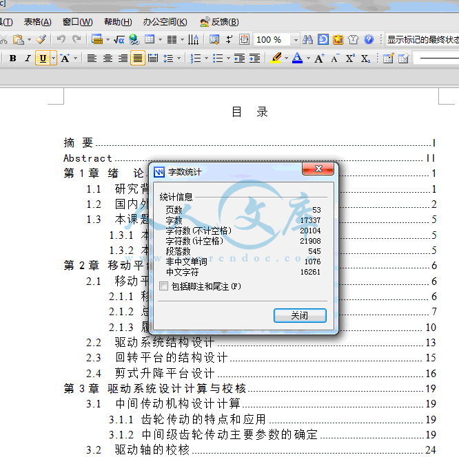
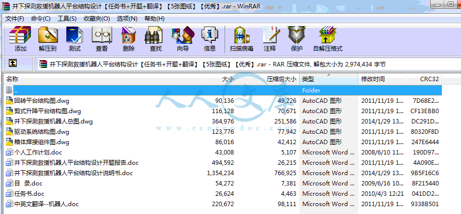
53页 17000字数+说明书+任务书+开题报告+中英文翻译+6张CAD图纸【详情如下】
个人工作计划.doc
中英文翻译--机器人.doc
井下探测救援机器人平台结构设计开题报告.doc
井下探测救援机器人平台结构设计说明书.doc
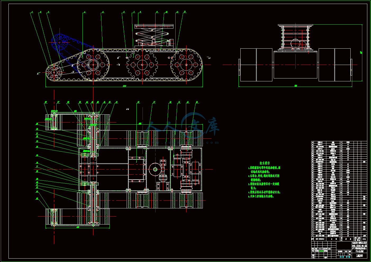
井下探测救援机器人总图.dwg
任务书.doc
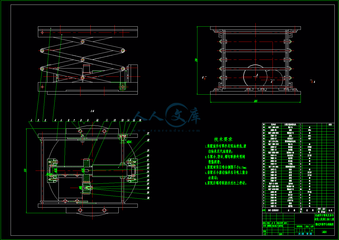
剪式升降平台结构图.dwg
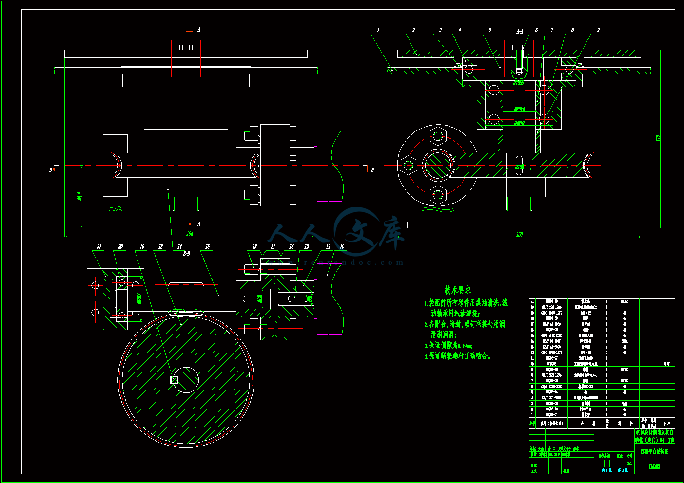
回转平台结构图.dwg
目 录.doc
箱体焊接组件图.dwg
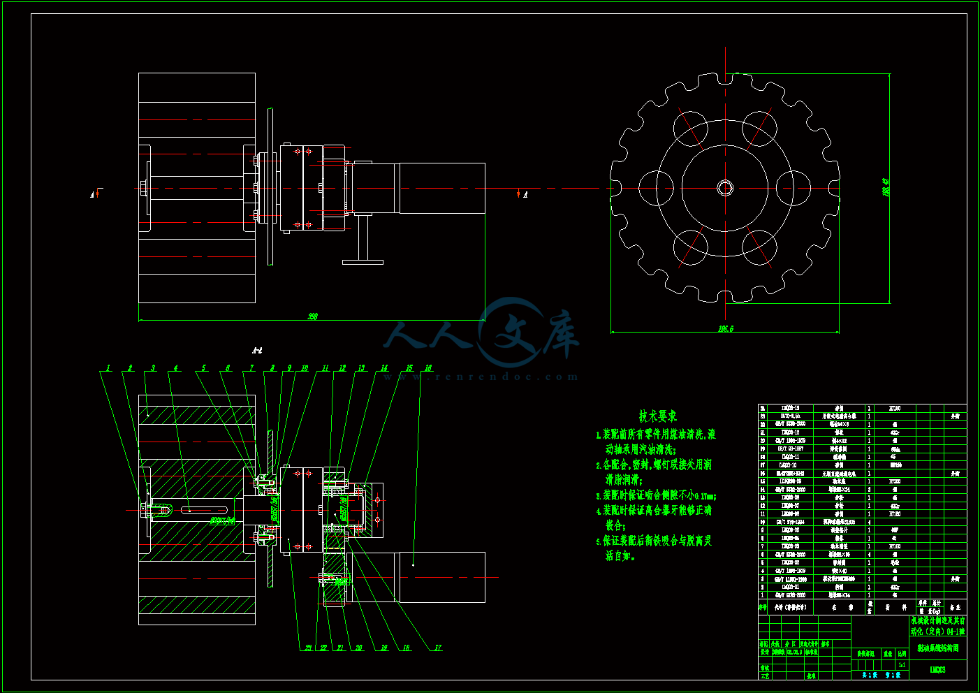
驱动系统结构图.dwg


目 录
摘 要I
AbstractII
第1章 绪 论1
1.1 研究背景1
1.2 国内外发展现状2
1.3 本课题的研究内容5
1.3.1 本课题的任务要求5
1.3.2 本课题的研究内容5
第2章 移动平台结构设计6
2.1 移动平台总体结构设计6
2.1.1 移动方式的选择6
2.1.2 总体结构方案的确定7
2.1.3 履带底盘总体基本尺寸的确定10
2.2 驱动系统结构设计13
2.3 回转平台的结构设计15
2.4 剪式升降平台设计16
第3章 驱动系统设计计算与校核19
3.1 中间传动机构设计计算19
3.1.1 齿轮传动的特点和应用19
3.1.2 中间级齿轮传动主要参数的确定19
3.2 驱动轴的校核24
3.2.1 驱动轴结构设计25
3.2.2 驱动轮轴受力分析25
3.2.3 驱动轴强度的校核28
第4章 履带机器人的运动学与动力学分析32
4.1 履带机器人的运动学分析32
4.1.1 移动平台运动坐标系的建立32
4.1.2 运动学模型33
4.1.3 逆运动模型35
4.2 移动平台动力学分析36
4.2.1 移动机器人运动机理研究36
4.2.2 电机的选择37
4.2.3 移动平台在正常环境下行驶分析38
4.2.4 机器人爬坡行驶分析39
4.2.5 机器人越障过程分析40
4.2.6 机器人越沟槽分析42
4.2.7 机器人行走抗倾覆状态分析44
第5章 经济技术分析45
结 论46
致 谢47
参 考 文 献48
附录 150
附录 254
摘 要
灾害发生之后为了能够尽快地搜救被困人员,人们开发了各种各样的灾害生命搜索定位设备,搜救机器人就是其中的一种。搜救机器人的应用涉及到搜救策略和搜救机器人本体技术开发两个问题,这两个方面的不断研究将共同推动搜救机器人的应用和发展。搜救机器人使用策略的首要问题就是如何选用搜救机器人的问题。当前世界各国正在开发了各式各样的灾害搜救机器人,然而到目前为止这些机器人系统还没有一套明确统一的描述标准和评价办法,这给如何选择使用合适的机器人参与具体的救援行动带来了很大的困难。煤矿搜救机器人本身的研究和开发,也是当前煤矿救援研究的重点方向之一。本文详细介绍了履带式复杂地形机器人平台结构的组成。首先对履带机器人移动平台的总体结构进行设计,从而设计了移动平台的驱动系统结构,同时考虑了机器人移动平台的通用性,设计了回转平台结构和升降机构,以便机器人能够适应不同的环境的工作。本文还对驱动系统中间传动机构进行了设计计算和校核。从机器人的行走条件入手,建立其运动模型,对机器人行走系的运动学与动力学进行分析,对运行及越障过程和抗倾覆能力进行分析研究。通过分析计算本设计能够满足设计要求,为下一步深入研究奠定了基础。
关键词 救援 机器人 履带 传动机构
1.3 本课题的研究内容
1.3.1 本课题的任务要求
本设计的任务是研究井下探测救援机器人移动平台的结构设计,其具体性能指标为:
1.垂直越障高度为0.3m;
2.最大爬坡角度不小于40°;
3.最大进退速度不小于0.5m/s;
4.最大跨沟槽宽度400mm;
5.机器人平台和搭载装置总重不超过40kg。
1.3.2 本课题的研究内容
1.机器人移动平台的总体结构设计;
2.移动平台驱动系统结构设计;
3.回转平台的设计;
4.升降机构的设计;
5.移动平台运动与动力学分析。
- 内容简介:
-
附录 1机器人工业机器人是在生产环境中用以提高生产效率的工具,它能做常规的装配线工作,或能做那些对于工人来说是危险的工作,例如,第一代工业机器人是用来在核电站中更换核燃料棒,如果人去做这项工作,将会遭受有害放射线的辐射。工业机器人亦能工作在装配线上将小元件装配到一起,如将电子元件安装在电路印刷板,这样,工人就能从这项乏味的常规工作中解放出来。机器人也能按程序要求用来拆除炸弹,辅助残疾人,在社会的很多应用场合履行职能。机器人可以认为是将手臂末端的工具、传感器和(或)手爪移到程序指定位置的一种机器。当机器人到达位置后,他将执行某种任务。这些任务可以是焊接、密封、机器装料、拆卸以及装配工作。除了编程以及系统的开停之外,这些工作可以在无人干预下完成。如下叙述的是机器人系统基本术语:机器人是一个可编程、多功能的机器手,通过给要完成的不同任务编制各种动作,它可以移动零件、材料、工具以及特殊装置。这个基本定义引导出后续段落的其他定义,从而描绘出一个完整的机器人系统。预编程位置点是机器人为完成工作而必须跟踪的轨迹。在某些位置点上机器人将停下来做某写操作,如装配零件、喷涂油漆或焊接。这些预编程点贮存在机器人的贮存器中,并为后续的连续操作所调用,而且这些预编程点像其他程序数据一样,可在日后随工作需要而变化。因而,正是这种可编程的特征,一个工业机器人很像一台计算机,数据可在这里储存、后续调用与编辑。机械手上机器人的手臂,它使机器人能弯曲、延伸、和旋转,提供这些运动的是机器手的轴,亦是所谓的机器人的自由度。一个机器人能有316轴,自由度一词总是与机器人轴数相关。工具和手爪不是机器人自身组成部分,但它们安装在机器人手臂末端的附件。这些连在机器人手臂末端的附件可使机器人抬起工件、点焊、刷漆、电弧焊、钻孔、打毛刺以及根据机器人的要求去做各种各样的工作。机器人系统还可以控制机器人的工作单元,工作单元是机器人执行任务所处的整体环境,包括控制器、机械手、工作平台、安全保护装置或者传输装置。所有这些为保证机器人完成自己任务而必需的装置都包括在这一工作单元中。另外,来自外设的信号与机器人通讯,通知机器人何时装配工件、取工件或放工件到传输装置上。机器人系统有三个基本部件:机械手、控制器和动力源。A.机械手机械手做机器人系统中粗重工作,它包括两个部分:机构和附件,机械手也有联接附件基座,图1表示了一机器人基座与附件之间的联接情况。图1机械手基座通常在工作区域的地基上,有时基座也可以移动,在这种情况下基座安装在导轨或轨道上,允许机械手从一个位置移动到另外一个位置。正如前面所提到的那样,附件从机器人基座上延伸出来,附件就是机器人的手臂,它可以是直接型,也可以是轴节型手臂,轴节型手臂也是大家所知的关节型手臂。机械臂使机械手产生各轴的运动。这些轴连在一个安装基座上,然后再连到托架上,托架确保机械手停留在某一位置。在手臂的末端上,连接着手腕(图1),手腕由辅助轴和手腕凸缘组成,手腕是让机器人用户在手腕凸缘上安装不同工具来做不同种工作。机械手的轴使机械手在某一区域内执行任务,我们将这个区域为机器人的工作单元,该区域的大小与机器手的尺寸相对应,(图2)列举了一个典型装配机器人的工作单元。随着机器人机械结构尺寸的增加。工作单元的范围也必须相应增加。图2机械手的运动由执行元件或驱动系统来控制。执行元件或驱动系统允许个轴在工作单元内运动。驱动系统可用电气、液压和气压动力,驱动系统所产生的动力经机构转变为机械能,驱动系统与机械传动链相匹配。有链、齿轮和滚珠丝杠组成的机械传动链驱动着机器人的各轴。B.控制器机器人控制器是工作单元的核心。控制器储存着预编程序供调用、控制外设,及与厂内计算进行通讯以满足产品经常更新的需要。控制器用于控制机器手运动和在工作单元内控制机器人外设。用户可通过手持的示教盒将机械手运动的程序编入控制器。这些信息储存在控制器的存储器中以备后续调用,控制器储存了机器人系统的所有编程数据,它能储存几个不同的程序,并且所有这些程序均能编辑。控制器要求能够在工作单元内外设进行通信。例如控制器有一个输入端,它能标识某个机加工操作何时完成。当该加工循环完成后,输入端接通,告诉控制器定位机械手以便能抓取已加工工件,随后,机械手抓取一未加工件,将其放置在机床上。接着,控制器给机床发出开始加工的信号。控制器可以由根据事件顺序而步进的机械式轮鼓组成,这种类型的控制器可用在非常简单的机械系统中。用于大多数人系统中的控制器代表现代电子学的水平,是更复杂的装置,即它们是由微处理器操纵的。这些微处理器可以是8位,16位或32位处理器。它们可以使得控制器在操纵工程中显非常柔性。控制器能通过通信线发送信号,使它能与机械手各轴交流信息,在机器人的机械手和控制器之间的双向交流信息可以保持操作和位置经常更新,控制器亦能控制安装在机器人手腕上的任何工具。控制器也有与厂内各计算机进行通信的任务,这种通信联系使机器人成为计算机辅助制造( CAM)系统的一个组成部分。存储器。基于微处理器的系统运行时要与固态的存储装置相连,这些存储装置可以是磁泡,随机存储器 、软盘、磁带等。每种记忆存储装置均能贮存、编辑信息以备后续调用和编辑。C.动力源动力源是给机器人和机器手提供动力的单元。传给机器人系统的动力源有两种,一种是用于控制器的交流电,另一种是用于驱动机械手各轴的动力源,例如,如果机器人的机械手是有液压和气动驱动的,控制信号便传送到这些装置中,驱动机器人运动。对于每一个机器人系统,动力是用来操纵机械手的。这些动力可来源与液压动力源、气压动力源或电源,这些能源是机器人工作单元整体的一部分。附录 2robotThe industrial robot is a tool that is used in the manufacturing environment to increase productivity. It can be used to do routine and tedious assembly line jobs, or it can perform jobs that might be hazardous to the human worker . For example ,one of the first industrial robot was used to replace the nuclear fuel rods in nuclear power plants. A human doing this job might be exposed to harmful amounts of radiation. The industrial robot can also operate on the assembly line, putting together small components, such as placing electronic components on a printed circuit board. Thus, the human worker can be relieved of the routine operation of this tedious task. Robots can also be programmed to defuse bombs, to serve the handicapped, and to perform functions in numerous applications in our society.The robot can be thought of as a machine that will move an end-of-tool ,sensor ,and/or gripper to a preprogrammed location. When the robot arrives at this location, it will perform some sort of task .This task could be welding, sealing, machine loading ,machine unloading, or a host of assembly jobs. Generally, this work can be accomplished without the involvement of a human being, except for programming and for turning the system on and off.The basic terminology of robotic systems is introduced in the following:1.A robot is a reprogrammable ,multifunctional manipulator designed to move parts,material,tool,or special devices through variable programmed motions for the performance of a variety of different task. This basic definition leads to other definitions, presented in the following paragraphs, that give a complete picture of a robotic system.2. Preprogrammed locations are paths that the robot must follow to accomplish work, At some of these locations, the robot will stop and perform some operation ,such as assembly of parts, spray painting ,or welding .These preprogrammed locations are stored in the robots memonry and are recalled later for continuous operation.Forthermore,these preprogrammed locations, as well as other program data, can be changed later as the work requirements change.Thus,with regard to this programming feature,an industrial robot is very much like a computer ,where data can be stoned and later recalled and edited.3. The manipulator is the arm of the robot .It allows the robot to bend,reach,and twist.This movement is provided by the manipulators axes,also called the degrees of freedom of the robot .A robot can have from 3 to 16 axes.The term degrees of freedom will always relate to the number of axes found on a robot.4. The tooling and frippers are not part the robotic system itself;rather,they are attachments that fit on the end of the robots arm. These attachments connected to the end of the robots arm allow the robot to lift parts,spot-weld ,paint,arc-weld,drill,deburr,and do a variety of tasks,depending on what is required of the robot.5. The robotic system can control the work cell of the operating robot.The work cell of the robot is the total environment in which the robot must perform its task.Included within this cell may be the controller ,the robot manipulator ,a work table ,safety features,or a conveyor.All the equipment that is required in order for the robot to do its job is included in the work cell .In addition,signals from outside devices can communicate with the robot to tell the robot when it should parts,pick up parts, or unload parts to a conveyor. The robotic system has three basic components: the manipulator, the controller, and the power sourse.A.Manipulator The manipulator ,which does the physical work of the robotic system,consists of two sections:the mechanical section and the attached appendage.The manipulator also has a base to which the appendages are attached.Fig.1 illustrates the connection of the base and the appendage of a robot.Photo 1.Basic components of a robots manipulatorThe base of the manipulator is usually fixed to the floor of the work area. Sometimes, though, the base may be movable. In this case, the base is attached to either a rail or a track,allowing the manipulator to be moved from one location to anther.As mentioned previously ,the appendage extends from the base of the robot. The appendage is the arm of the robot. It can be either a straight ,movable arm or a jointed arm. The jointed arm is also known as an articulated arm.The appendages of the robot manipulator give the manipulator its various axes of motion. These axes are attached to a fixed base ,which, in turn, is secured to a mounting. This mouning ensures that the manipulator will in one location.At the end of the arm , a wrist(see Fig 2)is connected. The wrist is made up of additional axes and a wrist flange. The wrist flange allows the robot user to connect different tooling to the wrist for different jobs.The manipulators axes allow it to perform work within a certain area. The area is called the work cell of the robot ,and its size corresponds to the size of the manipulator.(Fid2)illustrates the work cell of a typical assembly robot.As the robotsphysical size increases,the size of the work cell must also increase.Photo2.Elements of a work cell from the topThe movement of the manipulator is controlled by actuator,or drive systems.The actuator,or drive systems,allows the various axes to move within the work cell. The drive system can use electric,hydraulic,or pneumatic power.The energy developed by the drive system is converted to mechanical power by various mechanical power systems.The drive systems are coupled through mechanical linkages.These linkages,in turn,drive the different axes of the robot.The mechanical linkages may be composed of chain,gear,and ball screws.B.ControllerThe controller in the robotic system is the heart of the operation .The controller stores preprogrammed information for later recall,controls peripheral devices,and communicates with computers within the plant for constant updates in production.The controller is used to control the robot manipulators movements as well as to control peripheral components within the work cell. The user can program the movements of the mamipulator into the controller through the use of a hard-held teach pendant.This information is stored in the memory of the controller for later recall.The controller stores all program data for the robotic system.It can store several different programs,and any of these programs can be edited.The controller is also required to communicate with peripheral equipment within the work cell. For example,the controller has an input line that identifies when a machining operation is completed.When the machine cycle is completed,the input line turn on telling the controller to position the manipulator so that it can pick up the finidshed part.Then ,a new part is picked up by the manipulator and placed into the machine.Next,the controller signals the machine to srart operation.The controller can be made from mechanically operated drums that step through a sequence of enents.This type of controller operates with a very simple robotic system.The comtrollers found on the majority of robotic systems are more complex devices and represent state-of-the-art eletronoics.That is,they are microprocessor-operated.these microprocessors are either 8-bit,16-bit,or 32-bit processors.this power allows the controller to be very flexible in its operation.The controller can send electric signals over communication lines that allow it to talk with the various axes of the manipulator. This two-way communication between the robot manipulator and the controller maintains a constant update of the end the operation of the system.The controller also controls any tooling placed on the end of the robots wrist.The controller also has the job of communicating with the different plant computers. The communication link establishes the robot as part a computer-assisted manufacturing (CAM)
- 温馨提示:
1: 本站所有资源如无特殊说明,都需要本地电脑安装OFFICE2007和PDF阅读器。图纸软件为CAD,CAXA,PROE,UG,SolidWorks等.压缩文件请下载最新的WinRAR软件解压。
2: 本站的文档不包含任何第三方提供的附件图纸等,如果需要附件,请联系上传者。文件的所有权益归上传用户所有。
3.本站RAR压缩包中若带图纸,网页内容里面会有图纸预览,若没有图纸预览就没有图纸。
4. 未经权益所有人同意不得将文件中的内容挪作商业或盈利用途。
5. 人人文库网仅提供信息存储空间,仅对用户上传内容的表现方式做保护处理,对用户上传分享的文档内容本身不做任何修改或编辑,并不能对任何下载内容负责。
6. 下载文件中如有侵权或不适当内容,请与我们联系,我们立即纠正。
7. 本站不保证下载资源的准确性、安全性和完整性, 同时也不承担用户因使用这些下载资源对自己和他人造成任何形式的伤害或损失。

人人文库网所有资源均是用户自行上传分享,仅供网友学习交流,未经上传用户书面授权,请勿作他用。
 川公网安备: 51019002004831号