说明书.doc

立辊轧机侧压系统设计【6张图纸】【优秀】

收藏

压缩包内文档预览:(预览前20页/共49页)
预览图 预览图 预览图 预览图 预览图 预览图 预览图 预览图 预览图 预览图 预览图 预览图 预览图 预览图 预览图 预览图 预览图 预览图 预览图 预览图
编号:423407    类型:共享资源    大小:2.26MB    格式:RAR    上传时间:2015-04-08 上传人:上*** IP属地:江苏
39
积分
关 键 词:
立辊轧机 侧压系统 设计 图纸 立辊轧机侧压系统
资源描述:

立辊轧机侧压系统设计

52页 13000字数+说明书+外文翻译+5张CAD图纸【详情如下】

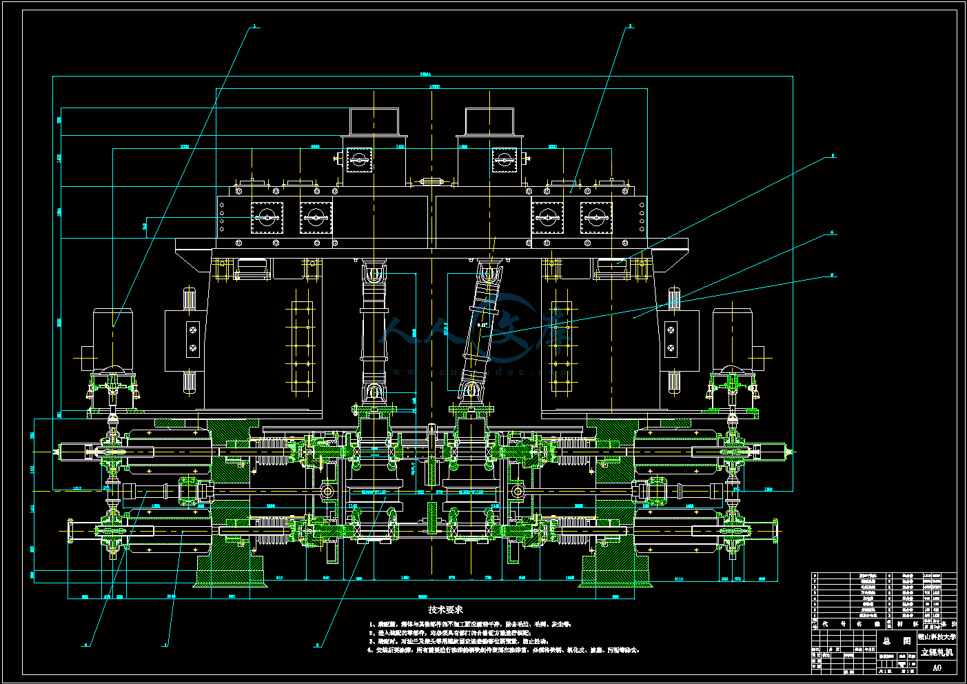
A0总装图.dwg

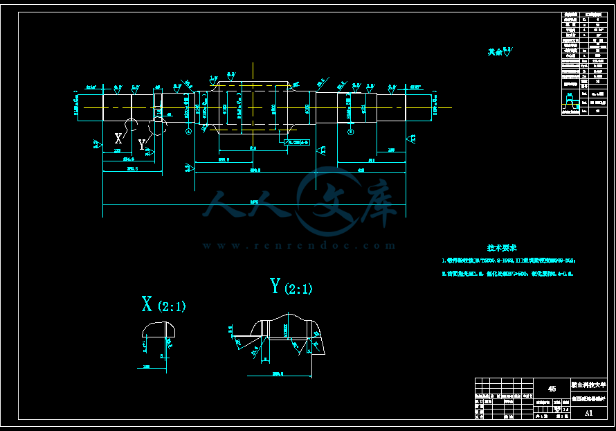
A0立辊.dwg

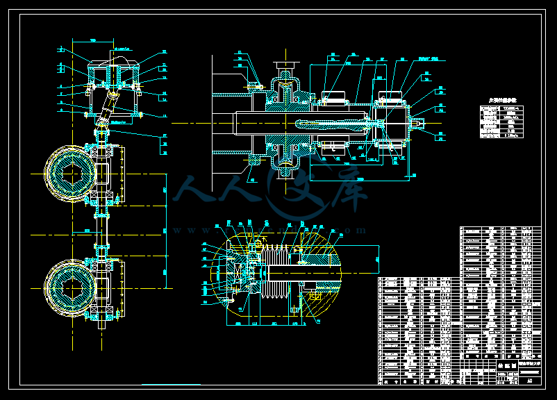
A0辊缝调整装配图.dwg

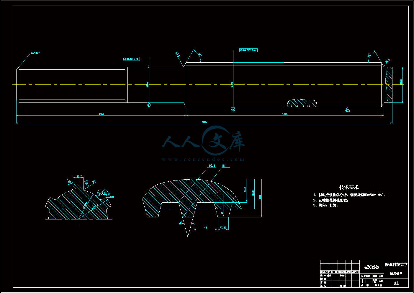
A1侧压螺丝.dwg

A1蜗杆.dwg

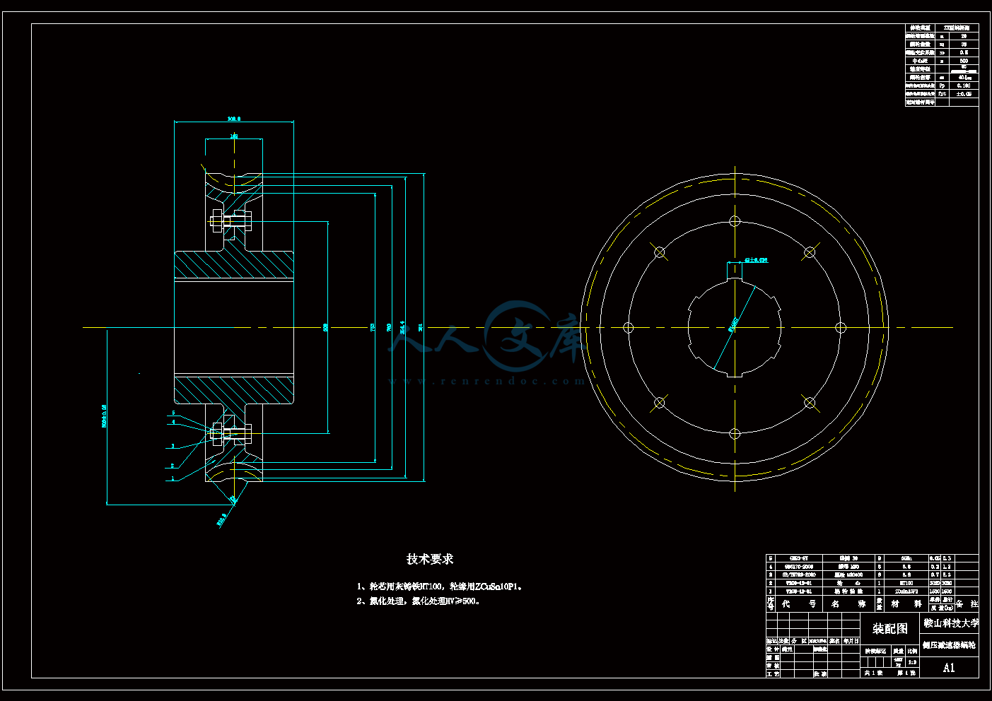
A1蜗轮.dwg

外文翻译--20-h冷轧机的模型化和优化.doc

摘要.doc

新技术专题封面.doc

热轧立辊轧机的改进.doc

立辊轧机侧压系统设计说明书.doc

说明书.doc
目录

1绪论4

1.1 立辊轧机的用途和结构特点4

1.2 立辊轧机的国内外发展现状4

2 总体方案确定7

2.1主传动装置7

2.2万向接轴7

2.3轧辊与轴承8

2.4电动侧压装置9

2.5侧压缸10

2.6设备润滑11

3 结构参数确定12

4 侧压电机的选择13

4.1 侧压螺丝传动力矩13

4.2 侧压电机功率14

4.3 选择侧压电机15

5 主要零件的强度计算16

5.1 蜗轮蜗杆的设计与校核16

5.1.1 蜗轮蜗杆的设计计算16

5.1.2 蜗杆校核21

5.1.3 蜗杆的刚度计算32

5.1.5 精度等级和表面粗糙度的确定36

5.2 滚动轴承的选择和寿命计算36

5.2.1 滚动轴承的选择36

5.2.2 滚动轴承寿命计算37

5.3 侧压螺丝与螺母设计计算39

5.3.1 侧压螺丝的设计计算39

5.3.2 侧压螺丝形状设计41

5.3.3 侧压螺母的结构尺寸设计43

5.3.4 侧压螺母的形式及材质的选用45

6 润滑系统48

6.1 蜗杆传动的润滑48

6.2 滚动轴承的润滑48

6.3 滚动轴承的密封48

6.4 侧压螺母的润滑49

结论50

致谢51

参考文献52

1绪论

1.1 立辊轧机的用途和结构特点

立辊轧机一般布置在热带钢连轧机组粗轧机前,例如我国鞍钢1700中薄板连铸连轧厂的工艺流程为:步进式加热炉高压水除磷立辊粗轧机R1 R2热卷箱飞剪高压水除磷精轧机组层流冷却卷曲机,立辊轧机就位于粗轧机前,其主要作用一般是用来疏松板坯表面的氧化铁皮,并起到轧制侧边,调节板带材宽度规格的作用。

立辊轧机通常由以下装置组成:

(1)立辊轧机的主传动装置由主电机、联轴器、主减速机和万向接轴等组成;

(2)侧压装置由侧压电机、减速机、侧压螺丝和平衡机构等组成;

(3)轧辊系统由箱体、立辊、轴承和轴承座组成,在调整立辊开口度时,可做往复运动;

(4)机架用来装设立辊箱、侧压装置和机架辊道,并直接承受轧制力;

(5)机架部分由电动机、减速机、接轴等组成。

(6)开口度指示装置由齿轮传动系统、调零装置、指示盘等组成。

按立辊支承方式的不同,立辊轧机有悬臂式和框架式两种。悬臂式立辊只在一端有支承,框架式立辊两端都有支承。

按立辊的传动形式,可分为下传动式和上传动式两种,鞍钢1700的立辊轧机属于下传动式,主电机和侧压系统都埋在地下,这样做节省了空间,但是不利于维护和检查。

1.2 立辊轧机的国内外发展现状

一般立辊轧机是传统的立辊轧机,主要用于板坯宽度齐边,调整水平轧机压下产生的宽展量、改善边部质量。这类立辊轧机结构简单,主传动功率小,侧压能力普遍较小,而且控制水平低,辊缝设定为摆死辊缝,不能在轧制过程中进行调节,带坯宽度控制精度不高。我国热轧宽带粗轧机配有一般立辊轧机的有武钢1700mm,本钢1700mm,攀钢1450mm,太钢1549mm和梅钢1422mm。

有AWC功能的重型立辊轧机是为了适应连铸的发展和热轧带钢板坯热装的发展而产生的现代轧机。这类立辊轧机结构先进,主传动电机功率大,侧压能力大,有AWC功能,在轧制过程中对带坯进行调宽、控宽及头尾形状控制,不仅可减少连铸板坯的宽度规格,而且有利于实现热轧带钢板坯的热装,提高带坯宽度精度和减少切损。我国热轧宽带钢粗轧机配有AWC功能的重型立辊轧机有宝钢2050mm,本钢1700mm。

中厚板轧机上附设立辊轧机,最早于40年代用在万能式中厚板轧机上,50年代用于大型钢锭的轧边以消除锥度,60年代开始把立辊轧机用于齐边与破鳞,70年代连铸板坯迅速发展,而钢锭急剧减少,轧机生产能力重于成材率,曾提出过“立辊无用论”,80年代以来,厚板轧机上附设立辊轧机开始多起来,主要用于平面板形控制,使成材率有所提高,一般可提高约1%~3%,尤以日本和韩国都推举此做法,目的是想生产出无切边钢板,但是,附设立辊轧机后,轧边道次的间歇时间增加,使轧机的生产能力有所下降,一般要下降约10%~20%,70年代开始,日本厚板轧机开工率已降到60%以下,轧机生产能力也降至次要地位,而降低成本,节约资源则升至主导地位,因此,成材率重于轧机生产能力,立辊轧机功能又被人们重视起来,一些原先预留好立辊轧机的厚板轧机也都纷纷安装上立辊轧机,成材率普遍都提高2个百分点,取得了应有的效益。至今世界上附设有立辊轧机的宽厚板轧机约30套,占1/3左右。韩国仿效日本也在现有两套轧机新增3台立辊轧机,而且都是近接布置,也使成材率大大提高。特别是1975年日本采用立辊轧机开创了无切边轧制厚板的生产技术,它可采用铣边加工边部方式,每边加工量控制在20mm以下,保证了用户不需要再加工,使立辊轧机的作用更加被重视起来。

在精轧阶段,立辊轧边的技术还有待加以完善,也值得读者进一步分析研究,至于增设立辊轧机后带来轧机生产能力下降与成材率的提高,两者取舍时,仍需用户自己去权衡。

日本11套4200mm以上轧机中有6套附设立辊轧机,其中水岛厂5490mm轧机为机后TFP近接式,也是世界上中厚板立辊轧机性能最高的一套,并实现了MAS和TFP相结合。韩国4套3400mm以上轧机中有2套附设立辊轧机,其中浦项厂4724+4724mm双

内容简介:
Modeling and optimization for a 20-h cold rolling millQUALITY and its reproducibility are dominant criteria for cold rolled products.In particular,high strip surface quality can be achieved with special mill arrangements such as the 20-h mill.This type of mill uses small work rolls in contact with the strip,that are kept in place with a variety of intermediate and backup rolls.The use of different actuators which,in part,only act indirectly to affect the roll bite geometry,makes the presetting of the mill with regard to strip thickness and flatness a complex task.This article describes a model the objective of which is optimizing the entire rolling process in a 20-h mill.Results obtained from several on-line applications are discussed.A closed sendzimirmill arrangement,shown in Fig.1,illustrates the main actuators that affect roll bite geometry with regard to strip thickness and glatness.Side eccentrics located at the backup rolls are used to adjust the overall position of the corresponding roll axis over a wide range which,indirectly,adjusts the roll gap geometry with regard to the millpassline and strip thickness.Side eccentrics may be mechanically or electrically coupled.Crown eccentrics are available at several locations over the barrel length.Those,typically on upper backup rolls,are capable of providing special roll gap contours.They match the gap to the profile of the strip entering the mill.Crown eccentrics are the major actuators for achieving strip flatness.Shiftable,first intermediate rolls are also shape actuators;they mainly serve for modifications in the strip edge area using a tapered roll profile.Measurement of mill geometry is available only indirectly through the rotation of the side and crown eccentrics and through the position of the first intermediate rolls.Consideration of mill spring and elastic deformation effects in the stack leads to the roll gap geometry.Accounting for mill spring and elastic deformation requires knowledge of the roll separating force which,in a closed 20-h mill,is measured indirectly through the adjustment pressure needed for the main side eccentrics.Apart from hysteresis effects,the effects of the variable geometry make this indirect measurement critical.Besides roll gap geometry,the task of presetting the mill also includes the design of pass schedules tailored to meet requirements of a product and the current mill condition.While optimal utilization of the mill is a major objective,the pass schedule must achieve the required produce quality.Generation of pass schedules to cover the statistical average and storing them in databases related to steel grade,surface and coil geometry is state of the art technology,In particular,mill parameters such as roll geometry or the thermal condition of the work rolls require dynamic correction of the pass schedules to obtain a reproducible final product.The same applies to variations in the material characteristics of the coils rolled.Because of the complexity of 20-hmills,achieving reproducibility of the final product quality and the optimum use of available mill resources to increase productivity represents an extremely difficult task.This task can be accomplished with a comprehensive model approach that takes all relevant mill and process parameters into account.To optimize the porcess,various mathematical models are needed to describe the elastic stand behavior and the elastic/plastic characteristics of the material to the rolled because neither direct geometrical information nor accurate roll force measurements exist.1、Force,torque and powerThe roll force,roll torque and drive power necessary to form the material are some of the most important items of process information.While power requirements affect the design of a pass schedule for optimal use of the available mill resources,roll force is mandatory for presetting the geometrical actuators.Both force and torque,on the other hand,need to be known for mill presetting so that mechanical or practical limits are not exceeded.The approach selected to describe the effects in the roll gap with regard to power,torque and force,is based on a strip fiber model using the basic theory developed by Karmanand Siebel.The roll gap model provides both vertical and tangential stress components acting on the work roll.The roll separating force results from the integration of the vertical pressure components.Torque and drive power are derived from the tangential stress.The roll gap model simultaneously provides accurate information about the vertical and tangential stress components acting on the roll and,thus,the drive power and roll force.The ability to evaluate the rolling process,based on accurate calculation of the roll separating force and main drive power,enhances,in particular,the material yield stress evaluation.This is beneficial since the roll force measurement is affected,to a large extent,by measurement hysteresis present in a closed 20-h mill.2、Material yield stress adaptionMaterial yield stress adaption is required in any case where there is the need to roll a wide range of steel grades.Also,the demand for self-learning model algorithms forces the use of adaptive methods with regard to the yield stress.The yield stress of the material is initially evaluated in off-line tests using torsion bar samples.While off-line tests provide good initial information,each process and product has its own personality.This may result from the annealing practices or variations in the chemical composition of the steel grades.The yield stress adaption is broken down into a short-term adaption to rapidly adjust the yield stress curve,and a long-term adaption,where complex relationships between strain,strain rate and temperature are evaluated and represented. Statistical yield stress information is available by grade and also on an individual coil basis if needed,which improves quality assurance.3、Friction representationBesides obtaining a representation of the material yield stress,it isalso mandatory to describe the friction in the roll gap.In a variety of applications,the friction coefficient is adjusted so that during long-term analysis the most appropriate friction coefficient;ie,the coefficient that provides the best match between calculation and measurement,is applied.Another approach is to carry out rolling tests and analyze the results.While rolling tests affect production, the analysis method is time-consuming and may often have the disadvantage that not all relevant factors affecting friction are adequately considered.The approach selected in the current study is based on an artificial neural network.The entry layer of the neural network receives all relevant information as it has been gathered and may affect friction.This information is processed through the multilayer perceptron feed forward network in an off-line investigation using the back propagation method for training that,finally,leads to the friction coefficient.With a representative work,even physical relationships between the friction coefficient and process information can be evaluated.The results derived from the neural network have been used as the basis for an analytical model,which was implemented on-line.The accuracy of the representation has been evaluated in several on-line rolling tests in industrial facilities.Since mill speed is one of the main variables affecting friction,one pass was made during the commissioning phase of the model with different mill speeds.Both the measured and calculated roll force were recorded.Apart from the friction coefficient,both the temperature of the strip approaching the roll bite and the strain varied in the test.4、Elastic mill stand behaviorIn addition to roll force,power and torque,the elastic behavior of the mill stand must also be described to allow propagation from the measured eccentric adjustments to the roll bite contour,which is the target for further optimization steps.One requirement in the elastic mill stand model was its ability to cover a variety of different mill configurations,roll profiles and roll materials.These variables were also specified with respect to each individual roll in the stack to cover situations where unusual roll combinations are selected and to allow the model to be used during design phases.To provide maximum flexibility,the description of the elastic mill stand behavior is based on a numerical solution approach for the roll stack.The different effects,such as flattening between the rolls,flattening between the strip and the work rolls,and deflection of the several rolls,are derived from multiple iterations.The elastic mill stand model for the 20-h cold rolling mill can,generally,be divided into two parts.The initial phase involves a rapid determination of the load share in the second phase.The initial load share derived is then taken,in the second phase,as basis for the iterative determination of the interaction between load distribution,flattening and deflection.The deflection of each roll is derived from the load distribution determined in each iteration step.The geometrical differences between neighboring rolls are interpreted as flattening of the rolls for which a certain load distribution must be present.This leads to a new load along the contact area of the various rolls.This new load distribution leads,again,to a new deflection.The total effect of elastic deformation between the rolls produces a new load at the saddle segments of the backup rolls.Thus,the mill spring appears to be different,and a new iteration needs to be performed.The iteration is carried out until a solution has been reached,where the entire load,the deflection and flattening match.5、SummaryThe accuracy of force measurement in a closed sendzimir mill is inadequate for high-precision process control.To solve this problem,special model for determination of roll force and roll torque has been developed.The tangential and vertical stress components acting on the work rolls are described to permit the calculation for yield stress adaptions based on the power consumption of the main drive.A model has been developed that describes the elastic mill stand behavior and considers the interaction of roll deflection with load distribution and roll flattening.The model represents a multiple iterative solution approach.20-h冷轧机的模型化和优化质量和其再现性是冷轧产品的主要标准。尤其像20-h轧机,通过特殊的轧机布置,可以达到高标准的钢板表面质量。这种类型的轧机利用小工作辊来轧制钢板,而小工作辊又是通过多个中间辊和后备辊来保持其位置。各种调节器的使用实际上仅仅间接影响辊子的几何咬入,而为了达到钢板的厚度和平直度要求预先对轧机进行调整却是一项复杂的工作。本文描述了在20-h轧机中优化整个轧制过程的模型,讨论了一些在联机应用中可能获得的结果。一台封闭式的森吉米尔轧机举例说明了在钢板厚度和平直度方面对轧辊几何咬入产生影响的主调节器是如何布置的。位于后备辊旁的偏心边是用来在一个较大的范围内调整其相应的辊轴的位置,并且还可以间接调整能够影响轧制线和钢板厚度的轧辊开度。偏心边可以是机械连接或是电器连接的。偏心顶可以在一些位置上调整辊身长度。那些一般位于后备辊上的偏心顶还能够调整特殊的轧辊开度轮廓。他们与被轧制钢板的侧面间隙相匹配。偏心顶是实现板带平直度的主要调节器。第一中间辊也是形状调节器;他们主要是利用细小的辊侧对钢板边缘部分进行修正。轧机几何形状的测量可以通过旋转边和偏心顶,以及第一中间辊的位置来间接获得。轧机的弹塑性变形会影响轧辊的间隙。解释轧机的弹塑性变形需要轧辊间分开的力,在封闭的20-h轧机中,这些力可以通过调整作用在主偏心边上压力来间接测量获得。除了滞后的影响外,各种各样的几何影响是间接测量的关键。除了轧辊开度外,轧机预设置的任务还包括为了满足产品和当前轧机条件要求需要的轧制表的设计。轧机应用的主要目标就是利用轧制表制造出所需要的产品。有关轧制表的最新生产技术是统计轧制过程中一些数值的平均值并将这些数值存储在数据库中,数据库中包含钢的等级,表面质量,钢卷数量等等。此外,轧机参数还包括诸如轧辊几何参数或者在最终产品中获得的随时间变化的工作辊温度变化情况。轧制表同样还可以应用在卷曲轧制的材料中。由于20-h轧机的复杂性,要实现最终产品的质量再现性和最大化的利用轧机资源来增加产量成了一项极端困难的任务。这个任务可以利用一个接近于轧机和生产过程参数的模型来综合研究分析。为了对过程进行优化,同时又因为在轧制过程中没有可以直接测量轧制力的方法, 所以可以利用各种各样的数学模型来研究材料在轧制时产生的弹性变形和其弹塑性变形的特点。1、轧制强度,扭转力矩和动力矩轧制强度,扭转力矩和驱动力矩是材料在轧制过程中最重要的参数。当设计一份需要最佳化利用可使用的轧机资源的轧制表时,对于强度的要求是调节器预先强迫施加轧制强度。换一方面讲,在轧机预置时施加轧制强度和扭转力矩,在实际轧制时就不会因为强度过大或力矩过大而形成失效。在卡尔曼和西贝尔所创造的一种钢板纤维模型理论中描述了与轧辊开度之间的动力矩,扭转力矩和轧制强度所接近的结果。轧辊开度模型展示了作用于工作辊间的垂直应力和切线应力,切轧制力与垂直应力是分开研究的,而扭转力矩和驱动力矩则是由切线应力产生。轧辊开度模型同时相对准确地提供了作用于工作辊垂直应力,切线应力以及驱动力矩和轧制强度信息。对于轧制过程能力的评价,尤其是提高金属材料压力的评价,主要是基于对轧制力和驱动力矩的准确计算。在封闭的20-h轧机中,轧制强度的测量在很大程度上受到要延迟作用的影响,但这并没有多大坏处。2、材料屈服强度自适应材料的屈服强度自适应在各种等级的钢材轧制时都需要用到。同时,关于屈服强度的自学习模型要求使用自适应方法来计算。材料屈服强度初期是在脱机测试中利用扭转杠杆抽样的方法来测量,如果想要脱机测试里得到好的测试结果,那么每个步骤和每个产品都要分别进行测试,不同等级的钢的化学成分不同,退火时产生不同的变形体,所以测试的结果也不同。屈服强度在短期自适应中下降,在长期自适应中被快速调整上升,这期间的主要代表因素有变形,变形率和温度。屈服强度数值的统计是基于钢材的等级,并且如果有需要提高或保证质量的需要,可以从一个单独的带卷中测试得到。3、摩擦表示轧辊开度间除了要表示材料的屈服强度外,还要将摩擦的情况表示出来。在各种应用里,为了在长期的分析计算中得到最优化的摩擦系数,摩擦系数需要经常修正;可以说,为了计算和测量的准确性,总要利用到摩擦系数。还有一个比较接近的方法就是进行轧制测试并且分析其结果。当轧制测试关系最终生产时,分析结果的方法经常消耗大量时间并且会由于各种影响到摩擦的因素没有被充分考虑而对最后的结果产生不利的影响。目前关于摩擦的研究都是在一个人工中枢网络进行的。当周围的信息被收集起来并且可能因摩擦时,这个中枢网络的进入层会收到所有有关的信息。获得有关摩擦的信息的方法是在脱机测试中使用联合视感控制器来处理前方网络的情况,然后利用后台传送的方法将摩擦系数的信息分析计算出来。有了这个分析工作,摩擦系数体现出来的物理关系和过程信息都可能表示出来。中枢网络计算得出结果可以作为用来联机计算分析模型的基础。在工业设备中有些联机测试的表示方法的准确性已经被认同。轧机的轧制速度是摩擦系数的主要影响因数,轧制期间不同的速度会产生不同的摩擦系数,同时测量和计算的轧制强度也被纪录下来。除了摩擦系数,钢板被轧辊咬入时的温度和变形也在测试范围内。4、机座弹性变形除了轧制强度,力矩和扭转力矩外,为了进一步的优化工作,在轧辊咬入角的偏心调整测量中,需要将轧机机座的弹性变形表示出来。在机座弹性变形模型中需要的前提条件是各种轧机的配置情况,钢卷的轮廓和钢卷材料。在设计阶段,每个单独的轧辊与指定的轧辊之间结合的情况中产生的各种变量也被明确说明。为了提供最大的挠度,对机座弹性变形的表示是基于钢卷的数字解决方案。多重的反复性工作造成了不同的结果,例如不同轧辊间的矫直,钢板和工作辊之间的矫直,和一些轧辊的偏转等。20-h冷轧机的机座弹性变形模型一般分为两部分。第一阶段包括了对第二阶段所承受负荷的快速分析,然后这个快速分析的结果在第二阶段被用来作为负荷的分配,矫正,偏转间相互作用的基础。每个轧辊的偏转量都取决于这两个阶段中确定的负荷分配量,相邻的轧辊间存在的差异是因为要得到一定的负荷分配量而必须对轧辊进行矫直造成的,这就导致在不同的轧辊间产生了一个新的负荷,而这个新的负荷被再次分配,又引起了一个新的偏转。轧辊间的弹性变形所引起的所有效果是在后备辊的托架部分产生一个新的负荷,要是轧机的弹性变形看起来不对,就需要重新计算负荷,直到计算出来的一个负荷可以使其分配,偏转,矫正相互平衡。5、总结一台封闭式的森吉米尔轧机的强度测试的准确性对于一个高精度的控制过程是不够的,为了解决这个问题,开发了测定轧制强度和轧制扭转力矩的特殊模型。为了要计算作用于主驱动辊上的主应力,它可以被分成作用在工作辊上的切线应力和垂直应力两部分。本文还例举了一个模型,它简单地描述了轧机机座的弹性变形以及负荷的分配与轧辊间的偏转和矫正的关系。这个模型代表了一种多重的可叠加的比较接近的解决方法。立辊轧机侧压系统设计摘要现代带钢热轧过程中,立辊轧机一般被布置在粗轧机前,它的主要作用是破鳞和调宽。为了满足不同的使用要求,穿过轧辊间的钢板的宽度是不同的,而轧辊间隙的调整就是通过立辊轧机的侧压系统来实现的。本设计的主要内容就是通过大学里所学的知识对立辊轧机的侧压系统进行综合的分析,研究,设计,完善,其作用不仅是各种知识的结合运用,也是对设计人员的学习成果和能力的一次检验。本设计第一章描述了立辊轧机的用途和特点,以及国内外的发展状况;第二章确定了总体设计方案,主要讨论了轧辊系统,万向接轴,侧压系统的结构和特点;第三章是结构参数的确定,通过压下量来确定轧辊的辊径和辊身长度;第四章主要是通过侧压系统的力矩计算来选择电机;第五章对主要零部件进行校核,设计,包括蜗杆蜗轮,侧压螺丝螺母;第六章是对润滑系统讨论。最后是对设计成果的总结及对设计指导老师和同学的感谢。关键词:立辊轧机,侧压系统,侧压螺丝,侧压螺母The design for press system of rolling mil
温馨提示:
1: 本站所有资源如无特殊说明,都需要本地电脑安装OFFICE2007和PDF阅读器。图纸软件为CAD,CAXA,PROE,UG,SolidWorks等.压缩文件请下载最新的WinRAR软件解压。
2: 本站的文档不包含任何第三方提供的附件图纸等,如果需要附件,请联系上传者。文件的所有权益归上传用户所有。
3.本站RAR压缩包中若带图纸,网页内容里面会有图纸预览,若没有图纸预览就没有图纸。
4. 未经权益所有人同意不得将文件中的内容挪作商业或盈利用途。
5. 人人文库网仅提供信息存储空间,仅对用户上传内容的表现方式做保护处理,对用户上传分享的文档内容本身不做任何修改或编辑,并不能对任何下载内容负责。
6. 下载文件中如有侵权或不适当内容,请与我们联系,我们立即纠正。
7. 本站不保证下载资源的准确性、安全性和完整性, 同时也不承担用户因使用这些下载资源对自己和他人造成任何形式的伤害或损失。
提示  人人文库网所有资源均是用户自行上传分享,仅供网友学习交流,未经上传用户书面授权,请勿作他用。
关于本文
本文标题:立辊轧机侧压系统设计【6张图纸】【优秀】
链接地址:https://www.renrendoc.com/p-423407.html

官方联系方式

2:不支持迅雷下载,请使用浏览器下载   
3:不支持QQ浏览器下载,请用其他浏览器   
4:下载后的文档和图纸-无水印   
5:文档经过压缩,下载后原文更清晰   
关于我们 - 网站声明 - 网站地图 - 资源地图 - 友情链接 - 网站客服 - 联系我们

网站客服QQ:2881952447     

copyright@ 2020-2025  renrendoc.com 人人文库版权所有   联系电话:400-852-1180

备案号:蜀ICP备2022000484号-2       经营许可证: 川B2-20220663       公网安备川公网安备: 51019002004831号

本站为文档C2C交易模式,即用户上传的文档直接被用户下载,本站只是中间服务平台,本站所有文档下载所得的收益归上传人(含作者)所有。人人文库网仅提供信息存储空间,仅对用户上传内容的表现方式做保护处理,对上载内容本身不做任何修改或编辑。若文档所含内容侵犯了您的版权或隐私,请立即通知人人文库网,我们立即给予删除!