论文.doc

数控激光切割机XY工作台部件及单片机控制设计【5张图纸】【优秀】

收藏

压缩包内文档预览:(预览前20页/共56页)
预览图 预览图 预览图 预览图 预览图 预览图 预览图 预览图 预览图 预览图 预览图 预览图 预览图 预览图 预览图 预览图 预览图 预览图 预览图 预览图
编号:423437    类型:共享资源    大小:2.79MB    格式:RAR    上传时间:2015-04-08 上传人:上*** IP属地:江苏
39
积分
关 键 词:
数控 激光 切割机 XY工作台 部件 单片机 控制设计 图纸 工作台部件 数控激光切割机
资源描述:

数控激光切割机XY工作台部件及单片机控制设计

54页 19000字数+说明书+外文翻译+5张CAD图纸【详情如下】

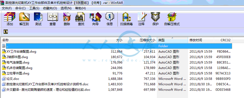
XY工作台装配图.dwg

Z轴部件图.dwg

外文翻译--激光切割陶瓷砖的速度:理论和经验值的比较.doc

数控激光切割机XY工作台部件及单片机控制设计说明书.doc

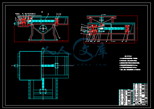
机床总装配图.dwg

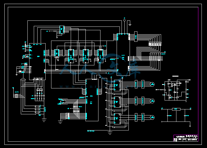
电气连接图.dwg

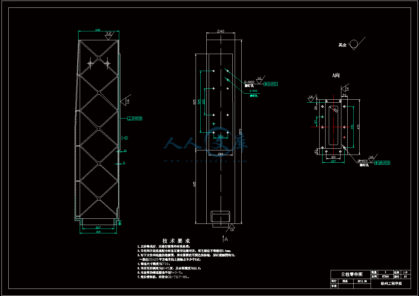
立柱零件图.dwg

论文.doc
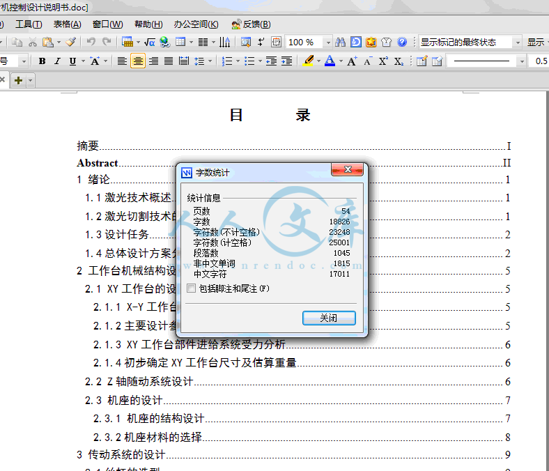
目录

摘要I

AbstractII

1 绪论1

1.1激光技术概述1

1.2激光切割技术的应用1

1.3设计任务2

1.4总体设计方案分析2

2 工作台机械结构设计5

2.1 XY工作台的设计5

2.1.1 X-Y工作台结构设计总述5

2.1.2主要设计参数及依据5

2.1.3 XY工作台部件进给系统受力分析6

2.1.4初步确定XY工作台尺寸及估算重量6

2.2 Z轴随动系统设计6

2.3 机座的设计7

2.3.1 机座的结构设计7

2.3.2机座材料的选择8

3 传动系统的设计9

3.1丝杠的选型9

3.1.1 丝杠的介绍9

3.1.2丝杠螺母副的选择10

3.1.3丝杠的校核11

3.2 滚珠丝杠支承的选择13

3.2.1 支承方式的选择13

3.2.2 轴承的选择13

3.3导轨的选型及计算13

3.3.1 导轨的组成种类及其应满足的要求13

3.3.2导轨材料的选择及热处理13

3.3.3导轨的选型及长度估算14

3.3.4导轨副的额定寿命计算15

3.3.5滚动导轨副的技术要求17

3.4 步进电机的选择17

3.4.1步进电机的特点17

3.4.2 步进电机的选型17

3.4.3步进电机惯性负载的确定19

3.4.4 步进电机接口及电路驱动20

3.5齿轮传动机构的确定23

3.5.1传动比的确定23

3.5.2齿轮结构主要参数的确定23

3.6传动系统刚度的确定24

4 消隙方法与预紧26

4.1 消隙方法26

4.2预紧27

5 控制系统设计29

5.1 确定机床控制系统方案29

5.2 主要硬件配置29

5.2.1主要芯片选择29

5.2.2 主要管脚功能29

5.2.3 EPROM的选用30

5.2.4 RAM的选用31

5.2.5 89C51存储器及I/O的扩展31

5.2.6 8155工作方式查询32

5.2.7状态查询33

5.2.8 8155定时功能33

5.2.9 芯片地址分配34

5.3 总体程序控制35

5.3.1流程图35

5.3.2主程序35

5.4 键盘设计36

5.4.1键盘定义及功能36

5.4.2 键盘程序设计37

5.5 显示器设计38

5.5.1显示器显示方式的选用38

5.5.2显示器接口38

5.5.3 8155扩展I/O端口的初始化38

5.6 插补说明39

5.7光电隔离电路41

5.8越界报警电路42

结论43

致谢44

参考文献45

附录46

主要设计参数及依据

本设计的XY工作台的参数定为:

   ①工作台行程:横向300mm,纵向400mm

   ②工作台最大尺寸(长×宽×高):900×900×500mm

   ③工作台最大承载重量:120Kg

   ④脉冲当量:0.001mm/pluse

   ⑤进给速度:XY轴均为0.05米/秒

   ⑥表面粗糙度:Ra0.8~1.6

   ⑦设计寿命:每天工作8小时,工作12.5年,250工作日/年

1 绪论

1.1激光技术概述

激光被誉为二十世纪最重大的科学发现之一,它刚一问世就引起了材料科学家的高度重视。1971年11月,美国通用汽车公司率先使用一台250W CO2激光器进行利用激光辐射提高材料耐磨性能的试验研究,并于1974年成功地完成了汽车转向器壳内表面(可锻铸铁材质)激光淬火工艺研究,淬硬部位的耐磨性能比未处理之前提高了10倍。这是激光表面改性技术的首次工业应用。多年以来,世界各国投入了大量资金和人力进行激光器、激光加工设备和激光加工对材料学的研究,促使激光加工得到了飞速发展,并获得了巨大的经济效益和社会效益。如今在中国,激光技术已在工业、农业、医学、军工以及人们的现代生活中得到广泛的应用,并且正逐步实现激光技术产业化,国家也将其列为“九五”攻关重点项目之一。“十五”的主要工作是促进激光加工产业的发展,保持激光器年产值20%的平均增长率,实现年产值200亿元以上;在工业生产应用中普及和推广加工技术,重点完成电子、汽车、钢铁、石油、造船、航空等传统工业应用激光技术进行改造的示范工程;为信息、材料、生物、能源、空间、海洋等六大高科技领域提供崭新的激光设备和仪器。

数控化和综合化把激光器与计算机数控技术、先进的光学系统以及高精度和自动化的工件定位相结合,形成研制和生产加工中心,已成为激光加工发展的一个重要趋势。

1.2激光切割技术的应用

激光切割是用聚焦镜将CO2激光束聚焦在材料表面使材料熔化,同时用与激光束同轴的压缩气体吹走被熔化的材料,并使激光束与材料沿一定轨迹作相对运动,从而形成一定形状的切缝。从二十世纪七十年代以来随着CO2激光器及数控技术的不断完善和发展,目前已成为工业上板材切割的一种先进的加工方法。在五、六十年代作为板材下料切割的主要方法中:对于中厚板采用氧乙炔火焰切割;对于薄板采用剪床下料,成形复杂零件大批量的采用冲压,单件的采用振动剪。七十年代后,为了改善和提高火焰切割的切口质量,又推广了氧乙烷精密火焰切割和等离子切割。为了减少大型冲压模具的制造周期,又发展了数控步冲与电加工技术。各种切割下料方法都有其有缺点,在工业生产中有一定的适用范围。

激光切割机是光、机、电一体化高度集成设备,科技含量高,与传统机加工相比,激光切割机的加工精度更高、柔性化好,有利于提高材料的利用率,降低产品成本,减轻工人负担,对制造业来说,可以说是一场技术革命。

激光切割的适用对象主要是难切割材料,如高强度、高韧性、高硬度、高脆性、磁性材料,以及精密细小和形状复杂的零件。激光切割技术、激光切割机床正在各行各业中得到广泛的应用。因此研究和设计数控激光切割有很强的现实意义。微机控制技术正在发挥出巨大的优越性。

内容简介:
徐州工程学院毕业设计外文翻译学生姓名学院名称机电工程学院专业名称机械设计制造及其自动化指导教师 原文:Laser cutting speeds for ceramic tile: a theoretical-empirical comparisonI. Black *Department of Mechanical and Chemical Engineering, Heriot-Watt University, Riccarton, Edinburgh EH14 4AS, UKReceived 21 October 1997; accepted 24 March 1998AbstractThis paper presents a comparison of theoretically-predicted optimum cutting speeds for decorative ceramic tile with experimentally-derived data. Four well-established theoretical analyses are considered and applied to the laser cutting of ceramic tile, i.e. Rosenthals moving point heat-source model and the heat balance approaches of Powell, Steen and Chryssolouris. The theoretical results are subsequently compared and contrasted with actual cutting data taken from an existing laser machining database. Empirical models developed by the author are described which have been successfully used to predict cutting speeds for various thicknesses of ceramic tile. # 1998 Elsevier Science Ltd. All rights reserved.Keywords: CO laser Ceramic materials Advanced cutting processes Laser modeling Cutting speeds1. List of symbolsA Absorptivitya Thermal di.usivity (m2/s)C Specific heat (J/kg K)d Cutting depth (mm)E Specific cutting energy (J/kg)k Thermal conductivity (W/m K)J Laser beam intensity (W/m2)L Latent heat of vaporisation (J/kg)l Length of cut (mm)n Coordinate normal to cutting frontP Laser power (W)P Laser power not interacting with the cutting front (W)Q Heat input (J/s)R Radial distance (mm)r Beam radius (mm)s Substrate thickness (mm)S Critical substrate thickness (mm)T Temperature ()T Ambient temperature ()T Peak temperature ()T Temperature at top surface ()t Time (s)V Cutting speed (mm/min)V Optimum cutting speed (mm/min)w Kerf width (mm)X, Y, Z Coordinate locationx, y, z Coordinate distance (mm) Conductive loss function Radiative loss function Convective loss function Angle between Z-coordinate and x-coordinate (rad)n Coordinate parallel to bottom surface Angle of inclination of control surface w.r.t. X-axis (rad)v Coupling coecient Translated coordinate distance (mm) Density (kg/m) Angle of inclination of control surface w.r.t. Y-axis (rad)2. IntroductionLaser cutting of a decorative ceramic tile has its own set of characteristic problems including burnout,striations, dross and out-of-flatness, which all affect the finish quality of a cut edge 1-3. A typical cut may have some or all of these features depending on the type of ceramic tile being processed and on the setting of the various set-up parameters. In a production environment, cutting speeds need to be optimised in order to reduce in-cut times without too much significant degradation of cut-edge quality. An optimum cutting speed can be defined as that which will produce full-through-cutting (FTC) with minimal micro-cracking both in the surface glaze and in the tile substrate.Therefore, it can be argued that the cutting speed necessary to raise approximately a cuboid of material of dimensions l, w and s to the materials melting or fusion temperature would be equal to the cutting speed that will just cut the material; higher cutting speeds will not allow FTC and on the other hand slower cutting speeds will result in the material absorbing more heat and reaching higher temperatures than is necessary to cut the tile. These higher temperatures will also result in greater thermal gradients and residual stresses, with the subsequent problems of micro-cracking in the surface glaze together with excess dross. Striation marks will also be exaggerated at slower cutting speeds and this will also reduce cut finish quality. It should also be noted that the various theoretical approaches outlined in this paper relate only to laser cutting in continuous wave (CW) mode.3.Theoretical approaches3.1. Calculating V using moving point heat-source Analysis At its simplest level, laser cutting can be considered to be a moving point heat-source problem where the point heat source is assumed to be the laser beam focused on the material to be cut moving at a constant cutting speed. Therefore, it is not unreasonable to utilise the heat-flow solutions determined by Rosenthal and as applied by Easterling 4. In this analysis it is assumed that the energy of the cutting source moves with constant speed along the X-axis of a fixed rectangular co-ordinate system as shown in Fig. 1. Ignoring radiative and convective heat transfer effects, the differential equation of heat flow expressed in the co-ordinates shown in Fig. 1 is given by Eq. (1).However, this equation essentially refers to a fixed coordinate system and may be modified to a moving coordinate system by replacing x with , where is the distance of the point heat source from some fixed position along the X-axis, which is dependent on the speed of the moving source as defined by = x - V.When differentiated with respect to , Eq. (1) yieldsand this equation can be simplified by assuming that a quasistationary temperature distribution exists. This means that the temperature distribution around a heat source of uniform velocity will settle down to a constant form, i.e. T/t= 0 provided q/V is constant. This is not an unreasonable assumption for the laser cutting of ceramic tile. Therefore Eq. (1) can be simplified to giveThis differential equation can now be solved for both thick and thin ceramic tile substrates, since in effect, the flow of heat is approximately two-dimensional for thin tiles and three-dimensional for thick ones. In the case of thin tiles, the heat transfer will be primarily by conduction, other effects being negligible. Eq. (4) gives the temperature-time distribution for three-dimensional heat flow (thick tiles) and Eq. (5) is the solution for two-dimensional heat flow (thin tiles), where The choice of either 2D or 3D heat flow is not only governed by tile thickness but also by material type. A critical thickness which defines the crossover, or boundary condition between the two can be derived by equating the thick and thin plate approaches and is given byThe relationship between S and V can be plotted graphically for the given laser cutting conditions, i.e. q3450 W (the maximum rated power of the laser cutter used), C800 J/kg K, r3380 kg/m3 (representative values for ceramic tile) and T=18 (ambient temperature) (Fig. 2).Fig. 2 is useful because if the range of cutting speeds for a given thickness of tile falls below the curve shown then the tile should be treated as a 2D (thin tile) case. However if a range of cutting speeds for a given tile lies in the regime above the curve then the 3D (thick tile) approach should be applied. It should be noted that for a tile whose range of cutting speeds straddles the curve on either side the thin tile case should only be considered.It is possible, by simplifying Eqs. (4) and (5), to eliminate the time variable to obtain Eq. (7) for the thick tile case and Eq. (8) for a thin tile case whereIn the thin case, the distance in the direction of the Z-axis can be ignored. Also by letting R= y, the temperature profile can be examined in the direction of the Y-axis. The following graphs were constructed using Eq. (8); Eq. (7) was not used as the tiles to be investigated straddled a range of cutting speeds. It should be noted that the cut zone referred to in Fig. 3 extends to an area corresponding to R = 0.5 mm (i.e. the beam radius).The curves in Fig. 3 show that by increasing V the peak temperature within the cut zone is reduced. They also show the optimum cutting speed that will cut the tiles, which occurs at the intersection with the line representing the representative melt temperature of ceramic tile, i.e. T=1327 (1600 K). Any cutting speed above this line should, in theory, produce FTC and any that fall below will not cut the tile. Note that thermal conductivity plays no part in Eqs. (7) and (8).In the calculation of V, Eqs. (7) and (8) are applied depending on whether the tile was considered to be thick or thin as defined by Eq. (6). To calculate V for a thin case, e.g. 3.7 mm, Eq. (8) can be arranged to giveletting q= P. The distance in the direction of the Z-axis is omitted from the expression for radial distance because the substrate thickness takes this parameter into consideration; therefore R = r. However, in the case of the thicker tile Eq. (7) can be arranged to givewhere R = (0.510)+ s. For both cases the peak temperature is set to equal the melt temperature of the tile.3.2. Calculating V using heat balance modelsPowell 5 presents an analysis in which, during laser cutting, a dynamic equilibrium exists in the cut zone that balances the incoming energy and material with the outgoing energy and material. Therefore a simple energy balance for laser cutting can be expressed as Energy supplied to cut zone= Energy used in generating a cut + Energy losses from the cut zone(by conduction, radiation, etc.)This can be expressed as the following formulaIf it is assumed that all of the laser power transmitted through the cut zone interacts with the cut front (P=0), that all laser power is absorbed by the tile substrate (A = 1) and that the conductive, radiative and convective losses are negligible, then the above equation reduces to where w= 2r. Since the cut zone for good quality CW cuts rarely exceeds a few microns the previous assumptions are not unreasonable. Noting that for full through cutting, V =l/t, rearranging the above formula gives Similarly, Steen 6 presents an analysis in which the cutting process can be approximately modelled by assuming all the energy enters the cut zone and is removed before significant conduction occurs (i.e. no significant energy loss). The outcome is a simple equation based on the heat balance for the material removed.If we assume that n31 when V = V, then Eq. (14) reduces towhich is the same as Eq. (13). This is to be expected since both Powell and Steen use basically the same energy balance approach.As an enhancement of the above, Chryssolouris presents a general model 7 based principally on a heat balance at the erosion front and a temperature calculation inside a material from heat conduction equations. In order to give a quantitative understanding of the effect of the different process parameters on the cutting process, an infinitesimal control surface on the erosion front surface is shown in Fig. 4.The control surface is inclined at an angle y with respect to the X-axis and at an angle with respect to the Y-axis, and is subjected to a laser beam of intensity J(x, y). The Cartesian co-ordinate system (x, y, z) is moving with the laser beam which has intensity profile J(x, y) projected onto the control surface. The heat balance at the control surface isIn order to derive simple analytical relations, simplifications need to be made. For instance, although heat is conducted three-dimensionally near the erosion front due to the presence of a bottom surface in cutting, which behaves as an adiabatic boundary, the heat conduction occurs two-dimensionally (downward conduction is negligible compared with conduction in other directions). Thus, in cutting it is assumed that heat is conducted two-dimensionally into the solid, so that the conduction term in Eq. (16) can be simplified aswhich gives the heat balance condition at the cutting front. The temperature gradient at the erosion front, assuming that the conduction area and direction do not change, can be determined by solving the following 1D heat conduction equationFrom Eq. (18) the temperature distribution inside the solid can be determined and differentiation of this gives the following temperature gradient at the erosion frontBy substituting the temperature gradient into the heat balance, an equation for the erosion front slope (i.e. tan ) in the cutting direction can be obtained. This slope is said to have an infinitesimal depth which forms an integral which, upon integration, gives an expression for the depth of cutBy setting d= s and the melt temperature at the top surface along the centre line of the cut, T1327, a value of V can be calculated for a specific type and thickness of tile, where (again) P450 W, r3380 kg/m, D = 2R = 1.010m,L856.410 J/kg ,C 800 J/kg K ,T =18and A = 1. Therefore, Eq. (20) can be arranged to givewhich, again, is similar to the formula derived from Steen and Powells analysis.4. Comparison with empirical modelsAn empirically-derived laser machining database for cutting ceramic tile has been compiled from extensive (and ongoing) experimental work in the Department of Mechanical and Chemical Engineering at Heriot-Watt University. The database contains specific information on cutting speeds associated with variation in such cutting parameters as shield gas type and pressure, nozzle size, focal point and, most importantly, surface finish quality. Table 1 below gives a comparison between V from this database with the previously described theoretical approaches. Note that, where available, a range of values is given from the database since ceramic tile is a non-homogeneous material and cutting conditions will vary markedly from one tile to another.Mean values of V were used to establish a best fit curve for the cutting data according to a method initially devised by Thomson 3, in which the empirical curve is plotted for the rated power of the laser cutter used and fitted to the following formulaewhere A, B, C and D are constants.This can be done in a variety of ways. The normal method to use is to take four points from the plotted graph and solve these simultaneously. The formula generated by fitting these coefficients back into Eq. (1) should then be checked to ensure that it follows the experimental curve and does not deviate beyond the upper and lower limits. If the first set of coefficients proves unsatisfactory, the process is repeated but different start points are chosen, or one or more of the coefficients A, C or D is set to zero. Cutting speeds at the machine limit should not be used when generating formulae for the curves, since the governing factor at these limits is no longer the process. For the given set of data for decorative ceramic tile, the following empirical equation was determinedwith C = D= 0.Livingstone and Black 1 developed an empirical equation describing the behaviour of V with s for the FTC of decorative ceramic tile which followed an exponential relationship of the formwhere and are constants determined by the least-squares method. For the data presented in Table 1, an equation of the formresulted. The theoretical results predicted in Table 1 are represented graphically in Fig. 5, together with the empirical curves derived from the database results.5. Concluding remarksFig. 5 shows that the predictive models describe a decrease in Vopt with an increase in tile thickness, V 1/s. This is what would be expected in practice. The differences between the individual theoretical predictions of V can be ascribed to the different analytical approaches taken in formulating a suitable cutting model. However, probably the most significant factor in the difference between predicted and experimental values of V is the variation in thermal and material properties between and throughout the different makes of ceramic tile. For instance, Spanish makes of tile are considerably denser and also able to retain more heat during cutting than the other types of tile considered 2.In addition to the vagaries of ceramic tile composition, the theoretical models utilised incorporate some or all of the following assumptions(1) A moving point source represents the laser beam.(2) The specific heat capacity is unaffected by changes in tile temperature or changes in state.(3) The latent heat of fusion due to phase transformations is neglected.(4) Effects of the shield gas are neglected.(5) All the heat input of the laser beam is absorbed in cutting.(6) The kerf is assumed to have simple 2D geometry with no slope on the cutting front (although Chryssolouris analysis does take this into account).(7) All of the laser power transmitted through the cut zone interacts with the cutting front.(8) There are negligible conductive, radiative and convective losses during cutting.(9) Powells analysis assumes that the cut zone has a high absorptivity due to its high temperature, the presence of absorptive oxides, the shallow angle of incidence to laser beam, its roughness and its absorptive layer of vapour.(10) Powells model assumes that the specific energy of cutting is taken to be constant.(11) Rosenthals model assumes a quasi-stationary temperature distribution.Additionally, the theoretical models presented also take no account of the finish or production method of the final cut. In practice, there may need to be as many as six V/s curves to account for every combination of cutting speed and cut quality for each of the following types of machine control:(i) Adaptive control, where problems associated with low V can be ignored because the adaptive control can compensate for this.(ii) Programmable control, where a curve should be produced for cutting intricate features, since this control system allows switching V and pulsing to compensate.(iii) No in-program control, where the curve must attempt to compromise between quality of cut and economy.In practice, empirical curves are produced for both quality and economy cutting. However, it is usually the case that many or all of these curves may be the same. Because of the limitations inherent in the theoretical analyses considered, it is the authors contention that, at present, modelling the behaviour of V with s using empirical techniques offers the most accurate way of determining V for decorative ceramic tile.AcknowledgementsThe author would like to express his thanks to the sta. of the Advanced Manufacturing Unit of the Department of Mechanical and Chemical Engineering, Heriot-Watt University for both their invaluable contribution to the work detailed in this paper and their permission to publish it.References1 Livingstone SAJ, Black I. Laser machining of ceramic tile.Lasers Eng 1996;5:127-48.2 Black I, Chua KL. CO laser cutting of thick ceramic tile. Opt Laser Technol 1997;29(4):193-205.3 Thomson GA. The development of a CO laser cutting material evaluation procedure and the construction of a database to store this information. Edinburgh: MPhil thesis, Heriot-Watt University, Jan. 1993.4 Easterling K. Introduction to the physical metallurgy of welding. 2nd ed. Butterworths, 1992, pp. 17-38.5 Powell J. CO laser cutting. Springer-Verlag, 1993, p. 206-208.6 Steen WM. Laser material processing. Springer-Verlag, 1991,pp. 75-76.7 Chryssolouris G. Laser Machining: Theory and Practice.Springer-Verlag, 1991, pp. 197-200.翻译:激光切割陶瓷砖的速度:理论和经验值的比较I.背景机械和化学工程系,赫瑞瓦特大学,卡顿,爱丁堡EH14广告商会,英国1997年10月21日收稿,1998年3月24日接受摘要本文提出了理论上预测的最佳装饰陶瓷砖切割速度和实验派生数据的比较。 考虑了四种完善的理论分析并应用到激光切割瓷砖,即罗森塔尔的移动点热源模型和鲍威尔,施特恩和Chryssolouris的热平衡方法。理论分析的结果与随后的从现有的激光切割加工数据采取的实际数据对比。由作者开发的经验模型的描述已被成功地用于预测瓷砖切割不同厚度的速度。 1998 Elsevier科学有限公司保留所有权利。关键词:CO2激光,陶瓷材料,先进的切割工艺,激光造型;切割速度1.符号列表A 吸收率a 热扩散 (m/s)C 比热 (J/kg K)d 切割深度 (mm)E 具体切割能源 (J/kg)k 热导率 (W/m K)J 激光束的强度 (W/m)L 蒸发潜热 (J/kg)l 切割长度 (mm)n 正常的切割前协调P 激光功率 (W)P 切割前不互动的激光功率(W)q 热输入 (J/s)R 径向距离 (mm)r 光斑半径 (mm)s 基板厚度 (mm)S 关键基板厚度 (mm)T 温度 ()T 环境温度 ()T 峰值温度 ()T 顶面的温度 ()t 时间(s)V 切割速度 (mm/min)V 最佳切割速度 (mm/min)w 切缝宽度 (mm)X, Y, Z 坐标位置x, y, z 坐标距离 (mm) 导电损失函数 辐射损失函数 对流损失函数 Z坐标和x坐标夹角 (rad) 平行于底面坐标 控制面相对于X轴的倾斜角度 (rad) 耦合系数 坐标转化距离 (mm) 密度 (kg/m) 控制面相对于Y轴的倾斜角度 (rad)2. 简介瓷砖装饰的激光切割有其特征问题,包括疲劳,裂纹,碎屑和外平坦度,这些都影响了一条切割边缘的最终质量1-3。一个典型的切割会根据正在处理中的瓷砖的一些或全部特点在各个设置进行参数设置。在生产环境中,切割速度需要优化以在没有太多切割边缘的质量的明显退化下减少必要切割时间。最佳切割速度可以定义为使生产的整个切割过程无论是在瓷砖表面还是底层都产生最少的微裂纹。因此,可以认为必须的切割速度仅仅切割了材料以加工成一件尺寸为l,w,s的长方体材料而不使其温度到达它的融化温度;更高的切割速度不利于一次切割,而切割速度慢会导致吸收更多的热量而使材料温度高于切割陶瓷所必须的温度。这更高的温度也将导致更大的温度梯度和残余应力,以及微裂纹釉的表面和过剩残余的后续问题。切割速度较慢时裂纹也将变大,这也将减小切割加工质量。还应该指出,在这个文件中提出的各种理论方法只涉及到激光连续波(CW)模式切割。3. 理论方法3.1利用移动点热源分析计算 V在最简单的层次,激光切割可以被认为是一个移动的点热源问题,即点热源被假定为激光束聚焦到的材料在不断被切割,且随着切割速度移动。因此,它并非不合理地利用由罗森塔尔提出和经伊斯特林应用的热流解决方案4。在这种分析中,假定的是,切削源以恒定速度沿固定矩形坐标系X轴移动的能量,如图 1 所示。图1. 以点热源和恒定V方式的切割配置忽略辐射和对流热交换的影响,坐标显示图 1 所示的热流量微分方程由式(1)给出。然而,这个公式基本上是指一个固定的坐标系,并可能通过以替换x使其修改成一个移动坐标系,其中是从热源点到一些固定位置沿X轴的距离,这取决于由=x - V定义的移动源的速度。关于和式(1)的产量的差异,这个公式可以通过假设存在一个准稳态温度分布而简化。这意味着,围绕着匀速热源的温度分布将为一固定的形式,即 q/V 值恒定的情况下 T/t = 0 。这并非激光切割瓷砖的不合理的假设。因此,式(1)可以简化地给出这个微分方程,现在可以解决厚,薄底层的瓷砖的问题,由于实际上,热流量对于薄砖是二维的,对于厚砖是三维的。在薄砖的情况下,热传递将以传导为主,其他效果是微不足道的。式(4)给出了三位热流(厚砖)的温度时间分布,式(5)是二维热流(薄砖)的解决方案,其中 在选择二维或三维热流时不仅要看瓷砖的厚度,而且按材料类型。定义两者之间的交叉或边界条件的临界厚度是使厚,薄板材的值接近等同的厚度,它由(6)给出。S和V的关系可以根据给定的激光切割条件生动地划分出来,即 q450 W(最大的激光切割机使用的额定功率),C800 J/kg K ,3380 kg/m (瓷砖代表值),T=18 (周边温度)(图2)。图2. S和V的关系图图2是有用的,因为如果给定厚度的瓷砖的切割速度范围低于所示曲线,那么瓷砖应被视为一个二维(薄砖)的情况下处理。但是如果一个给定的瓷砖切割速度范围在于在曲线上面,那么应该用三维(厚砖)的方法。应当指出,对于一个切割速度范围横跨曲线的瓷砖,不论更倾向于哪边只作薄砖的情况处理。通过简化方程(4)及(5)消除时间变量可能得到应用于厚瓷砖情况的式(7)和应用于薄砖情况的式(8)。在薄的情况下,在Z轴方向的距离可以忽略不计。同时通过让R = y,则可以在Y轴方向检查温度曲线。下图为使用式(8)而构建;情商。式(7)不研究跨越切削速度范围的瓷砖。应该指出的是,图3中提到的削减区域延伸到相应的区域为R= 0.5毫米(即光束半径)。图3. 3.7mm到8.6mm厚瓷砖切割区T和V的关系图图3的曲线可以看出通过增大V,切割区域内的峰值温度降低。图上还表明了切削瓷砖的最佳切割速度,这将发生在与代表瓷砖融化的温度线的交叉处,即 T=1327 (1600 K)。任何高于这条曲线的速度在理论上应能实现一次切割,而其它低于这条曲线的速度将不能用于切割瓷砖。请注意,热导率不会参与方程(7)及(8)。在计算 V 时,式(7)和式(8)是否适用取决于瓷砖是否是由式(6)中定义的厚和薄来考虑的。要计算一个薄的情况下的 V ,可以让 q = P 通过式(8)给出。Z轴方向的距离是省略表达的径向距离,因为考虑到底层厚度这个参数;所以 R = r 。然而,在较厚的瓷砖情况下,可以通过定义 R = (0.510)+ s ,以式(7)给出V 的值。对于这两种情况,最高温度设定为等于瓷砖融化温度。3.2 使用热平衡模型计算 V 鲍威尔5提出了一种分析方法:在激光切割的过程中,在切削区域存在一个动态的平衡,即加入的能量及材料和离开的能量及材料的平衡。因此一个简单的激光切割能量平衡可以表示为供应削减区域的能量=完成切割动作所需的能量+从切削区域损失的能量(通过传导,辐射等)。这可以表示为下列公式如果假定,所有的激光功率传输通过切削区域并与切割前有所交互(P=0),所有的激光功率都被瓷砖底层所吸收(A = 1),而导电,辐射和对流损失可以忽略不计,则当 w = 2r 时,上述公式简化为由于连续优质切削的区域很少超过几微米,故以前的假设并非不合理。注意到对于一次切割,V = l / t ,重新整理上述公式,得同样,施特恩6提出了一种分析方法:切割过程可以近似地模拟通过假设所有的能量进入切割区并在重要的传导发生之前被转移(即没有显著的能量损失)。其结果是一个用于去除材料的以热平衡为基础的简单方程。如果我们假设,当 v1,V = V ,则方程(14)简化为式(13)的情况与之等同。这是意料之中的,因为鲍威尔和施特恩基本上都使用了相同的能量平衡方法。作为上述的说明,Chryssolouris提出了一个通用模型,其主要以在侵蚀前线的热平衡和内部材料的通过热传导方程的温度计算为基础7。为了对切削过程中的不同工艺参数的影响有一个定量认识,前侵蚀表面上的一个无穷小的控制面如图4所示。图4. 切割前区的控制面控制面是倾斜了一个关于x轴的夹角和在一个关于Y轴夹角,并遭受了强度J(x,y)的激光束
温馨提示:
1: 本站所有资源如无特殊说明,都需要本地电脑安装OFFICE2007和PDF阅读器。图纸软件为CAD,CAXA,PROE,UG,SolidWorks等.压缩文件请下载最新的WinRAR软件解压。
2: 本站的文档不包含任何第三方提供的附件图纸等,如果需要附件,请联系上传者。文件的所有权益归上传用户所有。
3.本站RAR压缩包中若带图纸,网页内容里面会有图纸预览,若没有图纸预览就没有图纸。
4. 未经权益所有人同意不得将文件中的内容挪作商业或盈利用途。
5. 人人文库网仅提供信息存储空间,仅对用户上传内容的表现方式做保护处理,对用户上传分享的文档内容本身不做任何修改或编辑,并不能对任何下载内容负责。
6. 下载文件中如有侵权或不适当内容,请与我们联系,我们立即纠正。
7. 本站不保证下载资源的准确性、安全性和完整性, 同时也不承担用户因使用这些下载资源对自己和他人造成任何形式的伤害或损失。
提示  人人文库网所有资源均是用户自行上传分享,仅供网友学习交流,未经上传用户书面授权,请勿作他用。
关于本文
本文标题:数控激光切割机XY工作台部件及单片机控制设计【5张图纸】【优秀】
链接地址:https://www.renrendoc.com/p-423437.html

官方联系方式

2:不支持迅雷下载,请使用浏览器下载   
3:不支持QQ浏览器下载,请用其他浏览器   
4:下载后的文档和图纸-无水印   
5:文档经过压缩,下载后原文更清晰   
关于我们 - 网站声明 - 网站地图 - 资源地图 - 友情链接 - 网站客服 - 联系我们

网站客服QQ:2881952447     

copyright@ 2020-2025  renrendoc.com 人人文库版权所有   联系电话:400-852-1180

备案号:蜀ICP备2022000484号-2       经营许可证: 川B2-20220663       公网安备川公网安备: 51019002004831号

本站为文档C2C交易模式,即用户上传的文档直接被用户下载,本站只是中间服务平台,本站所有文档下载所得的收益归上传人(含作者)所有。人人文库网仅提供信息存储空间,仅对用户上传内容的表现方式做保护处理,对上载内容本身不做任何修改或编辑。若文档所含内容侵犯了您的版权或隐私,请立即通知人人文库网,我们立即给予删除!