外文翻译--摩擦片式离合器简介.doc

商务车拉式离合器的设计【汽车类】【3张CAD图纸+毕业论文】

收藏

压缩包内文档预览:
预览图 预览图 预览图 预览图 预览图 预览图 预览图 预览图 预览图 预览图 预览图 预览图 预览图 预览图 预览图 预览图 预览图
编号:427115    类型:共享资源    大小:1.34MB    格式:RAR    上传时间:2015-04-23 上传人:上*** IP属地:江苏
39
积分
关 键 词:
商务车 离合器 设计 汽车 cad图纸 毕业论文 拉式离合器 商务车拉式离合器
资源描述:

商务车拉式离合器的设计

47页 14000字数+说明书+外文翻译+3张CAD图纸【详情如下】

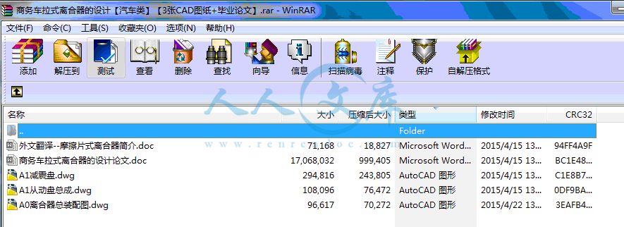
A0离合器总装配图.dwg

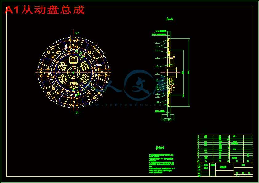
A1从动盘总成.dwg

A1减震盘.dwg

商务车拉式离合器的设计论文.doc

外文翻译--摩擦片式离合器简介.doc

摘要

本次设计题目是FORLAND轻型汽车离合器设计(拉式)

离合器是汽车传动系的重要组成部分,它设计的成功与否,将直接影响到整车性能的好坏。

由本车的发动机扭矩较小,故设计中采用单片膜片弹簧离合器,并采用带扭矩减震器的从动盘。为了使离合器接合平顺,以保证汽车的平稳起步,采用了有轴向弹性的从动片。

本文内容包括:轻型汽车的离合器结构方案论证;离合器工作特性(扭矩传递特性);离合器的基本结构参数设计与选型;强度校核;工艺过程制定和尺寸链计算。

关键词:从动盘  压缩弹簧  制造材料

Abstract

The topic of this sign is design a clutch for FORLAND commercial vehicle(pull_type).

It is the most important part of the light vehicle’s transform-system. The performance of light vehicle is largely relative to the quality of the design.

According to the torque, a single dry-disc diaphragm-spring clutch is used, and a clutch disc with a torsional absorber is fixed. To start the vehicle stability, the clutch must be engaged smoothly, so a plate segment with a axisal elasticity is mounted.

In the paper, I introduced the selection of the possible type of the clutch(torque operation characteristic). The selection of the found a mental parameter and the determination of the main dismensious the structure design of the components and corresponding calculation.

Key words: driven disk compression spring material

目录

绪论1

第一章   结构方案设计2

1.1 总论2

1.2   总成零件结构方案分析4

1.2.1   从动盘数目分析4

1.2.2   压紧弹簧的选择4

1.2.3   从动盘结构方案分析7

1.2.4  从动盘摩擦片结构方案分析9

1.2.5  其他零部件结构方案分析10

第二章   整体性能参数选择与计算12

2.1 摩擦片尺寸计算12

2.2 后备系数的确定13

2.2.1后备系数选择13

2.2.2 性能参数计算14

2.3  第一轴和从动盘毂花键尺寸选取和校验15

2.3.1 花键尺寸d计算15

第三章   膜片弹簧设计17

3.1 拉式膜片弹簧的工作原理17

3.2  拉式膜片弹簧的载荷——变形特性17

3.2.1 接合位置的载荷变形公式18

3.2.2 分离时的载荷变形公式19

3.2.3  小端载荷——变形特性21

3.3    拉式膜片弹簧应力变形特性21

3.3.1  碟形弹簧部分的应力——变形公式21

3.3.2  碟形部分子午剖面上切向应力分布:22

3.3.3  拉式膜片弹簧的应力计算23

3.4  拉式膜片弹簧的设计24

第四章    离合器扭转减震器基本参数选择27

4.1 概述27

4.2 主要性能参数计算和分析27

4.2.1减震器的极限转矩27

4.2.2  计算减震器阻尼力矩28

4.2.3 计算减震器的预紧扭转力矩29

4.2.4 减震弹簧位置半径的确定29

4.2.5 由参考文献提供的列表29

第五章  其余结构参数校核32

5.1 传力片强度校核32

5.2 压盘热容量校核32

第六章 主要零件加工工艺34

6.1 主要零件加工工艺34

6.1.1膜片弹簧的制造工艺34

6.2 工艺尺寸链的计算37

结束语40

致谢41

参考文献42

绪论

我国正处于社会主意初级阶段,主要的工作重点是发展社会生产力,为适应上层建筑的需要,为了使生产关系适应生产力,还要不断的推动科学技术的发展。

现代汽车已成为各国国民经济中不可或缺的一部分,而离合器作为组成汽车的一部分,对其的需求也是愈来愈高。

离合器作为机械传动系的重要组成部分,位于传动系的首端,用于切断和传递传动动力。故汽车离合器设计的好坏,直接关系到汽车是否能够平稳起步;能否可靠的在换挡时将发动机与传动系分离,从而减少变速器中齿轮的冲击,便于换挡;是否能在工作中受到较大载荷时,以打滑的方式保护发动机和传动系不至于过载而损坏。

由于城市道路普遍较窄的现状,车流量的不断增加,导致道路交通情况的日趋复杂,司机在行驶中需要不断的换挡,停车,起步,造成离合器使用频率增高,使用条件日趋严酷,因此设计上应保证离合器有优良的工作性能,即保证其上限工作极限。离合器工作时,温度上升,导致摩擦系数变换,压紧力变化。当散热等系能指标满足时,同时要考虑到国内目前的生产工艺水平,以降低成本和维修费用等。第一章   结构方案设计

1.1 总论

首先应该深入研究对汽车离合器的设计要求,根据离合器在汽车中所处的位置,保证离合器的良好工作性能。一部合格的离合器至少需要满足以下要求:

1.在任何行驶条件下,既能可靠的传递发动机的最大转矩,并有适当的转矩储备,又能防止传动系过载。

2.接合时要完全、平顺、柔和,保证汽车起步时没有抖动和冲击。

3.分离时要迅速、彻底。

4.从动部分转动惯量要小,以减轻换挡时变速器齿轮间的冲击便于换挡和减小同步器的磨损。

5.应有足够的吸热能力和良好的通风散热效果,以保证工作温度不致过高,延长时其使用寿命。

6.应能避免和传动器的扭转振动,缓和冲击和降低噪声的能力。

7.操纵轻便,准确,以减轻驾驶员的疲劳。

8.作用在从动盘上的总压力和摩擦材料的摩擦因数在离合器工作过程中变化要尽可能小,以保证有稳定的工作性能。

9.具有足够的强度和良好的动平衡,以保证其工作可靠、使用寿命长。

10.结构应简单、紧凑、质量小,制造工艺性好,拆装,维修,调整方便等。

离合器的主要功用是切断和实现发动机对传动系的动力传递,保证汽车起步时将发动机和传动系平顺的接合,确保汽车平稳起步;在换挡时将发动机与传动系分离,减少变速器中换挡齿轮之间的冲击;在工作中受到较大的动载荷时,能限制传动系所承受的最大转矩,以传动系各零部件因过载而损坏;有效的降低传动系中的振动和噪声等。

基于以上考虑,下面将选择本设计离合器的传递动力方式。

用于离合器传递动力的方式有摩擦、液力、磁力等几种方式。液力、磁力离合器具有自动适应负载变化,自动变扭等几种优良性能,但其缺点是结构过于复杂,价格较高,体积较大,重量大,维修困难等。鉴于以上几种优点,目前绝大多数汽车上仍使用摩擦式离合器,只有为数不多的高档轿车,及一些工作负荷较大,且工作条件恶劣的重型车,矿山车上使用液力离合器。本设计是轻型汽车,工作条件较好,负荷也较小,采用液力或磁力离合器大可不必。因此,本设计采用摩擦式离合器。

离合器主要由主动部分,从动部分,压紧机构和操纵机构组成。

1、主动部分

?主动部分包括飞轮、离合器盖、压盘等机件组成。这部分与发动机曲轴连在一起。离合器盖与飞轮靠螺栓连接,压盘与离合器盖之间是靠3-4个传动片传递转矩的。

2、从动部分

?从动部分是由单片、双片或多片从动盘所组成,它将主动部分通过摩擦传来的动力传给变速器的输入轴。从动盘由从动盘本体,摩擦片和从动盘毂三个基本部分组成。为了避免转动方向的共振,缓和传动系受到的冲击载荷,大多数汽车都在离合器的从动盘上附装有扭转减震器。

?为了使汽车能平稳起步,离合器应能柔和接合,这就需要从动盘在轴向具有一定弹性。为此,往往在动盘本体园周部分,沿径向和周向切槽。再将分割形成的扇形部分沿周向翘曲成波浪形,两侧的两片摩擦片分别与其对应的凸起部分相铆接,这样从动盘被压缩时,压紧力随翘曲的扇形部分被压平而逐渐增大,从而达到接合柔和的效果。

3、扭转减振器

?离合器接合时,发动机发出的转矩经飞轮和压盘传给了动盘两侧的摩擦片,带动从动盘本体和与从动盘本体铆接在一起的减振器盘转动

?动盘本体和减振器盘又通过六个减振器弹簧把转矩传给了从动盘毂。因为有弹性环节的作用,所以传动系受的转动冲击可以在此得到缓和。传动系中的扭转振动会使从动盘毂相对于动盘本体和减振器盘来回转动,夹在它们之间的阻尼片靠摩擦消耗扭转振动的能量,将扭转振动

参考文献

[1]于骏一,邹青.机械制造技术基础(第一版)[M]. 北京:机械工业出版社,2004年.

[2]濮良贵,纪名刚.机械设计(第八版)[M].北京:高等教育出版社,2006年.

[3]成大先.机械设计手册(第三版)[M].北京:化学工业出版社,1999年.

[4]徐石安,江发潮.汽车离合器/汽车设计丛书[M].北京:清华大学出版社,2005年.

[5]钱大川.新型联轴器、离合器选型设计与制造工艺实用手册[M].北京:北京工业大学出版社,2006年.

[6] 甘永力.精度设计基础[M].长春:吉林人民出版社,2005.

[7] 何少平.机械结构工艺性[M].长沙:中南大学出版社,2003.

[8] 机械结构工艺性[M].北京:机械工业出版社,1997.

[9] 工业机械手设计基础[M].天津:天津科学技术出版社,1979.

[10] 工业机械手图册[M].北京:机械工业出版社,1978.

[11] 沈世德.机械原理[M].北京:机械工业出版社,2002.

[12] MARGHITU, D. B.  Mechanical Engineer's Handbook[M]   2001.

[13] MERCER, R. B.  Industrial Control Wiring Guide[M].2001.

[14] POPE, J.E.Rules of Thumb for Mechanical Engineers[M]. 1996.

[15]REIMPELL,J.CombinationMachine-EngineeringPrinciples[M].2001.

[16] Ii Z.X.,Qin Z.,Jiang S.et a1.Coordinated motion generation

and real-time grasping force control for multi-fingered manipulation. Proceedings of the IEEE Internationa1 Conference on Robotics and Automation[M].1998.

[17] TANAKA, K.  The Science and Technology of CNC[M]. 1999.

内容简介:
摩擦片式离合器简介离合器是汽车的重要组成部分,是汽车传动部分核心部件,它的性能指标的好坏直接关系到汽车整体的质量,因而对其性能的测定有着十分重要的意义。本文介绍了摩擦盘式离合器的主要结构和工作原理,概述了摩擦盘离合器实验台的作用、基本组成和工作原理;进行了摩擦盘离合器实验台的方案和结构设计,主要包括离合器组件的选择、实验台架设计、零部件的布置、动力选择、传感器的选择和有关参数测量与计算。一、汽车离合器的作用离合器位于发动机和变速箱之间的飞轮壳内,用螺钉将离合器总成固定在飞轮的后平面上,离合器的输出轴就是变速箱的输入轴。驾驶员行驶过程中可根据需要踩下或松开离合器踏板,使发动机与变速箱暂时分离和逐渐接合,以切断或传递发动机向变速器输入的动力。1、保证汽车平稳起步起步前汽车处于静止状态,如果发动机与变速箱是刚性连接的,一旦挂上档,汽车将由于突然接上动力突然前冲,不但会造成机件的损伤,而且驱动力也不足以克服汽车前冲产生的巨大惯性力,使发动机转速急剧下降而熄火。如果在起步时利用离合器暂时将发动机和变速箱分离,然后离合器逐渐接合,由于离合器的主动部分与从动部分之间存在着滑磨的现象,可以使离合器传出的扭矩由零逐渐增大,而汽车的驱动力也逐渐增大,从而让汽车平稳地起步。2、便于换档汽车行驶过程中,经常换用不同的变速箱档位,以适应不断变化的行驶条件。如果没有离合器将发动机与变速箱暂时分离,那么变速箱中啮合的传力齿轮会因载荷没有卸除,其啮合齿面间的压力很大而难于分开。另一对待啮合齿轮会因二者圆周速度不等而难于啮合。即使强行进入啮合也会产生很大的齿端冲击,容易损坏机件。利用离合器使发动机和变速箱暂时分离后进行换档,则原来啮合的一对齿轮因载荷卸除,啮合面间的压力大大减小,就容易分开。而待啮合的另一对齿轮,由于主动齿轮与发动机分开后转动惯量很小,采用合适的换档动作就能使待啮合的齿轮圆周速度相等或接近相等,从而避免或减轻齿轮间的冲击。3、防止传动系过载汽车紧急制动时,车轮突然急剧降速,而与发动机相连的传动系由于旋转的惯性,仍保持原有转速,这往往会在传动系统中产生远大于发动机转矩的惯性矩,使传动系的零件容易损坏。由于离合器是靠磨擦力来传递转矩的,所以当传动系内载荷超过磨擦力所能传递的转矩时,离合器的主、从动部分就会自动打滑,因而起到了防止传动系过载的作用。二、摩擦片式离合器1、离合器的功用与要求:(1)功用1)使发动机与传动系逐渐接合,保证汽车平稳起步。2)暂时切断发动机与传动系的联系,便于发动机的起动和变速器的换档,保证传动系换档时工作平顺。3)限制所传递转矩,防止传动系过载(2)对离合器的要求:1)具有合适的储备能力。既能保证传递发动机最大扭矩,又能防止传动系过载。2)接合平顺柔和,以保证汽车平稳起步3)分离迅速彻底,便于换档和发动机起动。4)具有良好的散热能力。5)操纵轻便,以减轻驾驶员的疲劳。6)从动部分的转动惯量应尽量小,以减小换档时的冲击。2、摩擦片式离合器工作原理(1)离合器的组成主动部分、从动部分、压紧装置、分离机构和操纵机构 (2)离合器的工作原理(视频)1)接合状态:弹簧将压盘、飞轮及从动盘互相压紧,发动机的转矩经飞轮及压盘通过摩擦面的摩擦力矩传至从动盘。2)分离过程:踩下踏板,套在从动盘毂滑槽中的拨叉,便推动从动盘克服压紧弹簧的压力右移而与飞轮分离,摩擦力消失,从而中断了动力传动。3)接合过程:缓慢地抬起离合器踏板,使从动盘在压紧弹簧压力作用下左移与飞轮恢复接触,二者接触面间的压力逐渐增加,相应的摩擦力矩逐渐增加,离合器从完全打滑、部分打滑,直至完全接合。3、摩擦离合器主要类型1)按从动盘数目分为:单片式、双片式、多片式。 轿车和轻中型货车一般采用单片式2)按压紧弹簧的型式与布置分:周布弹簧式、中央弹簧式、膜片弹簧式3、摩擦片式离合器的构造(一)摩擦片式离合器的基本构造 摩擦片式离合器一般由主动部分、从动部分、压紧机构和操纵机构四部分组成。 1、主动部分 主动部分包括飞轮、离合器盖、压盘等机件组成。这部分与发动机曲轴连在一起。离合器盖与飞轮靠螺栓连接,压盘与离合器盖之间是靠34个传动片传递转矩的。2、从动部分 从动部分是由单片、双片或多片从动盘所组成,它将主动部分通过摩擦传来的动力传给变速器的输入轴。从动盘由从动盘本体,摩擦片和从动盘毂三个基本部分组成。为了避免转动方向的共振,缓和传动系受到的冲击载荷,大多数汽车都在离合器的从动盘上附装有扭转减震器。 为了使汽车能平稳起步,离合器应能柔和接合,这就需要从动盘在轴向具有一定弹性。为此,往往在动盘本体园周部分,沿径向和周向切槽。再将分割形成的扇形部分沿周向翘曲成波浪形,两侧的两片摩擦片分别与其对应的凸起部分相铆接,这样从动盘被压缩时,压紧力随翘曲的扇形部分被压平而逐渐增大,从而达到接合柔和的效果。 3、扭转减振器 离合器接合时,发动机发出的转矩经飞轮和压盘传给了动盘两侧的摩擦片,带动从动盘本体和与从动盘本体铆接在一起的减振器盘转动动盘本体和减振器盘又通过六个减振器弹簧把转矩传给了从动盘毂。因为有弹性环节的作用,所以传动系受的转动冲击可以在此得到缓和。传动系中的扭转振动会使从动盘毂相对于动盘本体和减振器盘来回转动,夹在它们之间的阻尼片靠摩擦消耗扭转振动的能量,将扭转振动衰减下来。 4、压紧机构 压紧机构主要由螺旋弹簧或膜片弹簧组成,与主动部分一起旋转,它以离合器盖为依托,将压盘压向飞轮,从而将处于飞轮和盘压间的从动盘压紧。 螺旋弹簧分沿周向布置和在中央布置两种。将一个圆柱形或圆锥形弹簧布置在中央的离合器称为中央弹簧离合器。 (二)两种典型的摩擦片式离合器1、膜片弹簧离合器(1)结构1)膜片弹簧:用优质弹簧钢板制成,形状为碟形,开有径向切槽,切槽内端连通,外端为圆孔。两个切槽之间钢板形成一个弹性杠杆,即是压紧弹簧又是分离杠杆2)压紧装置:压紧装置由压盘、离合器盖、膜片弹簧、支承圈、定位铆钉、分离钩、传动片组成(2)工作原理(视频):膜片弹簧中部两侧由支承圈夹持在离合器盖上,支承圈既是变形支点,压盘周边有多个分离钩与膜片弹簧钩在一起。 (3)膜片弹簧的弹性特性及其特点 :1)根据对膜片弹簧与螺旋弹簧特性曲线的对比,膜片弹簧分离时的压力小于接合时的压力2)当摩擦片变薄,螺旋弹簧弹性下降,而膜片弹簧弹力几乎不变,膜片弹簧具有自动调节压紧力的特点膜片弹簧的弹性压力几乎与转速无关,具有高速时压紧力稳定的特点3)综上所述,膜片弹簧离合器结构简单、轴向尺寸小、良好的弹性性能、能自动调节压紧力、操纵轻便、高速时压紧力稳定、分离杠杆平整不需调整等特点。在中、小型汽车上广泛应用2、周布弹簧式离合器:主、从动部分、压紧部分均安装在离合器壳内、外及驾驶室中(1)主动部分 :1)发动机飞轮和压盘是离合器的主动部分,离合器盖通过定位销安装在飞轮上,保证同心,盖侧面有散热通风口,压盘的平面和飞轮的平面组成主动件的摩擦面,压盘与离合器盖通过传动片来传递扭矩。2)特点:没有传动间隙,没有驱动部位磨损问题,维修量小,传动效率高,无冲击噪声及压盘定心性问题3)缺点:传动片反向承载能力差,汽车反拖时易折(2)从动部分(含扭转减震器) :1)主要部件是从动盘(含扭转减振器),由两片摩擦衬片、从动钢片、从动盘毂组成,从动盘钢片用薄弹簧钢片制成,与从动盘毂铆在一起上边有辐射状槽,防止热变形。衬片应具有较大的摩擦系数,从动盘钢片具有轴向弹性,可使离合器接合柔和,起动平稳,连接方式:钢片与前衬片铆在一起,弹簧片与后衬片铆在一起,最后盘片与弹簧片铆在一起2)特点:这种结构使后衬片与钢片在从动盘自由状态时有一定间隙,在结合时弹性变形使压紧力逐渐增加产生轴向弹性,接合柔和(3)压紧机构:沿压盘圆周对称布置的16个弹簧 (4)分离机构:由分离叉和分离杠杆组成根据摩擦片数分:单片离合器:特点:结构简单,分离彻底,尺寸紧凑,从动部分惯量小,散热性好,调整方便。双片离合器:特点:传递转矩的能力较强,接合较平顺,但分离不够彻底,中间压盘散热不良。5、机构:踏板、连杆、分离叉、分离套筒、分离杠杆摩擦式离合器的自由行程:即分离轴承与分离杠杆之间的间隙,是以调整三个螺母的松紧实现的;这样离合器它要充气接合与彻底分离相矛盾;自由行程调得过大,离合器分离不彻底,引起挂挡困难;自由行程调得太小,离合器不能充分接合而引起打滑。它提供了一种方便地调整离合器自由行程的分离套筒,有效地解决了离合器彻底分离与充分接合这一对矛盾。它是这样实现的:将分离套筒稍为加长,与分离轴承的连接方式改为纹连接,分离轴承自身带调整节螺母,在分离轴承与分离套筒下带螺纹之间有锁紧螺母,即将分离轴承调好定位后,再用锁紧螺母紧固。6、离合器结构上的特殊问题1分离杠杆的运动干涉:为避免运动干涉,在分离杠杆的支点采用浮动销支点。2离轴承的自由行程:分离杠杆内端与分离轴承内端应留一定量的间隙。 =34mm3板自由行程:司机踩下踏板后,先要消除间隙,然后才开始分离离合器。 L=3545mm4踏板自由行程的调整:拧动分离拉杆上的螺母,以调整拉杆的有效长度, 从而调整。5分离杠杆的调平:把分离杠杆调至与飞轮端面平行的同一平面, 保证离合器分离彻底。 摩擦片:(T过高发生拱曲变形)在径向开有切口,并在离合器盖上冲压有窗孔进行通风散热。 压紧弹簧:(T过高弹簧老化弹力下降) a:压盘上装弹簧处做成凸起的肋条,以减少压盘对弹簧传热。 b:在压盘与弹簧间装有隔热垫片7、合器操纵机构1、功用:使离合器分离,而后接合。2分类: 2、1、人力式操纵机构 :2、1、1、操纵机构:a、绳索传动装置:主要使用于发动机后置,离合器远离驾驶室。优:造价低,布置方便。缺:绳索寿命短,拉伸刚度小,仅用于轻、微型车、客车。 b、杆系传动装置:用于大多数汽车。 优:结构简单,工作可靠,广泛采用。 缺:杆件间铰接较多,摩擦损失大,费力。液压式操纵机构:组成:主缸、工作缸、管路系统。优点:靠液体压力传递踏板力,摩擦阻力小,重量轻,布置方便。液体有缓冲作用,即使“急放”踏板,离合器也能接合柔和,舒适性好。轿车上应用较多。缺点:结构复杂、制造工艺要求高。3、气压助力式:原理及组成:空气压缩机、储气罐、控制阀、助力气缸。缺点:结构复杂、质量大、较少采用。主要应用于一些重型车上。 8、摩擦式的磨损及影响因素磨损是经济型汽车干摩擦离合器损坏的主要原因。通过分析经济型汽车干摩擦式离合器在滑动摩擦条件下磨损的基本类型及其影响因素,得出磨粒磨损、粘着磨损和疲劳磨损是其磨损的基本类型,摩擦材料、温度和滑动速度是磨损的主要影响因素:通过分析经济型汽车干摩擦离合器磨损过程三个阶段的磨损类型和磨损量,得出缩短磨合磨损阶段、延长稳定磨损阶段和推迟剧烈磨损阶段可以提高离合器的使用寿命;通过摩擦学性能试验和耐磨损性试验,得出提高离合器摩擦副的材料性能、降低离合器摩擦副的表面粗糙度和改善离合器工作条件(温度、滑动速度和工作载荷)等措施,有助于增强干摩擦式离合器的摩擦性能和耐磨性,从而降低经济型汽车干摩擦式离合器的磨损.Introduction clutch friction plate Clutch is an important component of the vehicle, the core part of the automotive transmission parts, its performance is directly related to the quality of the overall vehicle quality, and thus the determination of its performance is very important. In this paper, the main friction clutch disc structure and working principle, provides an overview of the friction clutch plate of the role of test-bed, the basic composition and working principle; conducted a test-bed friction clutch plate and the structural design of the program, including the clutch components choice of experimental rig design, the arrangement of parts and components, power options, the choice of sensors and related measurement and calculation of parameters. The role of Automobile Clutch Clutch is located between the engine and gearbox shell flywheel, clutch assembly with screw fixed to the flywheel after the plane, the output shaft is a clutch gearbox input shaft. Drivers traveling on the course can be down or release the clutch pedal so that the temporary separation of the engine and gearbox and progressive joint, in order to cut off or transfer engine power to the transmission input. 1, to ensure a smooth start car Started before the vehicle is stationary, if the engine and gearbox is a rigid connection, once put up stalls, cars will be connected to power suddenly as a result of a sudden forward setting, it will not only caused by mechanical damage, and the driving force would not be enough to overcome the car forward setting have a great inertia force, so that the drastic drop in engine speed off. If you use the clutch when starting the engine and gearbox will be a temporary separation, and then a gradual clutch engagement, as part of the clutch driven initiative between the sliding part of the phenomenon of grinding, you can make the clutch of the torque was gradually increased from zero , and the vehicle driving force is gradually increased so that a smooth start car. 2, easy to shift Car process, often for transmission in different stalls in order to adapt to changing traffic conditions. If there is no clutch and gearbox will be a temporary separation of the engine, then the gearbox in the transmission gear mesh due to load not removed, the tooth engagement between the large and difficult to separate from the pressure. Gear will be treated to another because the two are quite difficult to circular meshing speed range. Even if forced into the mesh will have a significant impact on the tooth side, easy to mechanical damage. Using the clutch so the engine and gearbox shift after a temporary separation, then the original pair of meshing gears due to the load removed, the pressure between the mating surface is greatly reduced, it will be easier to separate. And another question on the gear mesh, gear and the engine due to the separation of very small moment of inertia, using the appropriate action will be able to shift gears meshing circle to be equal to or close to the same speed, so as to avoid or mitigate the impact of inter-gear. 3, to prevent the transmission line overload Vehicle emergency braking, the wheels of sudden deceleration, while engine power train connected to the inertia due to rotation, still retain their original speed, which often arise in the transmission of the moment of inertia is much larger than the engine torque to drive Department of easily damaged parts. As the clutch is to rely on friction to transmit torque, so with the load when the transmission system can transmit more than friction torque, the clutch master, slave will automatically spin part, which prevent the transmission system has played a role overload . Clutch friction plate 1, the function of the clutch with the requirements (1) function 1) To enable the engine and power train gradually bonding to ensure a smooth start car. 2) temporarily cut off the engine and power train links, easy to start the engine and transmission shift, transmission system to ensure smooth work shift. 3) to limit the transmission of torque to prevent the transmission line overload (2) the requirements of the clutch: 1) with appropriate levels of reserve capacity. Can guarantee the transmission of engine torque, but also to prevent the transmission line overload. 2) soft smooth bonding to ensure a smooth start car 3) separation of prompt and thorough, easy to shift and the engine start-up. 4) have good heat capacity. 5) to manipulate light in order to reduce driver fatigue. 6) the driven part of the moment of inertia should be as small as possible to reduce the impact of the time shift. 2, friction plate clutch working principle (1) the composition of the clutch Active part of the driven part, clamping device, separation and manipulation of body (2) of the working principle of the clutch (video) 1) bonding state: the pressure plate springs, flywheel and driven plate compactor with each other, the engine torque by the flywheel and pressure plate through the friction surface of the friction torque transmitted to the driven plate. 2) the separation process: the pedal down, set in the follower plate in the slide wheel fork, then push the driven plate pressed to overcome the spring pressure shifted to right with the flywheel separation, friction disappear, thus creating a break powertrain. 3) bonding process: slowly lift the clutch pedal so that the spring pressed follower plate in the left under pressure to resume contacts with the flywheel, the contact between the two pressures, the corresponding gradual increase in friction torque, the clutch from fully skid, some skid until completely bonding. 3, the main types of friction clutch 1) divided by the number of the driven plate: single-chip, dual-chip, multi-chip. Medium-sized cars and light trucks generally use the single-chip 2) according to the type of spring-pressed with the layout at: Spring-loaded cloth weeks, the central spring-loaded, diaphragm spring-type 3, the clutch friction plate tectonics (A) the clutch friction plate of the basic structure friction plate clutch part of the general by the initiative, driven in part, pressed bodies and manipulate the body composed of four parts. 1, active part of take the initiative to include flywheel, clutch cover, pressure plate and other mechanical components. This part together with the engine crankshaft. Clutch cover and flywheel connected by bolts, pressure plate and clutch cover is between 3-4 months on-chip transmission of torque transmission. 2, driven in part Driven in part by a single, double or multi-chip set consisting of driven, it will take the initiative came partly through the power of friction to the transmission input shaft. Driven by the follower plate body plate, friction plate and the driven wheel disc three basic parts. The direction of rotation in order to avoid resonance, to ease the impact transmission system load, the majority of cars driven in the clutch disc damper attached with reverse. In order to enable a smooth start car, the clutch should be able to soft bonding, which requires the driven plate has a certain flexibility in the axial direction. To this end, the body is often set in park-week moving part along the radial and circumferential grooving. Then split to form part of the fan-shaped along the weeks to warp into a wavy, two friction on both sides of the respective films and their corresponding rivet protruding parts, so that the driven plate is compressed when pressed with the warping power of the fan-shaped part of pressure level gradually increased, so as to achieve the effect of joint and soft. 3, reversing the shock absorber clutch engagement, the engine torque issued by the flywheel and pressure plate to the dynamic disk on both sides of the friction plate, driven plate follower plate follower body and the shock absorber body with riveted rotating disk Dynamic disk disk shock absorber body and through the six damper springs to torque to the driven wheel set. Because there are aspects of the role of flexibility, so the rotation transmission system by the impact can be mitigated. Driveline torsional vibration of the driven plate hub will move relative to plate body and the damper plate rotating back and forth, caught in the film between them by friction damping of torsional vibration of the energy consumption will be down the attenuation of torsional vibration. 4, compact body pressed mainly by the coil spring or diaphragm spring of the rotation together with the active part, it relies on the clutch cover, pressure plate will be pressure to the flywheel, which will be in a pressure plate between the flywheel and the driven plate compactor. coil spring to the arrangement of points along the week and at the central arrangement of the two. A cylindrical or cone-shaped spring of the clutch arrangement as in the central central spring clutch. (B) two typical clutch friction plate 1, diaphragm spring clutch (1) the structure of 1) Diaphragm Spring: made with high-quality spring steel, shape for the dish, there are radial grooving open, cut-side connectivity inside and outside for the hole-side. Slotting between the two plates to form a flexible lever, which is spring pressed lever is separated from 2) clamping device: clamping device by the pressure plate, clutch cover, diaphragm spring, the bearing ring, the positioning of rivets, hook separation, transmission-chip components (2) working principle (video): Both sides of the diaphragm spring by supporting the central clamping ring covered in the clutch, the bearing is not only a deformation of the fulcrum ring, pressure plate surrounding a number of isolated hook hook together with the diaphragm spring. (3) of the elastic properties of diaphragm spring and its characteristics: 1) based on the diaphragm spring and coil spring characteristic curve of the comparison, when the diaphragm spring pressure is less than the separation pressure bonding 2) When the friction film thinning, decreased elastic helical spring, and almost the same elastic diaphragm spring, diaphragm spring clamping force with automatic adjustment of the characteristics of the flexible diaphragm spring pressure is almost nothing to do with speed, when pressed with a high-speed power stability characteristics of 3) To sum up, diaphragm spring clutch of simple structure, the axial size, good elastic properties, can be adjusted automatically compress, and manipulate the light, high-speed stability when the compacting force, separation, such as a lever to adjust the characteristics of formation do not. In small and medium-sized car on the wider use of 2, Zhou cloth clutch spring: the main, driven in part, pressed part of the crust are installed in the clutch, the cab outside and in (1) take the initiative in part: 1) The engine flywheel and clutch pressure plate is part of the initiative, through the clutch cover pin installed in the flywheel, the guarantee of one mind, cover the side air vents have heat, pressure plate and flywheel of the plane composed of active pieces of the plane of the friction surface, pressure plate and clutch cover film to pass through the torque transmission. 2) characteristics: there is no transmission gap, there is no wear-driven part of the problem, repair a small amount of high transmission efficiency, without the impact of noise and pressure plate will be the issue of mental 3) Disadvantages: the carrying capacity of the reverse drive bad film, car easy to fold when the anti-drag (2) driven in part (including the reverse shock absorber): 1) the main components is driven disk (including the reverse shock absorber), by two friction linings, driven steel sheet, the composition of the driven plate hub, driven by a thin steel plate made of spring steel, and from the riveting action with the top disc hub has radial slots to prevent heat distortion. Linings should have a larger coefficient of friction, driven steel plate with axial flexibility to allow soft clutch engagement, starting a smooth, connected by: linings steel with a riveting together, and after the Spring riveting linings in together, the last disc together with the spring riveting film 2) characteristics: such a structure so that after the steel linings in the follower plate and the free state have a certain gap, in the combination of elastic deformation when pressed so that the axial force arising from a gradual increase in flexibility, joint and soft (3) compacting body: pressure plate along the symmetrical layout of the circumference of the spring 16 (4) Separation: The separation by the separation of the lever fork and components Friction plate according to the number of points: a single clutch: features: simple structure, the separation complete, compact size, the driven part of the small inertia, good heat dissipation, to facilitate adjustment. Double clutch: features: the ability to transmit more torque, more flattened joints, but does not go far enough separation between the adverse heat platen. 5, by: pedal, linkage, fork separation, separation sleeve, separation lever Friction clutch of a free trip: that is isolated and separated bearing gap between the lever is adjusted to achieve the three nuts of the elastic; this clutch engagement inflated it in contradiction with the complete separation; free tune too much travel, the clutch separation is not complete, causing difficulties; free tune too small journey, not the full engagement of clutch slip caused. It provides an easy to adjust the clutch free travel of the separation sleeve and effective solution to the complete separation of the clutch and the full engagement of the contradictions. It is this realization: The separation of the sleeve a little longer, and separation of the connection bearing pattern changed to connect with their own adjustment of the separation section of bearing nuts, bearings and separation in the separation zone threaded sleeve between the locking nut, separation is about to transfer a good position after the bearings, and then locking nut fastening. 6, the clutch structure of the special issues: 1 Separation of leverage to interfere in the movement: movement in order to avoid interference in the separation of floating fulcrum lever pivot pin. 2 free trip away from the bearings: separation lever bearings and separation within the client side should stay within a certain amount of space. = 3 4mm 3 boards free trip: drivers pedal down, the need to eliminate the gap , before the beginning of the separation clutch. L = 35 45mm 4 pedal free travel adjustment: Dynamic Separation of screw nut on the rod to adjust the effective length of rod, In order to adjust the 5 Separation of leverage leveling: the separation of the lever parallel to the flywheel face and the same plane, To ensure the complete clutch. Friction plate: ( T hog too much deformation occurred) have opened in the radial incision and covered with red clutch Have fenestrae pressure for cooling ventilation. Pressed spring: ( T high elastic spring decline in aging) a: Department of spring load platen protruding into the rib so as to reduce the pressure on the spring plate heat transfer. b: in the pressure plate and spring with insulation between the gasket 7, a device to manipulate body 1, function: to make clutch, and then bonding. 2 Category: 2,1, human-style manipulation of institutions: 2,1,1, manipulati
温馨提示:
1: 本站所有资源如无特殊说明,都需要本地电脑安装OFFICE2007和PDF阅读器。图纸软件为CAD,CAXA,PROE,UG,SolidWorks等.压缩文件请下载最新的WinRAR软件解压。
2: 本站的文档不包含任何第三方提供的附件图纸等,如果需要附件,请联系上传者。文件的所有权益归上传用户所有。
3.本站RAR压缩包中若带图纸,网页内容里面会有图纸预览,若没有图纸预览就没有图纸。
4. 未经权益所有人同意不得将文件中的内容挪作商业或盈利用途。
5. 人人文库网仅提供信息存储空间,仅对用户上传内容的表现方式做保护处理,对用户上传分享的文档内容本身不做任何修改或编辑,并不能对任何下载内容负责。
6. 下载文件中如有侵权或不适当内容,请与我们联系,我们立即纠正。
7. 本站不保证下载资源的准确性、安全性和完整性, 同时也不承担用户因使用这些下载资源对自己和他人造成任何形式的伤害或损失。
提示  人人文库网所有资源均是用户自行上传分享,仅供网友学习交流,未经上传用户书面授权,请勿作他用。
关于本文
本文标题:商务车拉式离合器的设计【汽车类】【3张CAD图纸+毕业论文】
链接地址:https://www.renrendoc.com/p-427115.html

官方联系方式

2:不支持迅雷下载,请使用浏览器下载   
3:不支持QQ浏览器下载,请用其他浏览器   
4:下载后的文档和图纸-无水印   
5:文档经过压缩,下载后原文更清晰   
关于我们 - 网站声明 - 网站地图 - 资源地图 - 友情链接 - 网站客服 - 联系我们

网站客服QQ:2881952447     

copyright@ 2020-2025  renrendoc.com 人人文库版权所有   联系电话:400-852-1180

备案号:蜀ICP备2022000484号-2       经营许可证: 川B2-20220663       公网安备川公网安备: 51019002004831号

本站为文档C2C交易模式,即用户上传的文档直接被用户下载,本站只是中间服务平台,本站所有文档下载所得的收益归上传人(含作者)所有。人人文库网仅提供信息存储空间,仅对用户上传内容的表现方式做保护处理,对上载内容本身不做任何修改或编辑。若文档所含内容侵犯了您的版权或隐私,请立即通知人人文库网,我们立即给予删除!