连杆混合驱动五杆机构论文.doc

连杆混合驱动五杆机构设计【7张CAD图纸+毕业论文】

收藏

压缩包内文档预览:(预览前20页/共40页)
预览图 预览图 预览图 预览图 预览图 预览图 预览图 预览图 预览图 预览图 预览图 预览图 预览图 预览图 预览图 预览图 预览图 预览图 预览图 预览图
编号:427546    类型:共享资源    大小:811.25KB    格式:RAR    上传时间:2015-04-25 上传人:上*** IP属地:江苏
39
积分
关 键 词:
连杆 混合 驱动机构 设计 cad图纸 毕业论文 混合驱动五杆机构 连杆混合驱动
资源描述:

连杆混合驱动五杆机构设计

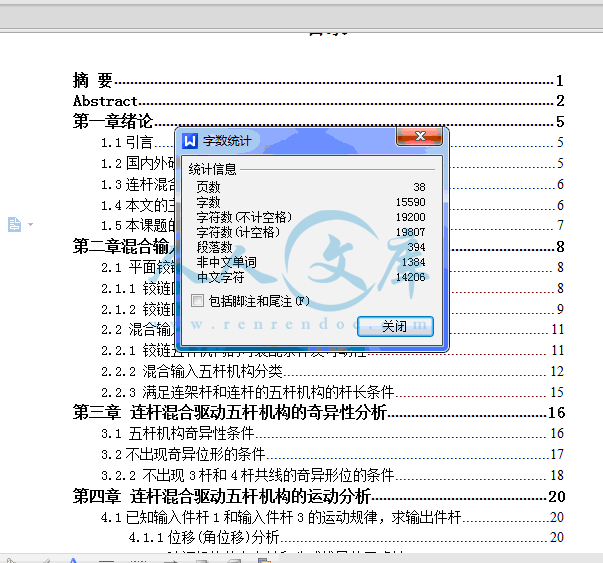
38页 15000字数+说明书+外文翻译译文+7张CAD图纸【详情如下】

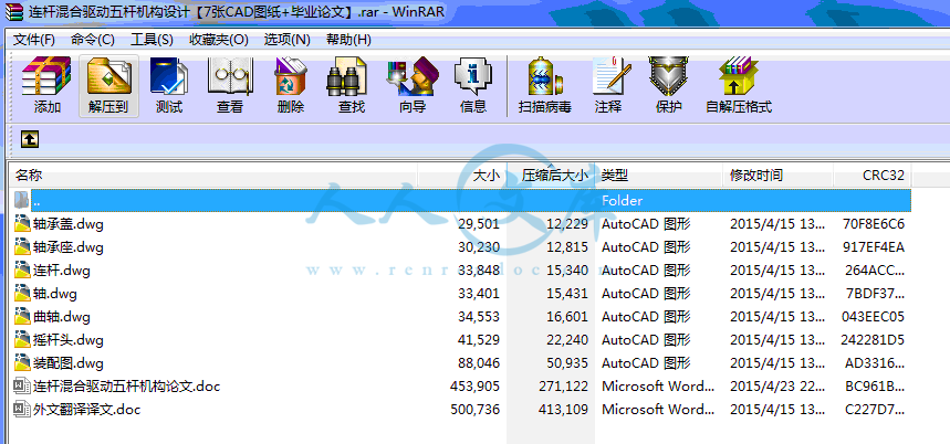
外文翻译译文.doc

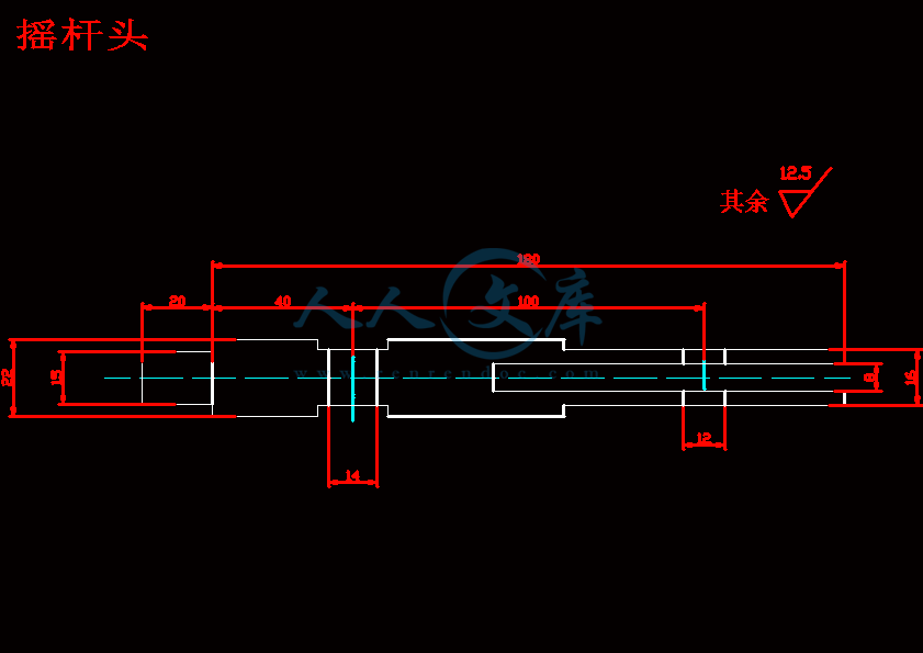
摇杆头.dwg

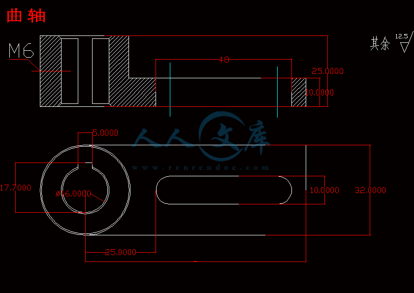
曲轴.dwg

装配图.dwg

轴.dwg

轴承座.dwg

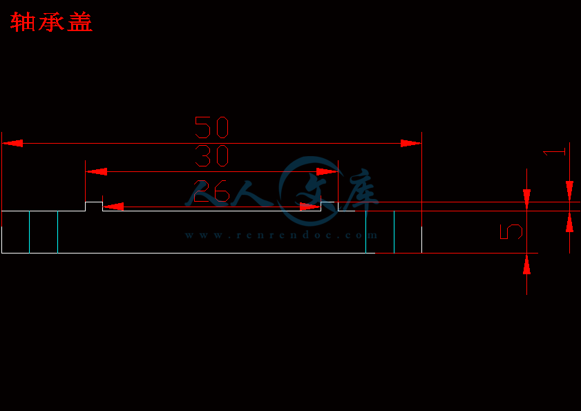
轴承盖.dwg

连杆.dwg

连杆混合驱动五杆机构论文.doc
摘 要

本文以两曲柄分别为连架杆和连杆的一类混合输入五杆机构作为研究对象,围绕此机构对混合驱动可控机构的结构学、运动学和优化综合问题进行了研究。内容为:

1) 从机构的装配条件出发,对机构进行可动性分析,确定了该曲柄— 连杆机构的双曲柄存在条件。

2) 对该机构进行奇异性分析,得出该机构出现奇异位形的两种类型。

3) 分别对机构进行正运动学和逆运动学分析,并通过算例验证机构的存在性和公式推导的正确性。

4) 应用上述分析结果,对该曲柄—连杆机构进行优化综合。针对两种不同的运动类型,分别建立了基于正运动学分析和逆运动学分析的优化综合数学模型,为混合驱动可控机构的优化综合提供了理论方法。并通过实例分析证明了优化后的机构性能有了很大的改善。

关键词:混合输入五杆机构;奇异性分析;运动分析;优化综合

Abstract

 In this paper, take the hybrid input five-bar mechanism for double crank

based on link-rack ram and linkage as subject investigated. This research is

mainly around this mechanism. Research content is focused on the followings  Firstly, set out from the assembly conditions, them obility of this mechanism was analyzed, the existence condition of this mechanism was determined. Secondly, by analyzing the conditions of singularity, this paper conclude the styles of existing the two kinds of singularity. Thirdly, a nalyse based on for ward kinematic sand inversek in ematics, some examples verify the existence of the mechanism and the correctness of formula deduction. Finally , this paper presents the optimal synthesis of crank-linkage mechanism. Regard two different style as the goal, set up different optimal synthesis model on the base of forward kinematics and inverse kinematics analyses. Offered the theory method for the Optimal shnthesishy brid-drivenand controlled mechanism. The results of optimal synthesis example sverifies the institution performance have a great improvement after optimization

Key kin words: hybrid analyses input five-bar mechanism; analysis of singularity; ematics ; optimal synthes

目录

摘 要1

Abstract2

第一章绪论5

1.1引言5

1.2国内外研究概况5

1.3连杆混合驱动五杆机构的工作原理6

1.4本文的主要工作内容6

1.5本课题的研究意义7

第二章混合输入可控五杆机构的可动性分析及存8

2.1 平面铰链四杆机构类型分析8

2.1.1 铰链四杆机构Grashof准则及可装配条件8

2.1.2 铰链四杆机构的两开链机构工作空间位置关系9

2.2 混合输入铰链五杆机构类型11

2.2.1 铰链五杆机构的可装配条件及可动性11

2.2.2 混合输入五杆机构分类12

2.2.3 满足连架杆和连杆的五杆机构的杆长条件15

第三章 连杆混合驱动五杆机构的奇异性分析16

3.1 五杆机构奇异性条件16

3.2不出现奇异位形的条件17

3.2.2 不出现3杆和4杆共线的奇异形位的条件18

第四章 连杆混合驱动五杆机构的运动分析20

4.1已知输入件杆1和输入件杆3的运动规律,求输出件杆20

4.1.1位移(角位移)分析20

4.1.4验证机构的存在性和公式推导的正确性22

4.1.4.1 使用Mathcad编程进行运动仿真22

4.2速度(角速度)分析24

4.2.1加速度(角加速度)分析24

4.2.2验证机构的存在性和公式推导的正确性24

4.2.2.1使用Mathcad编程进行运动仿真24

4.3传动角Y分析24

第五章 连杆混合驱动五杆机构的优化综合25

5.1基于正运动学分析的优化综合模型27

5.1.1机构优化综合模型的建立27

5.1.1.1混合驱动破碎机优化设计的参数28

5.1.1.2目标函数28

5.1. 1.3 设计变量28

5.1. 1.4 约束条件28

5.2基于逆运动学分析的优化综合模型28

5.2.1机构优化综合模型的建立29

5.2. 1. 1混合驱动破碎机优化设计的参数29

5.2.1.2目标函数29

5.2.1.3设计变量30

5.2.1.4约束条件30

5.3机构优化方法的确立30

5.4机构优化综合实例30

5.4.1基于正运动学分析的优化综合实例30

5.4.2基于逆运动学分析的优化综合实例31

第六章 技术参数33

第七章 小结34

参考文献36

致 谢38

第七章 小结

混合驱动可控机构是目前机构学研究的前沿方面,它既涉及到传统机构学理论和机构创新设计理论,有涵盖机器人特别是并联机器人中的有关理论。本文以曲柄— 连杆混合驱动可控机构作为研究对象,对该机构的结构学、运动学等问题进行深入的分析研究,得到如下的结论:

对于两曲柄分别为连架杆和连杆的混合输入五杆机构,其分析方法不同于两曲柄都是连架杆的混合输入五杆机构。尤其是奇异性分析时不能利用输出杆的速度雅可比矩阵,因为它的输出杆是定轴转动的,其速度雅可比矩阵行列式的值是恒为零的。本文主要是利用一连杆的传力点速度雅可比矩阵,计算它的行列式的值进行分析,并通过作机构运动简图和

运动连续性原理验证了其正确性。2.利用了矢量投影法和复合三角函数的求导法进行了该类机构的角位移、角速度和角加速度的分析。并用Mathcad进行运动仿真得出各曲线都是续的,同时用几何作图法进一

步验证了机构的存在性和公式推导的正确性。3.分别采用正运动学和逆运动学方法对该机构进行优化综合,建立数学模型,包括确定该机构的

目标函数、设计变量和约束条件等。并通过对算例的优化,确定了该机构的最优参数。

由于时间关系及本人知识水平有限,对该类机构的设计与优化综合的研究仅仅是初步的。为了进一步完善设计和优化深度,可以从以下几个方面开展工作。

(1) 在机构的运动学分析的基础上,可以考虑对机构的运动规律进行深入分析,比如各杆长变化、初始相位角的变化和传动比变化等等对伺服电机驱动曲柄的影响;另外,可以通过研究可控机构的结构参数、可调参数对速度特性的影响,比较这些参数对机构速度特性影响的主次关系,找出其中对特征参数影响较大的敏感参数。在优化时,利用这些结论,针对主要因素进行优化,这样可以大大减少优化设计的盲目性,提高优化效率。

(2) 对机构进行动力学分析。在高速机械和重型机械中,运动构件会产生较大的惯性力和惯性力矩,回转机构运转中产生的惯性力会造成很大

的危害。因此必须通过动力学分析,减小惯性力的不良影响。

(3)多目标优化设计目标函数的研究。由于混合驱动机构性能涉及诸多的影响因素,因此有必要对其他更多的目标函数进行研究,获得更有实用意义的优化模型,以利于实际工程应用。比如加入伺服电机的驱动力矩

考察和伺服电机输出功率与常规电机输出功率的比值考察等等。

(4) 优化设计变量的研究。本文仅以运动学性能作为目标函数,故设计变量为机构的结构参数。当研究多目标优化设计目标函数时,应相应增加设计变量的考察,如伺服电机的驱动力矩和功率分配问题等等。

(4) 优化设计变量的研究。本文仅以运动学性能作为目标函数,故设计变量为机构的结构参数。当研究多目标优化设计目标函数时,应相应增加设计变量的考察,如伺服电机的驱动力矩和功率分配问题等等。

参考文献

[1]陈瑞芳,马履中.平面五连杆机构曲柄存在条件及机构类型的判别方法[J]江苏理工大学学报,1998,1 9 (1)

[2]廖汉元,1999 ,等.两白由度机构的可动性条件[J]武汉冶金科技大学学报(自然科学版),22 (1),57-59

[3]李佳,等.五杆两自由度机构可动性的充分条件[J].武汉冶金科技大学学报,1998, 21(3)

[4]周双林.邹惫君,等.混合输入五杆机构构型的分析[J]上海交通人学学报,2001,35(7 )

[5]程光组,贺惠农。两自由度连杆机构精确实现平面轨迹的研究[J].东南大学学报,1990,20 ( 3) :64-67

[6]杨金堂,邵正宇,吴千城.受控五杆机构实现轨迹的“补偿运动”研究[J].武汉冶金科技大学学报。1999,22( 2):171-174

[7]孔建益,W.Funk.具有一个受控原动件的五杆机构精确实现给定函数的研究[J].中国机械工程1996,7 (专刊):106-108

[8]张新华,等混合驱动机械系统建模的理论依据[J]机械科技与技术,2001, 20 (6)

[9]李学刚,等.混合驱动可控机构的研究现状及发展趋势[J].河北理工学院学报,2004,26 ( 3)

[10]方新国,邹葱君,周双林混合驱动平面两自由度五杆机构的完全分类[J]机械科学与技术,2003, 22( 1)

[11]孟宪举,张策.平面五杆机构的尺度分析[J].机械科学与技术,2002, 22 (2)

[12]周双林,郭为忠,姚燕安.混合输入五杆机构柔性:作空间的分析上海交通大学学报,2001,35( 12)

[13]周A林,邹慧君,郭为忠,姚燕安.平面闭链五杆机构柔性-L作空间的分析[J].上海交通大学学报,2000,34( 10)

[14]田汉民.混合输入五杆机构的分析和综合[J].天津:天津大学,2001

[15]张新华.实现轨迹创成的混合驱动可控机构分析和综合[J].天津:天津大学,2002

[16]吴深,褚金奎.用谐波理论和快速傅立叶变换进行五杆机构的轨迹综合[J].机械科学与技术 ,1999,18( 3)

[17]陆永辉,孟彩芳,张策一种新型混合输入式曲柄压力机的研究[J].锻压机械

[18]李辉,孟宪举,等.混合驱动压力机运动设计的初步探[J]机械设计与研究

[19]王生泽,等.可控连杆机构动力学分析的一般方法研究[J].机械设计与研究,2002(增刊)

[20]马承文.邹蔽君,方新国.平面五杆机构的惯性力平衡问题的研究[J].机构设计与研究,2002 , 18 (4)

内容简介:
机械装备的发展 一机械装备的应用近十几年来,随着计算机技术和现代控制理论等相关科技的迅速发展,以数控加工为代表的柔性加工日趋完善,基本上实现了自由曲面形状加工阶段的自动化,但其精加工主要还依靠熟练工人的手工操作。由于手工操作生产效益低下,加工质量不稳定,难以适应自由曲面低成本、短周期、高质量的要求,研究一种高效自动化的研抛设备势在必行,本研究针对自由曲面研抛加工所开发的虚拟轴混联机床就是为了适应这种需求。二状态分析本处所开发的是并联、串联有层次联结在一起的混联机床。通过大量文献阅读,建立了各种并联机构模型,运用 Adams 软件对各种并联机构模型进行分析,证明了3PTT运动副可以实现动平台三维空间运动。用 Adams 软件建立的该机床并联机构模型,并进行自由度问题研究和动平台的运动分析。仿真结果表明,该并联机构具有三个自由度,动平台是平动的运动状态。三、自由曲面研抛机床的位姿分析 根据该机车的运动特性,利用解析法建立并联机构的正解方程,首先建立并联机构的解析图形,如图2所示。图2 研抛机床并联机构解析图两端取模平方知:利用齐次变换的方法建立了自由曲面研抛机床串联机构的位置正解,并将串并联机构通过动平台为纽带,得到机床的位置正解。运用欧拉角表达研抛工具的轴线姿势,发现该轴线姿势只与串联机构有关,而与并联机构无关。四、自由曲面研抛机床的动力学分析及其仿真机床的动力学研究,包括机构惯性力计算、受力分析、动力平衡、动力学模型建立、计算机动态仿真等。特别是在机器的运行速度不断提高的情况下,动力学问题的重要性就显得尤为突出,由于计算机的不断发展,使动力学计算、分析、模拟的手段逐步实现了现代化。对机构动力学研究的深入,促进了机器的运转速度进一步提高,对机器的控制提供较为精确的理论基础。五、自由曲面研抛机床结构的研究机床的研制分为二大部分:一是确定其机械结构方案包括机床机架设计;动平台设计;终端执行器设计等。二是研制控制电路和控制软件等。机床应有三个性能指标:对称性、工作空间、各向同性的基础上来设计混联机床。自由曲面研抛机床的主、俯视图如图 3 所示。图3 自由曲面研抛机床的主、俯视图六、结论(1)通过“3 并联轴+2 串联轴”的五坐标联动,用并联机构控制研抛工具的位置,用串联机构控制研抛工具的姿势,有效地拓展了研抛加工作业空间。(2)建立了 3PTT 并联机构 ADAMS 机构学模型,进行了自由度问题的研究。仿真结果表明: 3PTT 并联机构是平动的机构。(3)应用解析法推导了机床的并联机构的位置正解;利用齐次变换的方法建立了自由曲面研抛机床串联机构的位置正解。运用欧拉角表达研抛工具的轴线姿势,发现该轴线姿势只与串联机构有关,而与并联机构无关。(4)基于影响系数理论与拉格朗日方程,推导出了串、并联机构动力学方程,并建立了 ADAMS 动力学仿真模型,仿真结果表明:该机床在 x、y、z 三个方向上的速度、加速度差异很大。如果在 z 方向需要大的速度和加速度,三个滑块均需加同一方向的力,数值相差要足够小,在 x、y 方向需要较大的速度和加速度时,在三个滑块上力的数值要相差足够大。(5)在自由曲面虚拟轴混联研抛机床的结构、运动学与动力学研究以及前人关于研抛理论的工作基础上,开发了自由曲面虚拟轴混联研抛机床的样机。串-并混联研抛机床运动与控制研究1994 年在芝加哥国际机床展览会(IMTS94)上,美国的 Ingersoll 和 Giddings & Lewi公司分别首次展出了名为 Hexapod 和 Variax 的并联机床,引起举世关注。并联机床以空间并联构型为基础,打破了近两个世纪以来单一的以笛卡尔坐标直线位移为基础的串联机床结构和运动学原理,被誉为“本世纪机床机构的最大变革与创新”、“21 世纪的机床”。其后,意大利、日本、俄罗斯、挪威、瑞士、瑞典、丹麦等国的制造商竟相研发并联机床。1997 年底,清华大学和天津大学联合研制出了我国第一台并联机床 VAMT1Y。与传统的串联构型机床相比,纯并联构型的并联机床在结构及运动特性上具有刚度重量比大,运动部件质量小、响应速度快,误差累积小,可以很容易地实现 6 轴联动,运动学逆解求解容易、便于实现实时控制,机床结构简单,技术附加值高等优点。但并联机床同时也存在着工作空间小,运动学的正解求解困难,控制复杂,各轴间存在着深度的非线性运动耦合,运动学标定困难,机床的刚度和运动精度不高等缺点。为克服并联机床的缺点,串-并混联式机床应运而生。混联机床几乎继承了并联机床的全部优点,同时其工作空间增大,运动学正解的求解困难程度及控制复杂程度均明显降低。尽管其刚度和运动学精度仍不如串联机床高,但已显示出强大的生命力。目前,商品化的并联机床已投入使用。课题组通过多年的研究发现,研抛属于弹性加工,研抛过程中作用反力较小,因而对机床的刚度要求较低,同时,研抛机床需要在其终端执行器上安装位移-力柔顺控制器,柔顺控制器的安装使研抛加工对机床运动精度的要求被弱化。研抛加工所具有的这些工艺特性,使得串-并混联机床扬长避短,可以在研抛加工中得到较好的应用。基于对吉林省科技发展重点规划课题“精密自动研抛加工模具自由曲面的虚拟轴专用机床”的研究(机床照片见图 1),本文就串-并混联研抛机床的概念设计、运动学分析、插补控制、研抛实验等问题展开研究。对串联构型、并联构型、混联构型机床的结构特性、运动特性、控制特性等内容进行了分析比较,选定在并联 3 自由度平动平台上串联 2 回转自由度的串-并混联形式作为自由曲面研抛机床的构型。机床结构见图 2。对 3 自由度平动平台的支链结构形式进行了分析。通过齐次坐标变换方法,从支链平台结构位姿变换及其空间几何关系分析入手,建立了三支链并联平台的封闭位置关系,得出了以虎克铰为联接关节条件下 3 自由度平动平台的最简单构型形式和平台工作空间与平台机构体积比值最大条件下的结构参数配置。基于并联平台封闭位置关系,给出了机床的运动学正解,并对机床工作空间的形状、构成进行了剖析。本文所述构型形式的研抛机床具有由三段圆弧面构成的柱形工作空间,工作空间的上顶和下底均为由四个球弧面构成的复合曲面。首次将工具灵活性的概念引入机床的工作空间分析,并按照研抛工具所具有的灵活程度,将机床工作空间划分为完全灵活工作空间、大部分灵活工作空间、小部分灵活工作空间和不灵活工作空间四个子区。通过推理,得出了机床完全灵活工作空间的主要影响因素是研抛工具杆长度的结论。机床工作空间形式及构成见图 3。基于并联平台封闭位置关系和研抛工具的位置-姿态要求,对机床运动学逆解的构成及求解方法进行了研究。由于研抛姿态角1的存在,工具杆轴线可以形成一个以1为半角的姿态圆锥,致使机床的运动学逆解具有多值、不确定性。为使机床的运动学逆解合理、唯一,需添加工艺和运动限定条件。本文对研抛正压力与研抛姿态角之间的关系、研抛线速度与研抛姿态角之间的关系进行了分析,提出了满足研抛正压力和研抛线速度双重控制要求的1选择工艺限定条件,并基于对加工效率、运动干涉等问题的考虑,提出了限定姿态圆锥使用范围的运动条件。综合考虑,提出了研抛工具姿态的选择控制策略,同时给出了机床各种灵活程度工作空间内运动学逆解的求解方法。姿态圆锥及其可选用的范围见图4 和图 5。对离线插补和在线插补的工艺特性进行了分析比较,结合目前插补控制的发展趋势,选择在线的直接插补作为新开发数控系统的插补控制方式。并结合 NURBS 曲面的参变量定义域特性,给出了 NURBS 曲面研抛的路径规划方式。对研抛轨线行间距与表面许用残留高度误差、研抛工具半径、曲面曲率半径之间的关系(图 6),插补步长与表面加工误差、研抛工具半径、曲面曲率半径之间的关系(图 7)行了较为深入的分析,找出了两类加工误差的主要影响因素,并据此提出了针对粗研磨和精整抛光的研抛轨线行间距、插补步长确定方法。五坐标虚拟轴研抛机床数控系统的研究一、说明我国于 2001 年正式加入 WTO 以来,经济发展迅速。随着汽车、航空航天以及一批高新技术产业的发展,含有自由曲面的零件所占的比例越来越大,对自由曲面的加工质量和效率要求也越来越高。但是目前对自由曲面的精加工主要还依靠熟练工人的手工操作。由于手工操作生产效益低下,加工质量不稳定,难以适应自由曲面低成本、短周期、高质量的要求,研究一种高效自动化的研抛设备势在必行。本文针对用于自由曲面研抛加工的 JDYP51 型五坐标虚拟轴研抛机床,研究出了一种基于 PMAC 的开放式数控系统。二、虚拟轴机床机构设计的分析本课题所研究的是并联、串联组合在一起的混联机床,该机床为 3+2 式虚拟轴机床,即 3 个并联轴实现 X、Y、Z 向 3 个坐标运动,并联机构带动动平台实现平动,在动平台上安装 2 自由度串联机器手,串联机构下加装主轴装置。用此机床进行模具自由曲面的研抛加工。机床照片如图 1 所示,虚拟轴机床的总体结构如图 2 所示,它的并联机构由静平台、动平台和三个导轨立柱滑块支链相结合的机构组成 ,支链采用定长杆,各杆件一端与滑块,另一端与动平台用虎克铰连接,滑块由伺服电机和滚珠丝杠螺母副驱动,沿导轨作上下移动。机床的串联机构连接在动平台上,由两个转动关节构成,分别绕轴转动来调整研抛工具的位姿。以上所述即为并联机构的位置关系,同时可以利用齐次变换的方法建立机床串联机构的位置方程,并将串并联机构通过动平台为纽带,得到机床整体的位置关系。三、开放式数控系统的硬件设计与实现我们通过对 JDYP51 型虚拟轴研抛机床的研究,设计使用了一种基于PMAC 的开放式数控系统。根据此数控系统所设计的数控装置目前已经完成,如图 4 所示,控制装置区域划分由上至下为:实时显示区,饲服控制区,控制电路区,核心控制区和主轴控制区。制机、PMAC 运动控制器、双端口 RAM(DPRAM)、伺服单元及交流伺服电机等组成。图中的虚线将上位机和下位机的功能模块分开,实线框以外部分为系统的外部设备。由框图可以看出,PMAC 控制器与主机(IPC)之间的通讯采用了两种方式。一种是总线通讯方式,另一种是利用 DPRAM 进行数据通信,主机与 PMAC 运动控制器主要通过 ISA 总线通讯,至于控制器和电机的状态、所处的位置、速度、跟随误差等数据则通过 DPRAM 交换信息。图4 JDYP51 NC 装置四、开放式数控系统的软件研究虚拟轴机床数控系统实现正常工作,需要三个部分的系统软件来执行:IPC的用户界面应用程序;IPC 与 PMAC 上下位机间的通讯程序;PMAC 中对各种输入、输出量进行监控的 PLC 程序。其中通讯程序的开发工作量最大、最困难、也最具有技巧性,Delta Tau 公司提供的 Pcomm32 已经对通讯程序进行了充分的开发,我们可以通过 Pmac.dll 进一步利用。人机界面应用程序采用Visual C+6.0 语言进行开发。PLC 程序采用 Delta Tau 公司提供的语言进行设计开发。系统软件工作机理如图 6 所示,五、结论本课题对 JDYP51 型五坐标虚拟轴研抛机床的数控系统进行了研究和设计,建立了一种基于 PMAC 和 IPC 的双 CPU 开放式数控系统,完成了机床的数控装置,并通过此数控装置对机床进行了初步的调试和试运行,实现了基本的运行要求。本论文主要的研究工作及研究成果如下:1对虚拟轴机床机构整体设计和工作原理进行了分析研究,通过分别对机床并联机构、串联机构和主轴研头的位置解析,得到机床输入与输出的位置正逆解关系式,为数控系统对机床的轨迹运动控制提供了基础。2对可编程多轴运动控制器(PMAC)进行了深入系统的研究,针对本虚拟轴机床设计开发了一种基于 PMAC 和 IPC 的双 CPU 开放式数控系统硬件结构,根据硬件设计要求选择了相应的硬件设施和电子器件,组建完成了数控系统的控制装置。3对 CNC 系统软件结构与功能做了深入的研究,建立了数控系统软件结构框架。根据数控系统硬件的结构设计,提出了系统软件工作机理,同时参与了人机控制界面的开发并对系统软件设计做了进一步的研究。此控制界面软件实现了部分的硬件软件化,将部分控制按钮和指示灯等硬设施转化为软件控制,同时可以根据需要添加多个 I/O 通道,具有良好的开放性和实时性。4通过数控系统的控制装置对 JDYP51 型五坐标虚拟轴研抛机床进行了调试,并在调试过程中完成了数控系统的参数设置与调整,初步完成了机床的合理运行。通过对饲服系统的 PID 调节及位置速度反馈的分析结果,实现了较为理想的运动状态。Polishing Machine DevelopmentYudy and development on hybrid virtual axis machine tool forpolishing free-form surfaces1 IntroductionWith the development of automobile industry,electric industry and some new high-techindustries ,the larger is the proportion of NC machining parts with free-form surface in all, thehigher and higher requirements are made for quality and efficiency of machining on free-formsurfaces. After the roughing method is used, precision machining, such as polishing and polishing,is necessary to obtain required workpiece surfaces. Near for over ten years, With the developmentat a high speed in relevant science and technology, such as the technology of the computer andmodern control theory, etc., flexibility machining become more perfect. The automatic machiningof free-form surfaces come to true basically. However, these subsequent processes of precisionmachining still depend mainly on the handwork of skilled mechanists. Productivity effect ofhandwork is very low and its quality is unstable. As to the machining of free-form surfaces, lowcost and short period and high quality were its main aim. As a result of that, the research of a kindof increasingly automated polishing equipment is imperative. Series-parallel virtual axis machine tools for polishing free-form surfaces meets the requirement .2 Work principle and degree of freedom study on hybrid virtual axis machine tools for polishing The sliding block that was drived by servo electromotor and rolling screw thread-nut move up and down along with rail. The inseries mechanism of the machine tool was linked with move platform. It was made up of two rotation joints. The pose of polishing tools was adjusted around axis. The structure principle of the machine tool is shown as Figure.1.3.Position and pose analysis of series-parallet virtual axis machine tool for polishing free-form surface.Fig2Model of parallel mechanism was established by ADAMS software, It is analyzed out that the parallel mechanism has three DOF and the motion status of move platform is linear motion. it is shown As Fig2Positive position solution of inseries mechanism of machine tools for polishing free-form surfaces was established through homogeneous transformation of the coordinate frames. Inseries and parallel mechanism were regarded moving the platform as the tie, so positive position solution of machine tools was got. Axes position of polishing tools is related to inseries mechanism but not parallel mechanism. It was proved by Euler angles.4 kinetics analysis and simulation of series-parallel virtual axis machine tools for polishing free-form surfaces Kinetics analysis of machine tools included inertia force calculate, force analysis, balance of motive force, establishment of kinetics model, dynamic simulation with computer,etc. In the case of increasing velocity of machine tools, the importance of kinetics questions become particularly outstanding. Because of the uninterrupted development of computer, the methods of kinetics calculate and analysis and simulation become modernization. With the deep study of kinetics, the velocity of machine tools was further improved. It offers theory basis for control of the machine tools.The move platform can only realize linear motion in 3D space. There is not rotation kinetic nergy. Then the kinetic energy of move platform is design of machine tools shelfand . 5.Stand on structure of series-parallet virtual axis machine tool for polishing free-form surface.The front view and bottommove platform and end effector,view of the polishing machineetc. Second, there are study andtool for free-form surfaces manufacture of control circuitand so on. There are three perfor-mance indexes :symmetry.worksp-ace.isotropy. On the basisof these, series-parallel machine tools were designed. Overall appearance of machine tools must be aesthetic. There are another requirements with good igidity and stability and enough operation space. Front view and bottom view of machine tools for polishing free-form surfaces are shown as Figure.3.6 conclusion1. Five coordinates axes move together throng three parallel axes and two inseries axes. The position of polishing tools was controlled by parallel mechanism and the pose was controlled by parallel mechanism. Thus, the work space for polishing was increased effectually.2.3PTT parallel mechanism structure model of Adams was established. The problem of degree of freedom was studied. The simulation shows: 3PTT parallel mechanism move linearly.3.Analytics methods were applied to deduct the positive position solution of machine toolsparallel. Positive position solution was obtained by making use of homogeneous transformation of the coordinate frames. Axes pose of polishing tools was expressed by Euler angle. It is shown that the axes pose is related to inseries mechanism,but not parallel mechanism.4.On the basis of influence coefficient theory and Lagrangian equation, it was deducted that the kinetic equation of inseries and parallel mechanism. Kinetic simulation model was established by Adams. The simulation shows: there are much difference of velocity and acceleration in X,Y, Z direction of the machine tool. If it is required that high velocity and acceleration in Z direction, the same direction forces were added to the three siding blocks. The difference of value should be small enough. The difference of force value on the three sliding blocks should be big enough, if requiring high velocity and acceleration in X, Y direction.5.Through studying the structure and kinematics and kinetic of the inseries-parallel virtual axis machine tool for polishing free-form surfaces and on the working foundation of polishing theory of forefathers, it was developed that the sample of inseries-parallel virtual axis machine tool for polishing free-form surfaces.Keywords: parallel mechanism helix theory degree of freedominfluence coefficient free-form surfaces polishingvirtual axis machine toolStudy on the Kinematics and Interpolation Control of the Series-Parallel Hybrid Polishing Machine ToolIn 1994 on the Chicago international exhibition of machine tool (IMTS94), the parallel machine tools of Hexapod and Variax are displayed by the Ingersoll and Giddings & Lewis company of America for the first time, and it is paid close attention by the whole world. Based on the three dimensional parallel mechanism, the parallel machine tool founds a new principle of the construction and the kinematics for the machine tool, and is known as the biggest transformation and innovation of the mechanism for machine tool in this century , the machine tool of the 21 century . In after years, the manufacturers of Italy, Japan, Russia, Norway, Switzerland, Sweden and Danish etc. develop parallel machine tool competitively. In the end of 1997, the first parallel machine tool VAMT1Y of our country was developed by the Tsinghua University and Tianjin University jointly.Compared with the traditional series machine tool, the parallel machine tool has many merits on the aspect of the structure and the kinematics characteristic such as higher proportion of the rigidity and weight, less quality of the moving parts, rapider respond speed, less error accumulation, easier realization for 6 axles uniting to move, easier calculation for inverse kinematics result that is expedient for real time control, simpler structure of machine tool, higher technical additional value and so on. However, the parallel machine tool has also the disadvantages such as smaller work space, more difficult calculation for forward kinematics result, deeper nonlinear coupling among each axis and more complex control for interpolation, more difficult kinematics marking, weakIt is against the shortcomings of the parallel machine tool that the hybrid machine tool with series-parallel conformation has been developed.The series-parallel hybrid machine tool has inherited all advantages of the parallel virtual axis machine tool nearly, and its workspace to be increased, the difficulty to calculate the forward kinematics result and to control the machine tool to be reduced. For these reasons, theer rigidity and movement precision of the machine tool. series-parallel hybrid machine tool has shown powerful vitality though its rigidity and movement precision is still lower than the series machine tool. Observing the conformation of the machine tools to be made recently, mostly of them are series-parallel one.Studying the polishing for many years, the group knows that the polishing machining belongs to flexible machining. In the polishing process, the requirements for the rigidity and the movement precision of the machine tool are both lower because the active force of the polishing process is smaller and the displacement-force obedience controller is installed in the bearing rod of the polishing tool. For these reasons, the series-parallel hybrid machine tool can be used as a better polishing machine tool.Based on the polishing machine tool made by the group, these questions such as the conception design, the kinematics analysis, the interpolation control and the polishing experiment of the series-parallel hybrid polishing machine tool have been discussed deeply in the paper. Fig. 1 is the photo of the machine tool.After analyzing the structure characteristic, the kinematics characteristic and the control characteristic among the series conformation, the parallel conformation and the series-parallel conformation, select the conformation connected 2 series rotation mechanisms on the 3 DOFS translation moving platform as the conformation of the polishing machine tool. Fig. 2 is the mechanisms of the machine tool.The chain structure of 3 DOFS translation platform is analyzed. Through the method ofhomogeneous transformation and the analysis of dimensional geometry connection about the position-posture of the parallel platform, the closed position connection of the parallel platform is given out, and based on it, the conclusion is revealed that the most simple mechanism of the 3 DOFS translation platform is 3 single-link chains mechanism which is symmetrical in space and jointed by Hook joints. The structure parameters are discussed under the condition of the biggest ratio between the workspace and the structure space of the platform.Based on the closed position connection of the parallel platform, the forward kinematics result of the machine tool is given out, and the workspace of the machine tool is discussed in form and shape. The workspace of the series-parallel hybrid virtual axis polishing machine tool is a column space that is made up of 3 circular-arc surfaces, and its top and bottom are both the complex curved surface consists of 4 ball-arc surfaces. The concept of tool flexibility was introduced firstly in the analysis of machine tool workspace, and according to it, the workspace of the machine tool is divided into four kinds of flexible workspace, the full flexible-workspace, the most flexible-workspace, the fraction flexible-workspace and unhandy workspace. The main influence factor on the full flexible-workspace of the machine tool is the bearing rod length of the polishing tool. The workspace of the machine tool is shown as Fig. 3.Based on the closed position connection of the parallel platform and the requirement of position-posture on polishing tool, the inverse kinematics result of the machine tool is analyzed in form and calculating method. Being the polishing posture angle 1, the axes of the polishing tool bearing rod can form a cone with half-angle 1(shown as Fig. 4). That makes the inverse kinematics result of the machine tool have the characteristic of more values and uncertainty. In order to make the inverse kinematics result uniquely, the technical restricting conditions and the motion restricting conditions should be appended. The relations among the active force, the polishing velocity and the polishing posture angle 1 are analyzed, and the technical restricting conditions, the motion restricting conditions are put forward. The method of calculating the polishing posture in four kinds of flexible workspace is introduced. After that, the inverse kinematics result of the machine tool is given out. Fig. 5 is the semi-cone that the axes of the polishing tool bearing rod should be located on.According to the property of the variable definition region of the NURBS curved surface, the polishing path has been planned. For the reason of its excellent property, online direct interpolation control is chosen as the interpolation control method of the new developing system.Based on the analysis about the row space of the polishing trace and its influence factor, the interpolation step size and its influence factor, the methods how to determine the row space of the polishing trace and the interpolation step size are given out. The relation between row space and radius of the curved surface is shown in Fig. 6, and the relation between interpolation step size and radius of the curved surface is shown in Fig. 7.Research on CNC System of five-coordinate Virtual Axis polishing Machine Tool1IntroductionSince our country was affiliated to WTO in due form in 2001, the economic development is speedier. With the development of automobile industry, aeronautics and astronautics industry and some new high-tech industries, the larger is the proportion of NC machining parts with free-form surface in all, the higher and higher requirements are made for quality and efficiency of machining on free-form surfaces. However, these subsequent processes of precision machining still dependmainly on the handwork of skilled mechanists presently. Productivity effect of handwork is very low and its quality is unstable. As to the machining of free-form surfaces, low cost and short period and high quality were its main aim. As a result of that, the research of a kind of increasingly automated polishing equipment is imperative. This paper regards the JDYP51 model five-coordinate virtual axis polishing machine tool for polishing free-form surfaces. We have researched a kind of open architecture CNC system which is based on PMAC.2Mechanism design analysis of virtual axis machine toolThe series-parallel machine tool, which is well arranged by in series and parallel, is researched in this dissertation.It is a “3+2” model virtual axis machine tool .Three parallel axis carry out there movements in Xcoordinates、Ycoordinates and Z coordinates. Parallel mechanism drives move platform to move flatly. In series mechanism which have two degree of freedoms is fixed in move platform. principal axis mechanism is fixed with In series mechanism. The machine tool can be used to polish free-form surfaces of mold. the photo of machine tool is shown as Figure1.The whole structure of virtual axis machine tool is shown as Figure2. The parallel mechanism are composed of still platform, move platform, three poles and a chain that is fix long pole. At one end of every pole, a sliding block is linked. At the other end of it, the move platform is linked by Huke joint. The sliding block that is drived by servo electromotor and rolling screw thread-nut move up and down along with rail. The inseries mechanism of the machine tool is linked with move platform. It is made up of two rotation joints. The pose of polishing tools is adjusted around axis.through geometry relation, three kindsof relation between input and export of move platform are obtained.These are position analysis of parallel mechanism.And Positive position solution of inseries mechanism of machine tools is established through homogeneous transformation of the coordinate frames. Inseries and parallel mechanism are regarded moving the platform as the tie, so the position solution of machine tools can be got.3. Design and realization of open NC system hardware Through research on JDYP51 model five-coordinate virtual axis polishing machine tool, a kind of open NC system is designed on the basis of PMAC.NC equipment has been already manufactured, which is shown as figure 4. The control equipment was divided as: real time show area, servo control area, control circuit area, core control area and main spindle control area.Function module of the machine upside and underside are divided by dashed shown as figure 5.The part outside solid line frame is the exterior system equipments. It is shown as frame diagram that there are two communication mode between PMAC and IPC. One is bus communication mode, the other is DPRAM data communication mode. The communication between IPC and PMAC is realized by ISA bus. The message between controller and the data of position and velocity and following error of electric engineering exchanged.4.Software research on open NC systemThree parts of system software are required to realize the normal work of the NC system of virtual axis polishing machine tool, which are user interface application program of IPC , communication program between IPC and PMAC upside and
温馨提示:
1: 本站所有资源如无特殊说明,都需要本地电脑安装OFFICE2007和PDF阅读器。图纸软件为CAD,CAXA,PROE,UG,SolidWorks等.压缩文件请下载最新的WinRAR软件解压。
2: 本站的文档不包含任何第三方提供的附件图纸等,如果需要附件,请联系上传者。文件的所有权益归上传用户所有。
3.本站RAR压缩包中若带图纸,网页内容里面会有图纸预览,若没有图纸预览就没有图纸。
4. 未经权益所有人同意不得将文件中的内容挪作商业或盈利用途。
5. 人人文库网仅提供信息存储空间,仅对用户上传内容的表现方式做保护处理,对用户上传分享的文档内容本身不做任何修改或编辑,并不能对任何下载内容负责。
6. 下载文件中如有侵权或不适当内容,请与我们联系,我们立即纠正。
7. 本站不保证下载资源的准确性、安全性和完整性, 同时也不承担用户因使用这些下载资源对自己和他人造成任何形式的伤害或损失。
提示  人人文库网所有资源均是用户自行上传分享,仅供网友学习交流,未经上传用户书面授权,请勿作他用。
关于本文
本文标题:连杆混合驱动五杆机构设计【7张CAD图纸+毕业论文】
链接地址:https://www.renrendoc.com/p-427546.html

官方联系方式

2:不支持迅雷下载,请使用浏览器下载   
3:不支持QQ浏览器下载,请用其他浏览器   
4:下载后的文档和图纸-无水印   
5:文档经过压缩,下载后原文更清晰   
关于我们 - 网站声明 - 网站地图 - 资源地图 - 友情链接 - 网站客服 - 联系我们

网站客服QQ:2881952447     

copyright@ 2020-2025  renrendoc.com 人人文库版权所有   联系电话:400-852-1180

备案号:蜀ICP备2022000484号-2       经营许可证: 川B2-20220663       公网安备川公网安备: 51019002004831号

本站为文档C2C交易模式,即用户上传的文档直接被用户下载,本站只是中间服务平台,本站所有文档下载所得的收益归上传人(含作者)所有。人人文库网仅提供信息存储空间,仅对用户上传内容的表现方式做保护处理,对上载内容本身不做任何修改或编辑。若文档所含内容侵犯了您的版权或隐私,请立即通知人人文库网,我们立即给予删除!