目录.doc

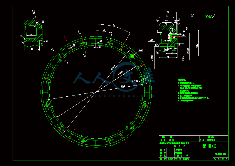
包钢烧结圆筒混合机设计【9张CAD图纸+毕业论文】【答辩优秀】

收藏

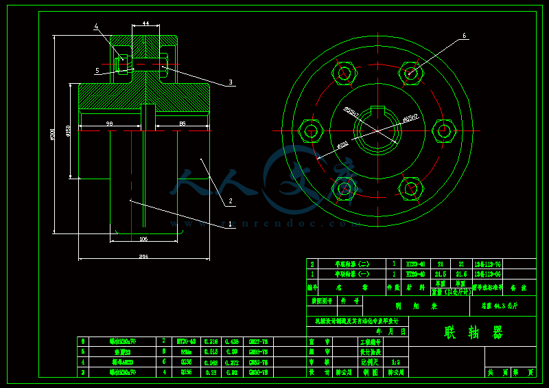
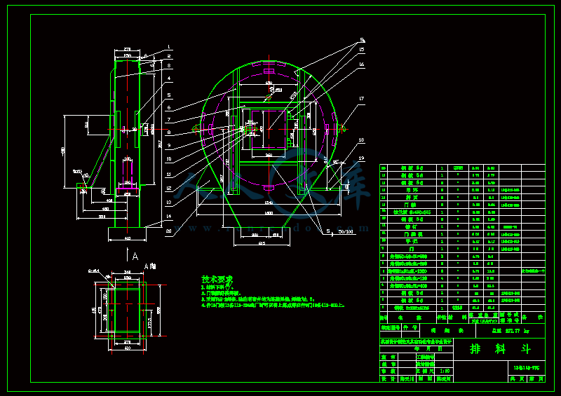
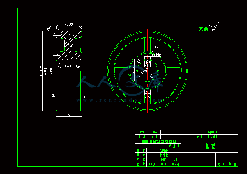
压缩包内文档预览:
预览图 预览图 预览图 预览图 预览图 预览图 预览图
编号:428159    类型:共享资源    大小:1.46MB    格式:RAR    上传时间:2015-04-27 上传人:好资料QQ****51605 IP属地:江苏
45
积分
关 键 词:
包钢 烧结 圆筒 混合 设计 全套 cad 图纸 毕业论文 答辩 优秀 优良
资源描述:


【温馨提示】 购买原稿文件请充值后自助下载。

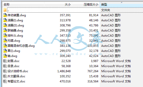
[全部文件] 那张截图中的文件为本资料所有内容,下载后即可获得。


预览截图请勿抄袭,原稿文件完整清晰,无水印,可编辑。

有疑问可以咨询QQ:414951605或1304139763

摘 要


  圆筒混合机是烧结厂主要设备之一。一次混合机主要作用是将物料混匀及湿润,二次混合机主要是对物料进行制粒,使物料满足成分均匀、水分适中、透气良好的要求。混合料的进料由皮带机和漏斗两种形式,将料送入圆筒混合机的进料端,通过筒体的旋转,物料在筒体内呈螺旋状运动,在运动的过程中使混合料形成“滚落”状,从而完成物料的混合、湿润、制粒、混匀,通过圆筒混合机排料端的溜槽排到皮带输送机上。

阐述了混和、制粒时物料的运动过程,对圆筒混合机内物料运动的几种状态进行分析。描述了影响圆筒混合机混匀、制粒的因素。分析了圆筒混合机筒体各部分的力学性能,提供了相应的受力的计算方法。然后阐述了圆筒混合机传动装置的受力分析和计算方法,主要是对轴的安全性能的校核,保证传动的可靠性。


关键词  圆筒混合机;传动;受力分析;校核


Abstract

Drum blender is one of the most important equipments in modern iron and steel corporation. The primary role of the first mixer is mixing materials and humid. The Mixer of second major is used to proceed granulation. Uniform material to meet constituents, moderate water, good ventilation requirements. Mixture of feed material from the belt and a funnel in two forms, Will be expected into the cylinder-feed mixer Through the revolving cylinder Materials in the cylinder show a spiral movement movement in the process of mixture formation is tumble accusation .Thus completing the mixed materials、 humid、 granulation and blending, Through mixing drum nesting end of the chute into the conveyor belt.

The mixing and rolling process of material is explored. Several characteristics of material motion in drum blender are carefully analysis. Influence factors on material mixing and balling is described. Analysis of the mixing drum cylinder parts of the mechanical properties. To provide the corresponding force method of calculation. Then the mixing of the Transmission stress analysis and calculation method are explored the main to the axis is checking at the safety performance, Ensure the reliability of transmission.


Keywords   Drum blender; transmission; stress analysis; check


目录

摘要…………………………………………...……………………I

Abstract.............................................................................................II

第一章  绪论...................................................................................1

 1.1  引言 ....................................................................................1

 1.2 圆筒混合机的发展.......................................................................1

  1.2.1圆筒混合机概述........................................................................3

  1.2.2 圆筒混合机的工作原理.................................................................3

  1.2.3 一次混合机..................................................................................3

 1.3 圆筒混合机的结构.......................................................................4

1.3.1 入料装置.....................................................................................4

1.3.2 筒体部分.....................................................................................4

1.3.3 传动装置.....................................................................................5

1.3.4 支撑装置.....................................................................................5

1.3.5 给料装置.....................................................................................5

1.4 圆筒混合机的工艺布置...............................................................5

1.4.1支撑形式.....................................................................................6

1.4.2传动形式.....................................................................................6

1.5 影响物料混合及造球的因素.......................................................6

1.5.1原料性质的影响...........................................................................6

1.5.2加水润湿方法..............................................................................6

1.5.3混合、制粒效果..........................................................................7

1.5.4混合制粒时间..............................................................................7

1.5.5混合机的安装倾角及充填率.........................................................7

1.5.6添加物........................................................................................8

1.6 作用及意义...................................................................................8

第二章  圆筒混合机电机功率计算..............................................9

2.1 混合机传动总功率的分析...........................................................9

2.2 圆筒混合机内物料运动过程分析..............................................10

  2.2.1物料转动所消耗功率的计算.........................................................10

  2.2.2一次混合机的最佳参数选择.........................................................12

   2.2.3二次混合机的最佳参数选择.........................................................12

2.3 计算物料重心上移所消耗的功率..............................................13

    2.3.1计算物料滚动时内摩擦所消耗的功率...........................................15

    2.3.2计算转动物料所消耗的功率........................................................15

2.4 计算克服支承系统的摩擦所消耗的功率..................................15

    2.4.1计算托轮上所消耗的功率............................................................16

    2.4.2计算挡轮上所消耗的功率............................................................17

    2.4.3计算支承系统所消耗的总功率.....................................................17

2.5 计算总功率..................................................................................17

2.5.1圆筒混合机的电机功率计算.........................................................18

2.6 本章小结......................................................................................19

第三章 传动装置的总体设计...........................................................21

3.1 分析传动装置的工作情况..........................................................21

    3.1.1传动装置示意图..........................................................................21

    3.1.2传动形式....................................................................................21

3.2 根据传动装置的组成和特点确定传动方案..............................21

   3.2.1圆柱齿轮减速器传动布置形式.......................................................22

3.3 初步确定减速器结构和零部件类型..........................................23

    3.3.1确定传动装置的总传动比和分配各级传动比................................23

    3.3.2计算传动装置的运动和动力参数..................................................24

    3.3.3减速器的选择.............................................................................24

    3.3.4减速器的校核.............................................................................25

    3.3.5圆柱齿轮减速器箱体设计注意事项..............................................26

3.4 联轴器的选择.............................................................................26

    3.4.1联轴器的附加力矩的计算............................................................26

    3.4.2类型选择的条件..........................................................................27

    3.4.3与电机轴相连的联轴器型号选择..................................................27

    3.4.4与减速器输出轴相连的联轴器型号选择........................................27

3.5 传动齿轮和齿圈的设计.............................................................28

    3.5.1 选定齿轮类型、精度等级、材料及齿数......................................28

    3.5.2 按齿面接触强度设计..................................................................28

    3.5.3 按齿根弯曲强度设计..................................................................30

    3.5.4 几何尺寸计算............................................................................32

3.6 轴的结构设计.............................................................................32

    3.6.1 轴结构设计的一般原则.............................................................32

    3.6.2 初步确定轴的形状及外形尺寸...................................................33

    3.6.3 初步选择滚动轴承....................................................................34

    3.6.4 确定轴上圆角和倒角尺寸..........................................................35

    3.6.5 求轴上的载荷...........................................................................35

3.6.6 按弯扭合成应力校核轴的强度...................................................39

   3.6.7 精确校核轴的疲劳强度..............................................................39

3.7 本章小结....................................................................................42

第四章 设备的使用和维护..............................................................43

4.1 设备的使用................................................................................43

4.2 设备的维护................................................................................43

第五章  结束语.................................................................................44

参考文献..............................................................................................45


内容简介:
圆筒混合机电机功率的计算摘 要 经过一系列地分析推导,归纳出圆筒混合机的驱动马达功率的计算方法,并通过包钢烧结厂1.2m4m型混合机的功率计算,进一步阐明了上述公式的应用方法。关键词 圆筒混合机;电机功率;计算The motor power calculation of cylinder mixerChen Yunchuan(Inner Mongolia University of Science and Technology Engineering SchoolMachinery 04-1 class)Abstract: Method for calculating the power of driving motor for the cylinder mixer is developed by way of a series analysis and derivation and application of the above mentioned formula is further expounded by computation of the power of type 1.2m4m mixer at the Sintering Plant of Baotou steel.Keywords: cylinder mixer; motor power; calculation1 前言由于圆筒混合机具有结构简单、工作可靠、检修维护方便、运行平稳、生产能力大、混合造球好等优点 ,在烧结作业的一、二次混合中得到广泛地应用。但是 ,如何计算传动功率 ,选定电动机的容量 ,以满足生产实际的需要 ,则比较困难。电机常出现的问题,主要表现在: 电动机的温升较高; 减速机的响声异常。通过现场的观察、分析认为是由于电动机的功率不够造成的。实图如下:图.1烧结圆筒混合机2 混合机传动总功率的分析 混合机的传动是由电动机通过一、二级减速机和两组主动托辊、两组被动托辊摩擦传动来实现的,混合机的进料端比出料端高,使整个设备具有一定的倾斜角。经分析可知,驱动圆筒混合机转动所消耗的功率N可按下式来决定: (1)式中 N 驱动圆筒所消耗的功率/ kW N1 筒内物料转动所消耗的功率/ kW N2 筒体克服支承系统的摩擦所消耗的功率/ kW N3 筒体本体转动所消耗的功率/ kW 总传动效率3 圆筒混合机内物料运动过程分析3.1 物料转动所消耗功率的计算物料在筒体内运动是比较复杂的。混合料进入圆筒后,由于与筒壁之间产生摩擦,在圆筒旋转离心力的作用下,附于筒壁并上升到一定的高度,然后靠重力的作用滚下 ,与上升的物料产生相对运动而滚动成球 混合料在多次往复运动的过程中,在轴向分力的作用下,不断向出料端移动。从圆筒的横断面上看,由于混合料层较厚,各部位受力情况相差很大,其上升时达到的高度也不相同 ,并且在圆筒连续旋转的过程中,总是有一部分物料在上升,一部分在下落,物料上升或下落的多少,与圆筒的转速有关。若转速过小,混合料所受到的离心力、圆周力也就过小,物料就不能上升到足够的高度,仅堆积在圆筒下部,这种情况起不到混合与造球的作用。与之相反,若转速过大, 物料所受到的离心力、圆周力过大,致使物料紧贴附于筒壁而带到很高的部位才抛落下来,这种情况也起不到造球的作用。只有在速度适宜时,设备运转安全,混合与造球效果也好,大型混合机一般选用67r/min的速度。经上述分析可知 ,转动物料所消耗的功率 N1应由下式决定: (2)式中 N11 物料重心上移所消耗的功率/kw N12 物料滚动,内摩擦所消耗的功率/ kw物料的受力如下图所示。 1. 筒体 2 物料 图.2 物料受力情况图2中物料所受重力为G,筒体对物料的支持力为N,物料所受摩为F,其中摩擦力FN筒体转速为n(r/min),则其角速度为n/30 (3)为物料位置和筒体中心的连线与竖直方向的夹角,称为物料提升此时物料颗粒法线方向受力方程为N-mgcos=m2R (4)切向方向上受力方程为 F-mgsin=0 (5)将F=N和式(2-2)代入到式(2-3)中得 (m2+mgcos)-mgsin=0 (6)可以看出随着物料的上升,变大,N变小,F也变小,而重力在切线上的分量mgsin则变大。不同性质的物料在圆筒混合机内的运动时,由于物料的不同性质以及及筒体不同的转速、不同的填充率等工艺参数时,物料运功状态大致有六种状态2。分别为Slipping(滑移)、Slumping(阶梯)、Rolling(滚动)、Cascading(小瀑布)、Cataracting(大瀑布)和Centrifuging(离心)。3.2 计算物料重心上移所消耗的功率经过分析论证,物料重心上移所消耗的功率N11 为 :N11 = W1 v/ 102 (7)式中 W1 筒内滚动物料总重/ kg W1= R2L (8) 填充率 R 筒体半径/m L 筒体长度/m 物料容重/ kgv 物料重心线速度c 的垂直分量 (9)式中 n 筒体转速/ rmin-1;rc 物料重心半径/m; 物料料面与水平面的轴角;研究筒内物料的运动可知,动态的比静态的自然堆角要小,这是因为:(1)随着筒体的回转,表面物料层沿斜面滚落下来,滚落部分角称为剪切角,= - ; (2)物料运动中内摩擦减小, 动 = (0.70.9);(3)由于温度、湿度、粒度等的变化 , 与不同。 (10) (11)式中 物料对应中心角的一半/ rad 填充率与的关系由式(7)给出 ,或由表1 查出。把(8)、(9)、(10)式代入(7)中有: (12)3.3 计算物料滚动时内摩擦所消耗的功率(1) 精确计算上升物料与滚动下落物料间内摩擦力是比较复杂的,因为影响的因素较多,而有些因素是随机的,如物料特性、物料滚动状态等。为了计算出内摩擦力的大小,根据实际情况做出如下两点假设:上升物料与下落物料的重量相等;内摩擦力均布在通过重心的圆周上。这样,内摩擦力可由下式求出: (13)式中 F 内摩擦力/ kg 内摩擦系数g 重力加速度 ,取g=9.81m/ 角速度/ rad = n/ 30 (14) (2)内摩擦力对圆心O所产生的力矩 M : (15)M 内摩擦力矩/ kg(3)内摩擦所消耗的功率: (16)把(8)(10)(14)代入式(15)得; (17)3.4 计算转动物料所消耗的功率把(8)、(15)式代入(2)中得: (18)3.5 计算克服支承系统的摩擦所消耗的功率 (19) 托辊上所消耗的功率/ kW; 挡轮上所消耗的功率/ kW。3.6 计算托轮上所消耗的功率(1) 由于4 个托辊承受混合机转动部分全部重量的径向力 ,所以每侧两个托辊上所承受的径向力之和 P1 可由下式求出: (20)式中 径向力/ kg; 托辊滚圈中心连线与垂直方向的夹角/ (); 筒体轴线与水平线的夹角/ (); 筒体及齿圈的重量/ kg;随着混合机的长期使用 ,筒壁内要附着一定厚度的粘着矿 ,因其厚度是随机变化的 ,所以重量确定起来较困难。一般是根据日立造船株式会社的经验和数据来确定其重量: (21)式中 1 粘着矿的松散容重=2750kg/ 筒内粘着矿的厚度,取0.050.15m L 筒体长度/m,一次混合取较大值 ,二次混合取较小值(2) 筒体转动在 4 个托辊上克服的滚动阻力: (22)式中 M21 滚动阻力矩/ kgm 滚动摩擦力臂/m d1 托轮的外径/m D 滚圈的外径/m(3) 4 个托辊上所消耗的功率: (23)支承托辊的滚动轴承也消耗一部分功率 ,但与 N21 相比要小得多 ,可忽略不计。3.7 计算挡轮上所消耗的功率为了减小挡轮与滚圈之间的滑动摩擦损耗,挡轮和滚圈间应是两个锥体作纯滚动 ,即这两个锥体有公共点 ,则挡轮的平均直径: (24)滚圈的直径: (25) 式中 挡轮的平均直径/m 滚圈的平均直径/m 挡轮的厚度/m 挡轮上所受到的径向力 P2 可用下式求出: (26) 式中 径向力/ kg 筒体转动时在挡轮上所遇到的滚动阻力矩: (27)在挡轮上所消耗的功率 N22: (28)同样 ,支承挡轮的滚动轴承也消耗一部分功率 ,但与 N22 相比要小得多 ,可忽略不计。3.8 计算支承系统所消耗的总功率把 (23)、(28)代入(18)可得: (29)3.9 计算总功率 因为筒体在设计、制造时几乎采用完全的动平衡,又因为筒体转速比较小,所以,在正常运转时转动筒体本体所消耗的功率与运转消耗总功率N相比要小得多,可忽略不计,则式(1)可变为: (30) 上面所述为圆筒混合机在正常运转时的实耗功率的分析计算方法。选用电动机时,还要考虑启动过载系数以及安全系数。4 计算总功率 包钢烧结厂的圆筒混合机圆筒半径R=0.60m;圆筒长度L=4.00m;滚圈直径D1=1.44m;托辊外径d1=0.28m;挡轮大端直径d2=0.25m;挡轮厚度h=0.1m;托辊滚圈中心连线与垂直方向的夹角=;筒体倾斜角=;筒体和滚圈重量W2=2173.5kg;总的传动效率=0.85;滚动摩擦力臂=1.4m;筒体转速n=10r/min;物料容量;物料安息角;填充率。 (1) 动态堆角1按自然堆角的0.8计算 ,则: ;动态内摩擦系数; (2) 由式(14)计算 ,当= 0.125 时 ,筒内物料对应中心角的一半; ; (3) 由式(2-27)、(2-28)计算: 挡轮的平均直径: =m 滚圈的平均直径: =1.440.1=1.34m(4) 由式(2-11)计算筒内滚动物料的重量: W1= R2L=; (5) 由式(2-24)计算筒体内粘着矿的重量: = kg; (6) 由式(2-21)计算转动物料所消耗的功率: (7) 由式(2-32)计算克服支承系统的摩擦所消耗的功率: (8) 由式(2-33)计算圆筒混合机运转消耗的总功率: 由于在计算时都是按最大极限负荷计算的,故电动机的功率可以认为就是圆筒混合机运转消耗的总功率。5 结束语选择电动机应注意的:选择电动机要根据工作载荷,工作机的特性和工作环境等条件,选择电动机的种类、类型和结构形式、容量(功率)和转速、确定具体型号。(1)选择电动机种类、类型和结构形式。根据电源种类(直流或交流)、工作条件(温度、环境、空间尺寸等)及载荷特点(性质、大小、起动性能和过载情况)等条件选择。生产单位一般用三相交流电源,如没有特殊要求应选用交流电动机。其中以三相鼠笼式异步电动机用得最多,其常用标准系列为J2、JQ2、JQ3等。在经常启动、制动和反转的场合(如起重机),要求电动机转动惯量小和过载能力大,因此应选用起重及冶金用三相异步电动机JZ(型(鼠笼式)或JZR型(绕线式)。电动机结构有开户式、防护式、封闭式和防爆式等,可根据防护要求选择。电动机的额定电压一般为380V。(2)驱动圆筒混合机转动所消耗的功率主要包括筒内物料转动所消耗的功率N1、筒体克服支承系统的摩擦所消耗的功率N2以及筒体本体转动所消耗的功率N3 ,其中, N3相对很小 ,可忽略不计。经过分析计算,得出N1和N2计算公式,进而计算出转动所消耗的功率以及电动机的功率型号。参考文献1.机械设计手册.北京:冶金工业出版社,1988,42.烧结矿生产.北京:冶金工业出版社,19813.机械设计手册徐灏主编,机械工业出版社,1991.94.烧结设计参考资料烧结设计参考资料编写组编,冶金工业出版社,1973.11.10Sintering behaviour and microstructure development of T42 powder metallurgy high speed steel under different processing conditions High speed steel powders (T42 grade) have been uniaxially cold-pressed and subsequently densified through different sintering routes including: supersolidus liquid phase sintering (SLPS) under vacuum and different nitrogen pressures (0.2, 0.9, and 8bar) and through solid state sintering (SSS) by hot isostatic pressing (HIP). HIP temperatures as low as 850C led to near full densification of the material (98% theoretical density) with average size of M6C and MC carbides lower than 1m and grain size 3m. Pressureless sintering under different nitrogen pressures (up to 0.39wt.%N absorption) led to a significant reduction of the optimum sintering temperature (OST) and a pronounced increase in the sintering window (SW) as compared to vacuum sintering. Pressureless sintering under 8bar N2 led to a further reduction in OST together with the precipitation of massive eutectic structures. Therefore, the SW was judged to be negligible. The response of the as-sintered materials to the heat treatment is basically determined by the amount of C available in the matrix prior to quenching and the grain size. The highest hardness achievable for the sintering conditions evaluated ranges 7001100 HV2 after austenitizing at 1100C, oil quenching and multitempering at 500550C. Tool steels serve a large range of applications including hot and cold working of metals and injection moulding of plastics or light alloys. High speed steels (HSS) are more specifically used as cutting tools and wear parts. More recently, these materials have also been used for structural applications. The high performance exhaust valve seat inserts for passenger vehicles constitute the most notable example 1. In general terms, for these structural applications, a combination of high strength, wear resistance and hardness together with an appreciable toughness (compared with other materials used as tools) and fatigue resistance is required. From a microstructural point of view, HSS can be described as metallic matrix composites formed by a ferrous matrix with a dispersion of hard, wear resistant carbides. The type, size, morphology, distribution and volume fraction of carbides as well as the characteristics of the ferrous matrix depend on both the composition of the material and the manufacturing process 2 and 3. The basic alloying elements of high speed steels are approximately 1530wt.% of carbide formers (Cr, Mo, W, V), sometimes Co and sufficient carbon to promote the formation of carbides. Tungsten and molybdenum mainly contribute to the formation of the primary M6C and M2C carbides and vanadium is the main constituent of the MC type. Conventional manufacturing processes for the production of components with these materials include wrought metallurgy and powder metallurgy (direct sintering and hot isostatic pressing; HIP). The main manufacturing steps for wrought processing are melting, casting, hot working, machining and heat treating. Normally, extensive hot working (area reductions 90%) is necessary to disperse the carbide networks formed during the solidification of the as-cast ingots. This hot working process leads to the alignment of carbide in strings, which is responsible for anisotropic properties 2. Powder metallurgy (PM) techniques were initially developed to overcome these problems. The starting raw materials are pre-alloyed gas or water atomised powders. Gas atomised powders are cleaner than water atomised powders and both of them are free of segregations due to the high cooling rates involved. Gas atomised powders are used for HIP 4 and powder injection moulding (PIM) 5. HIP is devoted for a prime quality product due to the cleanness of the raw material and to the fact that densification takes place by a solid state sintering (SSS) process. Consequently, a fine and homogeneous distribution of carbides embedded in a pore-free ferrous matrix is obtained leading to exceptional properties. PIM is best suited for small components with complex geometries and densification takes place by direct sintering (i.e., pressureless sintering) through a supersolidus liquid phase sintering (SLPS) mechanism 5 and 6. Water atomised powders are normally processed by the direct sintering route. Partial densification is achieved by cold-pressing the powders with a suitable compaction lubricant. Subsequently, sintering to full density takes place by a SLPS mechanism. The direct sintering route has inherent advantages in terms of achievable properties versus processing costs and environmental considerations related to the highly efficient material use. During the last 20 years, a high research effort has been mainly addressed at the understanding of the physical and chemical mechanisms involved in the densification via SLPS 7 and SSS 4. Additionally, research has also been focused on the microstructural changes occurring during heat treatments leading to the desired mechanical properties (i.e., strength, toughness, wear, fatigue) dependent on the service applications 8. Previous studies 9, 10, 11 and 12 have been focused on the optimisation of the direct sintering route of High Vanadium HSS grades (mainly M35MHV) by understanding the effect of the sintering atmosphere. This approach has led to a significant decrease of the sintering temperatures needed for full densification in nitrogen rich atmospheres compared to vacuum sintering. The optimum sintering temperature (OST) for M35MHV decreased from 1220C for vacuum sintering to 1140C when sintered under nitrogen-rich atmosphere 3 and 10. The effect of both the sintering atmosphere and alloy modifications (i.e., carbon additions) has been understood by the use of computational thermodynamics (calculation of multicomponent phase diagrams) 10 and 11. Moreover, the correspondence between computational thermodynamics and experimental data constituted a preliminary step for alloy design of new HSS compositions 12 and 13. The present study is aimed at the description of the sintering behaviour of the PM T42 grade under different nitrogen pressures. This material has been chosen for the investigation since it is a commercial grade containing an adequate amount of V for microstructural design through the addition of N. Additionally, the excellent hot hardness of T42 due to the 10.58wt.%Co, makes this material very interesting for both structural and tribological applications. The satisfactory results of earlier investigations on the sintering behaviour of T42 in N-rich atmospheres 9 invited for a more detailed investigation striving for a commercial impact of the research. The main objective was the microstructural design of PM HSS through the densification route and the heat treatment sequence selected. A wide set of different microstructures has been obtained by using the different sintering conditions. The effect of the as-sintered microstructure (mainly absorbed N content and grain size) on the heat treatment (austenitizing+quenching+multitempering) is also discussed. References1 H. Kawata, K. Hayashi, K. Ishii, K. Maki, A. Ehira and M. Toriumi, SAE Trans. 107 (5) (1998), pp. 194200. 2 G. Hoyle, High Speed Steels, Butterworths, Borough Green, Sevenoaks Kent (1988). 3 S. Gimenez and I. Iturriza, J. Mater. Process. Technol. 143/144 (2003), pp. 555560. 4 E. Arzt, M.F. Ashby and K.E. Easterling, Metall. Trans. A 14A (1983), pp. 2112215 Z.Y. Liu, N.H. Loh, K.A. Khor and S.B. Tor, Mater. Lett. 45 (2000), pp. 3238. 6 B. Levenfeld, A. Varez and J.M. Torralba, Metall. Mater. Trans. A 33 (6) (2002), pp. 18431851. 7 R.M. German, Int. J. Powder Metall. 26 (1) (1990), pp. 2334. 8 G. Krauss, Heat Treatment and Processing Principles (6th ed.), ASM International (2000). 9 R.H. Palma, V. Martinez and J.J. Urcola, Powder Metall. 32 (4) (1989), pp. 291299. 10 I. Aguirre, S. Gimenez, T. Gomez-Acebo, S. Talacchia and I. Iturriza, Powder Metall. 44 (3) (2001), pp. 211220. 11 I. Aguirre, S. Gimenez, T. Gomez-Acebo, S. Talacchia and I. Iturriza, Powder Metall. 42 (4) (1999), pp. 353357. 12 S. Gimenez and I. Iturriza, Powder Metall. 46 (3) (2003), pp. 209218. 13 V. Trabadelo, S. Gimenez, T. Gomez-Acebo and I. Iturriza, Scripta Mater. 53 (3) (2005), pp. 287292根据高速钢不同的加工条件T42冶金粉末烧结机制和微观结构的发展高速钢粉( t42级)经单轴冷加压及随后的致密再通过不同烧结路线,包括: 超固相线烧结与液相烧结( 液面压力 ).在真空状态下,不同的氮压力( 0.2 , 0.9和8个大气压) ,通过固相烧结(SSS)由热等静压法(HIP), 当静压炉的温度低至850C能使材料充分致密(大于 98%理论密度)从而使平均粒径M6C和MC碳化物小于1 m而晶粒尺寸为3 m. 相对于真空烧结,在不同氮气压力下的烧结窗口,常温烧结(高达0.39Wt%氮素吸收)使最佳烧结温度显著下降(大气外层空间)并日益突出显著.8个N2压烧结下,在美国科学技术局实验室里烧结温度得到进一步降低使得大量共晶结构连接在一起。因此SW判断是可以忽略不计。烧结反应的烧结材料,热处理,基本上是由碳量可在基体前淬火和晶粒尺寸来确定。最高硬度可达烧结条件评价范围700-1100 hv2。在1100C时,奥氏体化后,油淬和多次回火保持在500-550 之间。工具钢服务于一个庞大的系统,包括热轧和冷轧工作金属和注塑成型的塑料或轻合金结构。高速钢(HSS)是更多的作为切削工具和磨损零件。现在,这些材料在结构型上也有所应用。最显著的例子是客运车辆中高性能排气阀座的应用1。总体来讲,这些结构型的应用,结合强度高,耐磨性和硬度有一个值得称赞的韧性(相较于其他同类的材料应用)和抗疲劳是我们所需要的。从微观结构的角度来看,高速钢可以说是金属基复合材料,是一个黑色矩阵与色散指针的耐磨碳化物。该类型、大小、形态、分布和体积分数碳化物以及其特色的黑色矩阵取决于组成材料和制造过程 2 3 。高速钢的基本合金元素约有15-30Wt%及硬质合金(Cr, Mo, W, V) 。有时Co和足够的碳,能促进碳化物的形成。钨、钼、主要是有助于形成m6c和m2c碳化物,且钒是MC类型主要的组成部分。传统的制造工艺生产的组件与这些材料包括造成的冶金和粉末冶金(直接烧结和均衡加压热烧结法及热等静压法)。主要的生产步骤为变形处理的熔炼,铸造,热加工,机械加工和热处理。一般情况下,必要的大量热加工(面积减少90%)以达到驱散凝固过程中的铸锭中碳化物形成的网络。这个加热的工作过程生成各种碳化物,这是金属的各向异性性能2. 粉末冶金技术(PM)的初步形成得以克服这些问题。未经过加工的合金原料气体或水微粒粉末,气体微粒粉是较清洁的微粒粉末,他们两个都是由于高冷却速率而自由偏析所形成的。气体微粒粉末是用于热等静压炉 4 和粉末注塑成型(PIM ) 5 .热等静压炉是专门为总理优质的产品,未经加工的原料在实际致密经固态烧结(SSS)处理。因此,纯净的和均匀分布的碳化物嵌入一孔隙游离亚铁基体,得到了重要的特殊性能。PIM是最适合小元件与复杂几何形状元件凭借超固相线烧结及液相烧结( 液面压力)机制 5 及 6 致密的直接烧结(即无压烧结)。水微粒粉末,通常处理的是直接烧结路线局部致密化,局部致密是实现由冷榨粉体与一个合适的压实润滑剂。随后,通过固相线液相烧结,以得到充分密度机制。对直接烧结路线的固有优势而言,可实现的性能与加工成本和环境因素有关,以得到高效率的物质使用。在过去20年中,研究工作主要是针对在理解的物理和化学机制,在涉及致密途经的固相线液相烧结 7 与综合仿真系统 4 。此外,研究人员还侧重于微观结构发生的变化,在热处理得到预期的力学性能(如强度,韧性,耐磨,疲劳)主要来源于实际的应用 8 。以往的研究 9 , 10 , 11 及 12 已集中于优化的直接烧结路线,通过高钒高速钢的分级(主要是M35MHV )了解影响烧结效应的因素。这种做法导致了烧结温度显著降低且能充分致密所需要的氮气的量。
温馨提示:
1: 本站所有资源如无特殊说明,都需要本地电脑安装OFFICE2007和PDF阅读器。图纸软件为CAD,CAXA,PROE,UG,SolidWorks等.压缩文件请下载最新的WinRAR软件解压。
2: 本站的文档不包含任何第三方提供的附件图纸等,如果需要附件,请联系上传者。文件的所有权益归上传用户所有。
3.本站RAR压缩包中若带图纸,网页内容里面会有图纸预览,若没有图纸预览就没有图纸。
4. 未经权益所有人同意不得将文件中的内容挪作商业或盈利用途。
5. 人人文库网仅提供信息存储空间,仅对用户上传内容的表现方式做保护处理,对用户上传分享的文档内容本身不做任何修改或编辑,并不能对任何下载内容负责。
6. 下载文件中如有侵权或不适当内容,请与我们联系,我们立即纠正。
7. 本站不保证下载资源的准确性、安全性和完整性, 同时也不承担用户因使用这些下载资源对自己和他人造成任何形式的伤害或损失。
提示  人人文库网所有资源均是用户自行上传分享,仅供网友学习交流,未经上传用户书面授权,请勿作他用。
关于本文
本文标题:包钢烧结圆筒混合机设计【9张CAD图纸+毕业论文】【答辩优秀】
链接地址:https://www.renrendoc.com/p-428159.html

官方联系方式

2:不支持迅雷下载,请使用浏览器下载   
3:不支持QQ浏览器下载,请用其他浏览器   
4:下载后的文档和图纸-无水印   
5:文档经过压缩,下载后原文更清晰   
关于我们 - 网站声明 - 网站地图 - 资源地图 - 友情链接 - 网站客服 - 联系我们

网站客服QQ:2881952447     

copyright@ 2020-2025  renrendoc.com 人人文库版权所有   联系电话:400-852-1180

备案号:蜀ICP备2022000484号-2       经营许可证: 川B2-20220663       公网安备川公网安备: 51019002004831号

本站为文档C2C交易模式,即用户上传的文档直接被用户下载,本站只是中间服务平台,本站所有文档下载所得的收益归上传人(含作者)所有。人人文库网仅提供信息存储空间,仅对用户上传内容的表现方式做保护处理,对上载内容本身不做任何修改或编辑。若文档所含内容侵犯了您的版权或隐私,请立即通知人人文库网,我们立即给予删除!