说明书(47页).doc

链驱动双层升降横移式车库设计【11张CAD图纸+毕业论文】【答辩优秀】

收藏

压缩包内文档预览:(预览前20页/共46页)
预览图 预览图 预览图 预览图 预览图 预览图 预览图 预览图 预览图 预览图 预览图 预览图 预览图 预览图 预览图 预览图 预览图 预览图 预览图 预览图
编号:433617    类型:共享资源    大小:4.52MB    格式:RAR    上传时间:2015-05-19 上传人:好资料QQ****51605 IP属地:江苏
45
积分
关 键 词:
驱动 双层 升降 横移式 车库 全套 cad 图纸 毕业论文 答辩 优秀 优良
资源描述:

【温馨提示】 购买原稿文件请充值后自助下载。

[全部文件] 那张截图中的文件为本资料所有内容,下载后即可获得。


预览截图请勿抄袭,原稿文件完整清晰,无水印,可编辑。

有疑问可以咨询QQ:414951605或1304139763


文档包括:

说明书一份,46页,20300字左右.

翻译一份.


图纸共11张:

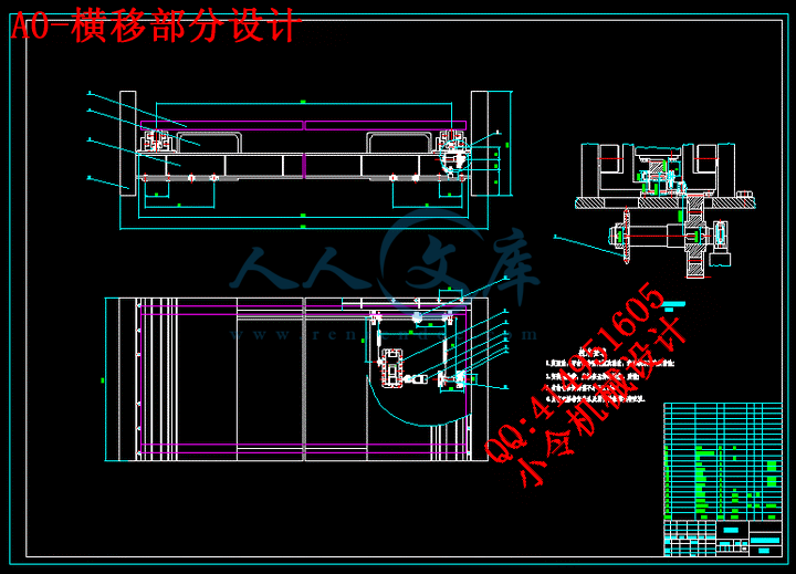
A0-横移部分设计.dwg

A0-滑叉装配图.dwg

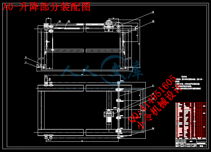
A0-升降部分装配图.dwg

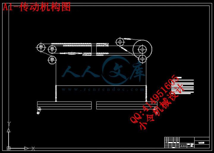
A1-传动机构图.dwg

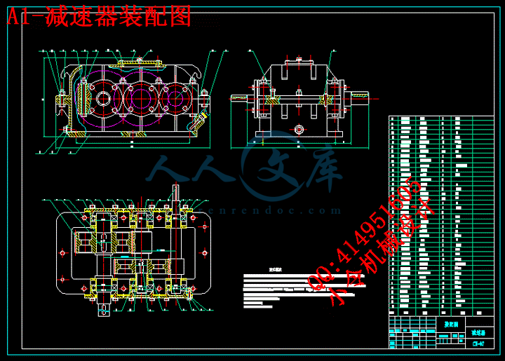
A1-减速器装配图.dwg

A1-升降架.dwg

A2-减速器大齿轮.dwg

A2-减速器低速轴.dwg

A2-链轮.dwg

A2-链轮组件图.dwg

A2-轴零件图.dwg


摘要3

Abstract4

第1章 绪论5

1.1课题的来源,目的及意义5

1.2立体车库概述5

1.3几种机械停车设备的特点及比较7

1.4 总体方案确定8

第2章  链驱动双层升降横移式车库技术参数12

2.1传动机构的组成12

2.2 传动机构的主要参数12

第3章 机械系统传动设计13

3.1传动链和链轮的选择13

3.2链的设计计算13

3.2.1设计标准13

3.2.2传动的计算14

3.3 链轮的设计计算16

3.3.1 设计链论尺寸16

3.4 滚子链的静强度计算22

3.5 链条的使用寿命计算23

3.6 链条的耐磨工作能力计算24

3.7 电动机的选择25

3.8减速器的选择26

3.9轴承的选择27

3.10轴的选择27

3.10.1 选择材料27

3.10.2 初步估算轴径27

3.10.3轴的结构设计28

3.10.4 轴上的受力分析28

3.10.5轴的强度校核30

第4章 经济分析35

4.1 机会研究35

4.1.1社会需求程度35

4.1.2 开展的基本条件35

4.2 初步可行性研究35

4.2.1 投资机会是否有希望35

4.2.2是否需要作详细可行性分析35

4.2.3 有待解决的关键性问题36

4.2.4 初步经济效益预测36

第5章  专题37

自动化立体车库管理系统37

结 论44

参考文献45

致谢46

附录1:翻译(英文)47

附录2:翻译(汉文)68


摘要

随着汽车工业和建筑业两大支柱产业的快速发展,在一些大、中城市相继出现了停车难和乱停车的现象。在解决城市城市停车难的问题中,机械式立体停车设备以其独特的优点,引起了各界的重视,得到了广泛的应用。

车辆无处停放的问题是城市的社会、经济、交通发展到一定程度产生的结果,立体停车设备的发展在国外,尤其在日本已有近30~40年的历史,无论在技术上还是在经验上均已获得了成功。我国也于90年代初开始研究开发机械立体停车设备,距今已有十年的历程。由于很多新建小区内住户与车位的配比为1:1,为了解决停车位占地面积与住户商用面积的矛盾,立体机械停车设备以其平均单车占地面积小的独特特性,已被广大用户接受。

   机械车库与传统的自然地下车库相比,在许多方面都显示出优越性。首先,机械车库具有突出的节地优势。以往的地下车库由于要留出足够的行车通道,平均一辆车就要占据40平方米的面积,而如果采用双层机械车库,可使地面的使用率提高80%-90%,如果采用地上多层(21层)立体式车库的话,50平方米的土地面积上便可存放40辆车,这可以大大地节省有限的土地资源,并节省土建开发成本。

   论文以研究工作的进展顺序为序,分章、节逐一论述了课题的来源,目的及意义,设计过程,在设计中遇到的问题与难点及其解决方法与措施。在设计过程部分,详细论述了设备总体结构设计、横移传动系统设计、提升传动系统设计、存取车结构设计、控制系统设计和安全防护设计 。  

关键词:立体停车设备 ;  传动设计;  控制系统 ; 升降机构; 安全性

Abstract

Along with the fast development of two major of pillar industry of the automobile industry and building industry, the city one after another appears to park the car the phenomenon of the difficult and disorderly parking in somely bigly,.In resolve the city city park the car difficult problem, stereoscopic parking equipments of the machine type with its special advantage, caused the value of the public, get the extensive application.

The vehicle has no a the society, economy, transportation that the problem for park is a city to develop output result to certain extent, the development of the stereoscopic parking equipments is abroad, particularly at Japan already is close to 30~40 years of history, all have already acquired the success on the technique still on the experience regardless.The our country also starts study to develop the stereoscopic parking equipments of machine at the beginning of in 90's, being apart from to already have the process of the decade now.Because a lot of set up the little inhabitant inside the area to go together with the car to compare to 1 lately:1, for solving the parking lot to cover the area and inhabitant's company to use the antinomy of the area, stereoscopic machine parking equipments with it average the bicycle covers the small special characteristic of area, have already been accept by the large customer.

   The machine garage and traditional get off the database to compare naturally, in many respect display the superiority.First, the machine garage has an advantage of outstanding stanza.Before underground garage because of toing stay to go the car passage enough, average car will occupy 40  areas of the square meters, but if a layer of adoption  machine garage, can make the utilization rate of the ground raise 80%-90%, if an up many type garages with stereoscopic layer(21 layers) of adoption, can deposit 40 cars then on 50  areas of the land of the square meters, this resources that can save the limited land consumedly, and save the soil to set up to develop the cost.

Currently the society contain a lot of mature and technical parking equipmentses for example:Ascend and descend horizontal move the type;Perpendicular and circulating type;Level circulation type;The flat surface moves the type;A  of tunnel;The perpendicular rise and fall type;Simple rise and fall.Pass the comparison and analysises to these garages  type characteristicses, I was end to choose a garage type that is the design.

   Thesis with research the progress of the work is in proper order for the preface, dividing the chapter, stanza to discuss the source of the topic one by one, purpose and meaning, the design process, problem meet in the design with a little bit difficult and it resolve method and measure.At design the process part, detailed discussed the total structure of equipments design, horizontal move to spread to move the system design and promote to spread to move the system design, access the car structure design, control the system design and safe protection design.  

Keyword: stereoscopic parking equipments;  The structure design;  Control the system;  PLC;  Safety


内容简介:
第1章 绪论1.1课题的来源,目的及意义近年来,随着经济的发展,我国的城市化水平加快和人民生活水平的提高,汽车的数量不断增加。中国的汽车市场2006年新车销量达721万辆,与上一年相比增加了25%。轿车的增长幅度尤为明显,同比增长37%,达到380万辆,三年间增加了近一倍。根据权威估计,2008年中国汽车市场的销量将达1000万辆。但与此同时,汽车停车场地的增长却不能与之同步,汽车泊位与汽车数量严重比例失调,由此带来停车难,违章停车,停车管理困难等一系列问题。链驱动双层升降横移式停车设备又名立体车库,它占地空间小,并且可以最大限度的利用空间,安全方便,是解决城市用地紧张,缓解停车难的一个有效手段。国家记委已明确机械立体停车设备及城市立体停车场为国家重点支持的产业。1998年1月1日起执行的国家记委6号令把机械式立体车库和立体停车场列入“国家重点鼓励发展的产业,产品和技术”。国家海关总署对机械式停车产品规定“国内投资项目给予免征进口税”。上述措施为我国立体车库产业的成长提供了良好的条件,也为我国解决城市停车问题提供了机会。可以预见:立体车库具有广阔的市场前景。研究的目的就是开发一套实用,安全有效的链驱动双层升降横移式立体车库停车设备,并进行相应的扩展研究。本项目的研究与开发,为21世纪初期的城市交通系统提供实用的,具有自主知识产权,国产化城市停车技术和装备,对缓解城市用地紧张,解决城市停车难的问题具有重要意义。1.2立体车库概述车辆无处停放的问题是城市的社会、经济、交通发展到一定程度产生的结果,立体停车设备的发展在国外,尤其在日本已有近3040年的历史,无论在技术上还是在经验上均已获得了成功。我国也于90年代初开始研究开发机械立体停车设备,距今已有十年的历程。由于很多新建小区内住户与车位的配比为1:1,为了解决停车位占地面积与住户商用面积的矛盾,链驱动双层升降横移式立体车库停车设备以其平均单车占地面积小的独特特性,已被广大用户接受。链驱动双层升降横移式车库与传统的自然地下车库相比,在许多方面都显示出优越性。首先,机械车库具有突出的节地优势。以往的地下车库由于要留出足够的行车通道,平均一辆车就要占据40平方米的面积,而如果采用双层机械车库,可使地面的使用率提高80-90,如果采用地上多层(21层)立体式车库的话50平方米的土地面积上便可存放40辆车,这可以大大地节省有限的土地资源,并节省土建开发成本。 链驱动双层升降横移式车库与地下车库相比可更加有效地保证人身和车辆的安全,人在车库内或车不停准位置,由电子控制的整个设备便不会运转。应该说,链驱动双层升降横移式车库从管理上可以做到彻底的人车分流。 在地下车库中采用机械存车,还可以免除采暖通风设施,因此,运行中的耗电量比工人管理的地下车库低得多。链驱动双层升降横移式车库一般不做成套系统,而是以单台集装而成。这样可以充分发挥其用地少、可化整为零的优势,在住宅区的每个组团中或每栋楼下都可以随机设立机械停车楼。这对眼下车库短缺的小区解决停车难的问题提供了方便条件。在中华人民共和国机械行业标准 JB/T 8713-1998 :机械式停车设备类别,形式,基本参数要目中,对机械式停车设备进行了划分,其类别代号如下:升降横移类,代号为SH,是指通过设备的垂直升降和水平横移进行移动,实现车辆存取功能的停车设备。垂直循环类,代号为CX,是指通过搬运器在垂直平面内做连续的循环移动,来实现车辆存取功能的停车设备。水平循环类,代号为SX,是指搬运器在水平平面内排列成2列或2列以上连续循环列尖转换移动,实现车辆存取功能的停车设备。多层循环类,代号为DX,是指车辆搬运器在垂直平面内排成2层或2层以上做连续移动,两端有升降机构进行循环层间转换移动,实现车辆存取的停车设备。平面移动类,代号为PY,是指存车位与搬运器在同一水平面内,通过搬运器在水平面内做往复移动,实现车辆存取功能的停车设备。巷道堆垛类,代号为XD,是指存车位在巷道一边或两边多层布置,通过搬运器在巷道内做水平,垂直或水平垂直复合运动,实现车辆的存取功能的停车设备。垂直升降类,代号为CS,是指停车位分布在井道周围,通过升降搬运器在专用升降通道内做升降移动,时间车辆存取功能的停车设备。简易升降类,代号为JS,是指通过单一搬运器的升降,俯仰或二三层搬运器的整体升降,俯仰,实现车辆二三层车辆存取功能的停车设备。汽车升降机类代号为QS;是指搬运器运载车辆(或同时运载驾驶员)垂直升降运行进行多层平层对位,从搬运器到存车位需要驾驶员驾车入位,实现车辆存取功能的停车设备。 巷道堆垛式立体车库采用堆垛机作为存取车辆的工具,所有车辆均由堆垛机进行存取,因此对堆垛机的技术要求较高,单台堆垛机成本较高,所以巷道堆垛式立体车库适用于车位数需要较多的客户使用。巷道堆垛式立体车库设备是20世纪60年代后欧洲根据自动化立体车库原理设计的一种专门用于停放小型汽车的停车设备。该种车库设备采用先进的计算机控制,是一种集机、光、电、自动控制为一体的全自动化立体全封闭车库,存车安全等特点。该类车库主要适应大型密集式存车。1.3几种机械停车设备的特点及比较(一) 升降横移式升降横移式立体车库采用模块化设计,每单元可设计成两层、三层、四层、五层、半地下等多种形式,车位数从几个到上百个。此立体车库适用于地面及地下停车场,配置灵活,造价较低。1. 产品特点:1) 节省占地,配置灵活,建设周期短。2) 价格低,消防、外装修、土建地基等投资少。3) 可采用自动控制,构造简单,安全可靠。4) 存取车迅速,等候时间短。5) 运行平稳,工作噪声低。6) 适用于商业、机关、住宅小区配套停车场的使用。(二) 巷道堆垛式巷道堆垛式立体车库采用堆垛机作为存取车辆的工具,所有车辆均由堆垛机进行存取,因此对堆垛机的技术要求较高,单台堆垛机成本较高,所以巷道堆垛式立体车库适用于车位数需要较多的客户使用。(三)垂直提升式垂直提升式立体车库类似于电梯的工作原理,在提升机的两侧布置车位,一般地面需一个汽车旋转台,可省去司机调头。垂直提升式立体车库一般高度较高(几十米),对设备的安全性,加工安装精度等要求都很高,因此造价较高,但占地却最小。(四) 垂直循环式产品特点:1) 占地少,两个泊位面积可停610辆车。2) 外装修可只加顶棚,消防可利用消防栓。3) 价格低,地基、外装修、消防等投资少,建设周期短。4) 可采用自动控制,运行安全可靠。基于上述比较,根据需要现选择链驱动双层升降横移式车库进行设计。1.4 总体方案确定由于我设计的链驱动双层升降横移式车库,所以首先应确定用哪种方式升降,如可采用升降机式、电梯式。其次,对于传动系统(包括链传动的链与棘轮的设计、钢丝吊动的滑轮和钢丝绳的设计、电机型号的选用)、载车板等机械部分的绘图设计和控制系统的简单设计,要确定传动的方式,如钢丝绳,链条等;初步拟定方案如下:方案1:一、根据轿车尺寸确定每个车位载车板的长度宽度。设计载车板的形式,计算校核载车板的力学性能。二、根据对传动结构的分析和受力的分析选择采用电梯式升降。选择滑轮,确定其尺寸。确定钢丝绳的材料、直径。对上述部件进行力学计算,校核。三、使用转向盘,当车降下时已转换方向。转向盘可通过齿轮或者涡轮蜗杆实现转向。四、确定制动方案。选择电磁接触阀。五、载荷均匀分布,机械效率高。六、结构简单,工作可靠,拆装维修方便。七、考虑安全防护设计。八、考虑环保设计。九、经济性考虑。方案2:一、根据轿车尺寸确定每个车位载车板的长度宽度。设计载车板的形式,计算校核载车板的力学性能。二、根据传动结构的分析和受力的分析选择采用升降机式的升降机构。选择链轮和链,确定其尺寸规格。然后对其校核。三、不用转向,故不用转向盘。结构简单,工作可靠,拆装维修方便四、确定制动方案。选择电磁接触阀。五、载荷均匀分布,机械效率高。六、考虑安全防护设计。七、考虑环保设计。八、经济性方案设计。综合以上两种设计方案,第二种方案比较适合本设计。整个机构的传动机构采用链传动,在上面放置两条循环链,两条链通过一条通轴连接,而通轴上的链轮由与减速器相连链带动,实现转动,从而带动两条循环链同步转动,这样就保证了传动的平稳性。而第一种方案中,如果用钢丝绳传动也可实现机构的传动,但是如果要实现第一种方案一样的功能,传动过程显得就要麻烦一些。因为要是实现同步转动,必须选择链与钢丝绳同时使用才能达到同步传动的效果。本设计的传动特点是:自动化程度高,快速处理,连续出入库,停车效率高。组合式框架设计,保证了产品一致性, 安装拆卸非常方便。设有多重安全防护措施,确保人车安全。操作简便,既可集中管理,又可由客户自己操作。电机及所用电器元件采用进口名牌产品。不排出汽车废气,清洁环保。1.5 移动方案的比较机械式立体停车库有许多种类型,根据其工作原理可分为:升降横移式;水平循环式; 平面移动式等等。采用以载车板升降或横移存取车辆的机械式停车设备叫做升降横移式立 体停车库,由于升降横移式停车库的类型比较多,规模可大可小,对场地的适应性强,因 此采用这一类型的停车库十分的普遍。升降横移式立体停车库每个车位均有载车板,所需存取车辆的载车板通过升降横移运动到达地面层,驾驶员进入车库,存取车辆,完成存取过程。停泊在这类车库内地面的车 只作横移,不必升降,上层车位或下层车位需要通过中间层横移出空位,将载车板升或降 到地面层,驾驶员才可以进入车库内将汽车开进或开出车库。升降横移式立体停车库的布 置型式主要有两种:半地下布置型式和地上布置型式本设计是双层六位五车的小型立体车库,多用于居民小区,其简图如下所示:456123图2-1移动方案(1):将1号车位作为定位,2,3 号车位可以直接提取车。 在存取 4 号车时,将 4 号位降到 1 号位上,进行存取车。在存取 5 号车时,将 2 号位移动到 1 号为上,5 号位降到 2 号位上,进行存取车。 在存取 6 号车时,将 2 号位移动到 1 号位上,3 号位移动到 2 号位上,5 降到 3 号位进行存取车。移动方案(2):可将3号车位作为定位,其存取方式和方案(1)相同,故不再做表述。移动方案(3):将号2车位作为定位,1,3 号车位可以直接进行存取车。在存取 4 号车时,将 1 号车位移动到 2 号车位上,4 号车位降到 1 位进行存取车。 在存取 5 号车时,将 5 号车位降到 2 位上,进行存取车。在存取 6 号车时,将 3 移动到 2 位上,6 降到 3 号车位上,进行存取车。综上所述,可以知道方案(3)最快捷,所以本设计采用方案(3)作为车库整体移动的方案。第2章 链驱动双层升降横移式车库技术参数2.1传动机构的组成本传动机构如下图,由循环链,两条升降链,和14个链轮组成,图中显示的是对称结构的一部分,两部分由端部的一通轴连接。升降部分主要是用于第二层车辆的存放,在第一层将车存放在载车板上,通过两条升降链将车升到二层,然后在经过PLC控制,由循环链来控制轿车放在哪个车位。2.2 传动机构的主要参数技 术 性 能 参 数名称:链驱动双层升降横移式车库放车辆数:5辆使用车尺寸:4700*1700*1550驱动:5.5kw电动机速度:6m/min车重:1600KG适用车型:小型轿车控制方式:伺服定位控制管理方式:专人管理方式操作方式:触摸屏操作实现方式:上层实现链驱动形式升降存取车辆,下层实现横移存取车辆第3章 机械系统传动设计3.1传动链和链轮的选择起重链有环行焊接链和片式关节链。焊接链与钢丝绳相比,优点是挠性大,链轮片齿数可以很少,因而直径小,结构紧凑,其缺点是对冲击的敏感性大,突然破断的可能性大,磨损也较快。另外,不能用于高速,通常速度小于0.1米/秒(用于星轮),速度小于1米/秒,用于光轮卷筒。片式关节链的优点:挠性较焊接链更好,可靠性高,运动较平稳。缺点:有方向性,横向无挠性,比钢丝绳重,与焊接链差不多,成本高,对灰尘和锈蚀胶敏感。起重链用于起重量小,起升高度小,起升速度低的起重机械。为了携带和拆卸方便,链条的端部链节用可拆卸链环。片式关节链是由薄刚片以销轴铰接而成的一种链条。焊接链与片式关节链选择计算方法相同。根据最大工作载荷及安全系数计算链条的破坏载荷 (N) Fmax链条最大工作载荷(N)S安全系数(按手册28.175选取)选择片式关节链中的传动用短节距精密磙子链结构和特点:由外链节和内链节铰接而成。销轴和外链板、套筒和内链板为静配合;销轴和套筒为动配合;磙子空套在套筒上,可以自由转动,以减少啮合时的摩擦和和磨损,并可以缓和冲击,故选择单排短节距磙子链。3.2链的设计计算3.2.1设计标准准GB/T1815002000滚子链传动选择指导是链传动设计选择标准。此标准等同采用ISO10823。3.2.2传动的计算1. 链轮齿数小链轮齿数 取=25,传动比i=2.5大链轮齿数 =i=2.525=62.5 取622. 实际传动比i=2.483. 链轮转速初选小链轮线速度=0.1m/s,估选小链轮直径d=160mm,则大链轮直径D=id=2.48160=396mm由大链轮和小链轮在同一轴上,故大链轮上的线速度=0.12.48=0.248m/s,则与电机相连的小链轮的线速度=0.248m/s则其转速为=30m/s则大链轮转速为=12r/min4. 修正功率小链轮传递功率为P=2.4kW故=2.41.41=3.36kW式中参数:查机械设计手册表14.2-4,工况系数=1.4,主动链轮齿数系数=1,5. 链条节距P11摘要3Abstract4第1章 绪论51.1课题的来源,目的及意义51.2立体车库概述51.3几种机械停车设备的特点及比较71.4 总体方案确定8第2章 链驱动双层升降横移式车库技术参数122.1传动机构的组成122.2 传动机构的主要参数12第3章 机械系统传动设计133.1传动链和链轮的选择133.2链的设计计算133.2.1设计标准133.2.2传动的计算143.3 链轮的设计计算163.3.1 设计链论尺寸163.4 滚子链的静强度计算223.5 链条的使用寿命计算233.6 链条的耐磨工作能力计算243.7 电动机的选择253.8减速器的选择263.9轴承的选择273.10轴的选择273.10.1 选择材料273.10.2 初步估算轴径273.10.3轴的结构设计283.10.4 轴上的受力分析283.10.5轴的强度校核30第4章 经济分析354.1 机会研究354.1.1社会需求程度354.1.2 开展的基本条件354.2 初步可行性研究354.2.1 投资机会是否有希望354.2.2是否需要作详细可行性分析354.2.3 有待解决的关键性问题364.2.4 初步经济效益预测36第5章 专题37自动化立体车库管理系统37结 论44参考文献45致谢46附录1:翻译(英文)47附录2:翻译(汉文)682摘要随着汽车工业和建筑业两大支柱产业的快速发展,在一些大、中城市相继出现了停车难和乱停车的现象。在解决城市城市停车难的问题中,机械式立体停车设备以其独特的优点,引起了各界的重视,得到了广泛的应用。车辆无处停放的问题是城市的社会、经济、交通发展到一定程度产生的结果,立体停车设备的发展在国外,尤其在日本已有近3040年的历史,无论在技术上还是在经验上均已获得了成功。我国也于90年代初开始研究开发机械立体停车设备,距今已有十年的历程。由于很多新建小区内住户与车位的配比为1:1,为了解决停车位占地面积与住户商用面积的矛盾,立体机械停车设备以其平均单车占地面积小的独特特性,已被广大用户接受。 机械车库与传统的自然地下车库相比,在许多方面都显示出优越性。首先,机械车库具有突出的节地优势。以往的地下车库由于要留出足够的行车通道,平均一辆车就要占据40平方米的面积,而如果采用双层机械车库,可使地面的使用率提高80-90,如果采用地上多层(21层)立体式车库的话,50平方米的土地面积上便可存放40辆车,这可以大大地节省有限的土地资源,并节省土建开发成本。 论文以研究工作的进展顺序为序,分章、节逐一论述了课题的来源,目的及意义,设计过程,在设计中遇到的问题与难点及其解决方法与措施。在设计过程部分,详细论述了设备总体结构设计、横移传动系统设计、提升传动系统设计、存取车结构设计、控制系统设计和安全防护设计 。 关键词:立体停车设备 ; 传动设计; 控制系统 ; 升降机构; 安全性AbstractAlong with the fast development of two major of pillar industry of the automobile industry and building industry, the city one after another appears to park the car the phenomenon of the difficult and disorderly parking in somely bigly,.In resolve the city city park the car difficult problem, stereoscopic parking equipments of the machine type with its special advantage, caused the value of the public, get the extensive application.The vehicle has no a the society, economy, transportation that the problem for park is a city to develop output result to certain extent, the development of the stereoscopic parking equipments is abroad, particularly at Japan already is close to 3040 years of history, all have already acquired the success on the technique still on the experience regardless.The our country also starts study to develop the stereoscopic parking equipments of machine at the beginning of in 90s, being apart from to already have the process of the decade now.Because a lot of set up the little inhabitant inside the area to go together with the car to compare to 1 lately:1, for solving the parking lot to cover the area and inhabitants company to use the antinomy of the area, stereoscopic machine parking equipments with it average the bicycle covers the small special characteristic of area, have already been accept by the large customer. The machine garage and traditional get off the database to compare naturally, in many respect display the superiority.First, the machine garage has an advantage of outstanding stanza.Before underground garage because of toing stay to go the car passage enough, average car will occupy 40 areas of the square meters, but if a layer of adoption machine garage, can make the utilization rate of the ground raise 80%-90%, if an up many type garages with stereoscopic layer(21 layers) of adoption, can deposit 40 cars then on 50 areas of the land of the square meters, this resources that can save the limited land consumedly, and save the soil to set up to develop the cost.Currently the society contain a lot of mature and technical parking equipmentses for example:Ascend and descend horizontal move the type;Perpendicular and circulating type;Level circulation type;The flat surface moves the type;A of tunnel;The perpendicular rise and fall type;Simple rise and fall.Pass the comparison and analysises to these garages type characteristicses, I was end to choose a garage type that is the design. Thesis with research the progress of the work is in proper order for the preface, dividing the chapter, stanza to discuss the source of the topic one by one, purpose and meaning, the design process, problem meet in the design with a little bit difficult and it resolve method and measure.At design the process part, detailed discussed the total structure of equipments design, horizontal move to spread to move the system design and promote to spread to move the system design, access the car structure design, control the system design and safe protection design. Keyword: stereoscopic parking equipments; The structure design; Control the system; PLC; Safety5附录1:翻译(英文)Modeling and specifcations of dynamic agents in fractal manufacturing systemsKwangyeol Ryua, Youngjun Sonb, Mooyoung Junga,*a Department of Industrial Engineering, Pohang University of Science and Technology, Pohang, South Korea Systems and Industrial Engineering Department, The University of Arizona, Tucson, AZ, USA b Received 9 September 2002; accepted 16 April 2003 Abstract In order to respond to a rapidly changing manufacturing environment and market, manufacturing systems must be flexible, adaptable, and reusable. The fractal manufacturing system (FrMS) is one of the new manufacturing paradigms that address the need for these characteristics. The FrMS is comprised of a number of basic components, each of which consists of five functional modules: (1) an observer, (2) an analyzer, (3) an organizer, (4) a resolver, and (5) a reporter. Each of these modules, using agent technology, autonomously cooperates and negotiates with others while processing its own jobs. The resulting architecture has a high degree of self-similarity, one of the main characteristics of a fractal. Despite the many conceptual advantages of the FrMS, it has not been successfully elaborated and implemented to date because of the difficulties involved in doing so. In this paper, the static functions and dynamic activities of each agent are modeled using the unified modeling language (UML). Then, relationships among agents, working mechanisms of each agent, and several fractal-specific characteristics (selfsimilarity, self-organization, and goal-orientation) are modeled using the UML. Then, a method for dealing with several types of information such as products, orders, and resources in the FrMS is presented. Finally, a preliminary prototype for the FrMS using AgletsTM is presented. # 2003 Elsevier B.V. All rights reserved. Keywords: Fractal manufacturing system (FrMS); Agent technology; UML; ModelingAbbreviations: FrMS, fractal manufacturing system; BFU, basic fractal unit; DRP, dynamic restructuring process; UML, uni?ed modeling language; HMS, holonic manufacturing system; BMS, bionic/biological manufacturing system; CNP, contract net protocol; MANPro, mobile agent-based negotiation process; NMA, network monitoring agent; EMA, equipment monitoring agent; SEA, schedule evaluation agent; DRA, dispatching-rule rating agent; RSA, real-time simulation agent; SGA, schedule generation agent; GFA, goal formation agent; TGA, task governing agent; NEA, negotiation agent; KDA, knowledge database agent; DMA, decision-making agent; FSM, fractal status manager; FAM, fractal address manager; REA, restructuring agent; NCA, network command agent; ECA, equipment command agent; STA, system agent; NTA, network agent; MP, material processor; MH, material handler; MT, material transporter; BS, buffer storage; MRP, material removal processor; MFP, material forming processor; MIP, material inspection processor; PD, passive device; FMH, ?xed material handler; MMH, movable material handler; FMT, fixed material transporter; MMT, movable material transporter; ABS, active buffer storage; PBS, passive buffer storage E-mail address: myjungpostech.ac.kr (M. Jung).* Corresponding author. Tel.: t82-54-279-2191; fax: t82-54-279-5998.0166-3615/$ see front matter # 2003 Elsevier B.V. All rights reserved. doi:10.1016/S0166-3615(03)00099-X 1. IntroductionFacing intensified competition in a growing global market, manufacturing enterprises have been reengineering their production systems to achieve computer integrated manufacturing (CIM). Major goals of CIM include, but are not necessarily limited to, lowering manufacturing costs, rapidly responding to changing customer demands, shortening lead times, and increasing the quality of products 13. However, the development of a CIM system is an incredibly complex activity, and the evolution to CIM has been slower than expected 4,5. This can be directly attributed to high software development and maintenance costs. Therefore, in order to achieve a competitive advantage in the turbulent global market, the manufacturing enterprise must change manufacturing processes from all angles including ordering, product design, process planning, production, sales, etc. As a control model for implementing CIM systems, hierarchical decomposition of shop floor activities has been commonly used in the shop floor control system (SFCS), the central part of a CIM system 2. Generally, a central database provides a global view of the overall system, and controllers generate schedules and execute them. Hierarchical control is easy to understand and is less redundant than other distributed control architectures such as heterarchical control. However, it has a crucial weak point, which is that a small change in one level may significantly and adversely affect the other levels in the hierarchy. Therefore, it is normally said that hierarchical control of CIM systems is much more suitable for production in a steady environment than in a dynamically changing environment because it is so diffcult to apply control hierarchy changes immediately to the equipment. Furthermore, it is diffcult to meet dynamically changing customer requirements because the hierarchical control architecture is not flexible enough to handle the reconfiguration of the shop. Therefore, the manufacturing system of tomorrow should be flexible, highly reconfigurable, and easily adaptable to the dynamic environment. Furthermore, it should be an intelligent, autonomous, and distributed system composed of independent functional modules. To cope with these requirements, new manufacturing paradigms such as a bionic/biological manufacturing system (BMS) 6,7, a holonic manufacturing system (HMS) 8,9, and a fractal manufacturing system (FrMS) 1013 have been proposed. Tharumarajahet al. 14 provide a comprehensive comparison among a BMS, a HMS, and an FrMS in terms of design and operational features. An FrMS is a new manufacturing concept derived from the fractal factory introduced by Warnecke 13. It is based on the concept of autonomously cooperating multi-agents referred to as fractals. The basic component of the FrMS, referred to as a basic fractal unit (BFU), consists of five functional modules including an observer, an analyzer, a resolver, an organizer, and a reporter 10,11. The fractal architectural model represents a hierarchical structure built from the elements of a BFU, and the design of a basic unit incorporates a set of pertinent attributes that can fully represent any level in the hierarchy 12. In other words, the term fractal can represent an entire manufacturing shop at the highest level or a physical machine at the bottom-level. Each BFU provides services according to an individual-level goal and acts independently while attempting to achieve the shoplevel goal. An FrMS has many advantages for a distributed and dynamic manufacturing environment. Automatic reconfiguration of a system through a dynamic restructuring process (DRP) is the most distinctive characteristic of the FrMS. In this paper, the scope of the reconfiguration does not include reconfigurable hardware 15 and external layout design. Rather, it focuses on the interior structure of software components that can be reorganized with software manipulations. The reconfiguration or restructuring in this paper considers both dynamic clustering of the agents and construction/destruction/cloning of agents, which affect the number of agents in the system. The function of a fractal is not specifically designated at the time of its first installation in the FrMS. The reconfiguration addressed in this paper also includes situations where the agents enrollments are changed, meaning that the agents are assigned a new goal and new jobs, but their composition does not change. This paper focuses on formal modeling of agents and fractal-specific characteristics that will provide a foundation for the development of the FrMS. Because associated difficulties have, to date, prevented a fractal-based system from being embodied, it is necessary to first explicitly define a concept, mechanisms, and characteristics.The objective of this paper, therefore, is to clearly define and model fractal-specifc characteristics for a manufacturing system to have such characteristics. In order to develop the agents, interand intra-fractal activities are first clarified. Then, dynamic activities for each agent and relationships between agents are modeled. In order to more fully develop the FrMS, several fractal-specific characteristics are also modeled. To support embodiment of modeled characteristics, a method for dealing with information about products, orders, and resources in the FrMS is investigated. Through this research, mechanisms of agents and characteristics of the FrMS can be described with simple diagrams that make the system easier to understand. The work contained in this paper extends the FrMS from previous papers by emphasizing and detailing its characteristics. The activities of agents are specified using activity models so that the agents can use the activity models to forecast their next activities at run-time. The rest of this paper is organized as follows: Section 2 describes functions and dynamic activities of agents using functional and activity models of unified modeling language (UML). In Section 3, inter- and intra-fractal activities are specified. Several fractal-specific characteristics are described using UML models in Section 4. Section 5 describes a method for dealing with information about products and resources in the FrMS. Section 6 concludes the paper.2. Agent-based fractal manufacturing system (FrMS) 2.1. Background of an FrMS An overview of the FrMS is depicted in Fig. 1. Every controller at every level in the system has a selfsimilar functional structure composed of functional modules. In addition, each of these modules, regardless of its hierarchical level, consists of a set of agents. After the initial setup of a system, the configuration of the system may need to be reorganized in response to unexpected events such as machine breakdown. The system will also need to be reconfigured when the set of parts to be produced in the system changes due to a change in customer needs. In these cases, fractals in the FrMS autonomously and dynamically change their structure, via the actions of agents for the appropriate working mechanisms of the fractals. Fig. 1 shows two facility layouts and the corresponding compositions of fractals before and after the restructuring process. When a machine (M) and a robot (R3) are added to the system, fractals reorganize their interior configurations with the mechanism of dynamic restructuring process in a way that the system continues to work with greatest efficiency. A fractal consists of five functional modules illustrated with their relationships in Fig. 2. The functions of each module can be defined depending upon the application domain.Fig. 1. Reorganization of the system using a dynamic restructuring process in the FrMS.However, when the target domain is determined, the main functions of each module will be consistent throughout the system. For example, the function of a resolver may be different depending upon whether it is defined for controlling a manufacturing system or for managing supply chains. However, the main function of a resolver in a manufacturing system is similar to other resolvers in that system regardless of their level in the hierarchy. A bottom-level fractal has similar functions to those of a conventional equipment controller in a SFCS. A fractal, which is directly connected to equipment (e.g. machine, robot, etc.), receives sensory signals of equipment and returns messages or commands. The function of an observer is to monitor the state of the unit, to receive messages and information from outer fractals, and toFig. 2. Functional modules and relationships of a fractal in an FrMS.transmit composite information to correspondent fractals. The function of an analyzer is to analyze alternative job profiles with status information, to rate dispatching rules, and to simulate analyzed job profiles in real-time. The analyzer finally reports results to the resolver so that the resolver can use them to make decisions. A resolver plays the most important role in a fractal, generating job profiles, goal-formation processes, and decision-making processes. During goal-formation processes, the resolver may employ a variety of numerical optimization or heuristic techniques to optimize the fractals goal. If necessary, the resolver executes negotiations, cooperation, and coordination among fractals. The function of an organizer is to manage the fractal status and fractal addresses, particularly for dynamic restructuring processes. The organizer may use numerical optimization techniques to find an optimal configuration while reconfiguring fractals. The fractal status is used to select the best job profile among several alternatives, and the fractal address is used to find the physical address of the fractal (e.g. machine_name, port_number, etc.) on the network. The function of a reporter is to report results from all processes in a fractal to others. In the case of a bottom-level controller, the fractal is similar to a traditional equipment controller. Therefore, most of its messages are commands for controlling the hardware.2.2. Agents in an FrMS Agent technology has been widely used for various applications including information filtering and gathering 16, knowledge management 17, supply chain management 18, manufacturing architecture, system and design 1921. While the features and characteristics of an agent vary depending on the application, some common features found across different applications are as follows: Autonomy: capability of controlling and acting for itself in order to achieve goals. Mobility: capability of migrating its location to other places (an agent with mobility is called a mobile agent, otherwise known as a software or stationary agent). Intelligence: capability of learning and solving problems. Cooperativeness: capability of helping others if requested and accepting helps from others. Adaptability: capability of being effectively used at various domains. Reliability: capability of dealing with unknown situations (disturbances) and continuing actions if committed, etc. The mobility of agents is a useful feature in a distributed and dynamic system. A mobile agent is not bound to the system where it begins execution. It can travel freely among the controllers in a network and transport itself from one system in a network to another. The following are some advantages of the use of mobile agents in a system 22: (1) it reduces the network load, (2) it overcomes network latency, (3) it encapsulates protocols, (4) it executes asynchronously and autonomously, (5) it adapts dynamically, (6) it is naturally heterogeneous, and (7) it is robust and faulttolerant. The types and functions of agents that implement functional modules of an FrMS have been brie?y described, and their initial development has been published in the earlier literature 11. This paper enhances and re?nes the previously defined types and functions of agents so that they can perform functions of fractals successfully in the system. The names, types, and functions of agents in the FrMS are described as follows. The terms -M and -S written after the abbreviated name of each agent represent mobile agents and software agents, respectively. 2.2.1. Agents for an observerNetwork monitoring agent (NMA-S): It monitors messages from other fractals through TCP/IP. It receives messages from the upper/same/lower-level fractals, such as requests for negotiations, negotiation replies, job orders, status information, etc. The NMA delivers those messages to the resolver or the analyzer. Equipment monitoring agent (EMA-S): It monitors messages directly coming from equipment through a serial communication protocol such as RS232/ 422. Information on the status of equipment including signals indicating the start and completion of jobs are detected by the EMA. However, the fractal need not directly control equipment if it is not included in a bottom-level.2.2.2. Agents for an analyzer Schedule evaluation agent (SEA-S): A SEA evaluates job profiles generated by the resolver. It helps the resolver to select the best job profile with respect to the current situation of the fractal. Dispatching-rule rating agent (DRA-S): It chooses the best dispatching rule for achieving its goals among several rules, such as shortest processing time (SPT), earliest due date (EDD), and so on. Real-time simulation agent (RSA-S): It performs real-time simulations in the on-line state with the results of the analyzed job profiles and the best dispatching rule. The RSA reports the results of simulations to the resolver.2.2.3. Agents for a resolver Schedule generation agent (SGA-M): It generates operational commands or alternative job profiles for achieving the fractals goals. After evaluation and analysis of alternatives in the analyzer, the SGA selects the best job profile. It must have mobility in order to use SEA, DRA, and RSA in the analyzer.Goal formation agent (GFA-S): It modifies incomplete goals delivered from the upper-level fractal, and tries to make the goals complete by considering the current situation of the fractal. GFA divides the goal of the fractal into several sub-goals, and sends them to the sub-fractals. Task governing agent (TGA-S): A TGA generates tasks from the best job profile and its goals. It also performs tasks after arriving at the target fractal. When it finishes performing tasks, it sends acknowledgement to its sender. Negotiation agent (NEA-M): It moves to other fractals to deliver negotiation messages or to gather negotiation replies created by participating agents. It filters out unreasonable replies by a pre-evaluation process and brings the rest back to the resolver. Knowledge database agent (KDA-M): KDA invokes knowledge data from the knowledge database to make decisions. It accumulates new knowledge or updates the existing knowledge. Decision-making agent (DMA-S): It performs several operations during the decision-making processes. A DMA creates NEAs to negotiate with other fractals and KDAs to use the knowledge database. After making decisions, the DMA generates several TGAs. Further, the DMA provides a context to agents for negotiation.2.2.4. Agents for an organizerFractal status manager (FSM-S): The FSM collects and manages the information on the status of fractals that is used for analyzing job profiles in the analyzer. It also makes negotiation replies to the status requests from other fractals. Fractal address manager (FAM-S): The FAM manages information about the addresses of fractals in lower levels and at the same level. A fractal address is the fractals physical address on the network, such as an IP address. The reporter uses a fractals address to confirm the destination of tasks and messages. Restructuring agent (REA-M): It performs several operations related to dynamic restructuring processes, such as BFU generation, BFU deletion, and the evaluation of the fractals performance. The performance of a fractal is its utilization, e.g. total number of processed jobs or the portion of processing time within total time, etc. If the REA decides that a fractal needs to be restructured, it gathers information about fractal and network addresses, and fractal status. It moves to the DMA and lets it generate a series of jobs for a restructuring process. The cloning mechanism is used to create a new BFU. After creation, the REA tells the FAM to update the addresses of other fractals.2.2.5. Agents for a reporter Network command agent (NCA-M): All tasks or messages are delivered to other fractals by the NCA. NCA gets the network address of the destination from the FAM and notifies the TGAs and NEAs of it before starting to migrate to other places to comply with the traveling list. Equipment command agent (ECA-S): When ECA gets tasks for controlling equipment from a TGA, it specifies or divides the tasks into several commands that can be accepted and performed by the equipment. Then it sends the machine commands to the equipment. Like the EMA, the ECA is not needed for a fractal at the bottom-level. In addition to the five functional agents, several other agents are needed for components to function like fractals. 2.2.6. Miscellaneous agents System agent (STA-S): It manages device hardware and basic operating systems of physical controllers. It maintains the specifications of controllers so that REA can find the proper specification for a new controller which has to be set up as a fractal among available candidates during dynamic restructuring processes. It can also help to copy agents by doing preparation work such as making directories or installing device drivers by giving notice to an installer about software for equipment. Network agent (NTA-S): It manages the network addresses of the unassigned controllers in the system. If the system needs more controllers during the restructuring process, the REA confirms the information about the unassigned controllers from the NTA before cloning agents.When a fractal changes the information about the unassigned controllers, it must notify other fractals so that they can update their information. 2.3. Agent modeling with UML To make system architecture manageable and understandable, the artifacts of a system-intensive process can be expressed, specified, visualized, constructed, and documented. In recent years, a unified modeling language has emerged from earlier methods for analysis and design of object-oriented (OO) systems. In 1997, UML became recognized and accepted as a potential notation standard by Object Management Group (OMG) for modeling multiple perspectives of various systems 23. UML is a simple, expressive, extensible, and visual modeling language 24. UML is based on the object-oriented paradigm, and enables the extraction of architecturally significant elements of a model with respect to different viewpoints, independent of the systems scale. It is mainly used to develop control software because many UML tools support the automatic generation of programming code from UML models. In this paper, modeling of the FrMS with UML is based on the implementation of an agent-based system. 2.3.1. Why UML? UML provides several advantageous features for modeling a system 25. First, it enables modeling of systems using OO concepts because its semantics come from Booch, object modeling technique (OMT), and object-oriented software engineering (OOSE). In particular, the use of a packagesupporting OO concepts allows users to refine models iteratively. Second, it uni?es several modeling perspectives, enabling modeling of different kinds of systems (business versus software) and different development phases (requirements analysis, design, and implementation). Various kinds of models from different perspectives can be easily managed with one ?le. Third, many UML tools automatically generate skeleton source code from a model. For example, Rational RoseTM supports code generation in C/Ctt, Visual Basic, Java/J2EE, Ada 83/95. It also supports eXtensible Markup Language_Data Type Definition (XML_DTD) and Common Object Request Broker Architecture (CORBA). Fourth, UML supports the use of a formal constraint language called Object Constraint Language (OCL) to specify constraints and other expressions attached to the models. OCL is a formal language that remains easy to read and write for adding unambiguous constraints to a model. The last advantage of UML is that it supports Model Driven Architecture (MDA) which is accepted as a standard by OMG. MDA addresses the complete life cycle of designing, deploying, integrating, and managing applications as well as data using open standards. It also provides an open, vendor-neutral approach to the challenge of interoperability. 2.3.2. UML models for an FrMS and agents The fractal agents are modeled by using a class diagram as shown in Fig. 3. A class diagram describes the types of objects that are used within an objectoriented system, and de?nes the types of relationships between them. Attributes and operations of each class are used to de?ne the types of objects and the constraints between them. Four types of relationships available in the class model of UML are association, aggregation, generalization, and dependency (instantiates). The class diagram in Fig. 3 uses only associations (uni- and bi-directional) and dependency. An association relationship, the most general relationship, provides a pathway for the communication between model components including a class and an interface. A dependency is a relationship between two classes in which a change to one class will affect the other class. Stereotypes are usually used in UML models for representing the sub-classification of model elements. In addition to the predefined stereotypes, users can define customized stereotypes. Some classes in Fig. 3 have a stereotype called an entity, which is represented as an icon (circle with underbar). Also, some other stereotypes are used such as uses, creates, and supports and so on for the clari?cation of the associations between the classes. Additionally, multiplicity values are usually used to indicate how many objects or classes may participate in a given relationship. For example, the uni-directional association between the DMA and the TGA has the stereotype of creates and two multiplicity values: 1 and 1, . . ., . It means that one DMA class can create more than one TGA class (the asterisk value represents any positive integer value). To simplify the class diagram, the attributes and operations of the classes are omitted in Fig. 3. Also, several other agents necessary for the FrMS are omitted to focus on the relationships between fractal agents. One of these classes (DMA) will be explained in great detail later in this paper. Each agent in a fractal has been modeled with a class diagram and an activity diagram. An activity diagram is used for de?ning speci?c activities and state transitions for classes. Fig. 4 illustrates the class diagram of the DMA, one of the agents in the resolver. Compared with the simpled version in Fig. 3, there are a few additional classes in Fig. 4, including the status information class, goals class, fractal performance evaluator class, and decision-making rule class.Fig. 3. Class diagram of fractal agents.Fig. 4. The class diagram of DMA.The activities and transitions of the states of the DMA are modeled via the activity diagram in Fig. 5. A rectangle with rounded ends is used to de?ne an activity or a behavior of an object; a rounded rectangle is used to represent a state of an object in the activity diagram; and a diamond is used when a decision is needed. Transitions between actions or states are represented as an arrow. Transitions may have events, a stereotype, arguments, conditions, and actions with such UML syntax as event(args)condition: Action. Transitions can be split by the decision and the applicable conditions. For example, in the case of the DMA (see Fig. 5), the next activity after executing the Get input activity can be one of six actions depending on the input received. Note that, as shown in Table 1, some conditions are represented byFig. 5. The activity diagram of DMA.symbolic values (c0, c1, . . ., c8) to simplify the diagram. ha; b; ci indicates that one of a, b, or c is a prerequisite ?ow for the condition, and a means that the condition cannot be applicable after a. Other logic (activities, states, decisions, and transitions) in Fig. 5 can be inferred from the English in the figure.3. Activities of agents in the FrMS In the FrMS, agents handle all processes and jobs without human intervention. Some activities are processed within the fractal, while other activities require cooperation with other agents that exist in another fractal. Activities of agents are classified into two categories: intra-fractal activity (the activities that are processed in one fractal) and inter-fractal activity (the activities that are processed by the cooperation of several fractals). The classification of activities of agents in the FrMS is summarized in Fig. 6. Most fractal-specific characteristics are related to inter-fractal activities such as negotiation, goal-orientation, and the dynamic restructuring process. 3.1. Intra-fractal activity In order to control an FrMS, agents are involved in processing jobs with their specific roles. The activities of agents that are performed within a fractal are similar to those of other manufacturing systems including input/output control, scheduling, task generation, performance of tasks, and equipment control. Inputs from other fractals and equipment are controlled by the NMA and EMA, respectively. Many agents must cooperate for scheduling activities. The agents dealing with scheduling processes include: (1) SEA, DRA, and RSA in an analyzer, (2) TGA and DMA in a resolver, and (3) FSM in an organizer. The DMA first creates the alternative job profiles, and the SEA evaluates them. After the DRA selects the best dispatching rule with respect to the status and goals of the fractal, the RSA scores the evaluated job pro?les using real-time simulation. The DMA gets the results of the simulation from the RSA to generate TGAs. If a negotiation with other fractals is needed during the scheduling process, the DMA creates NEAs to gather the necessary information. After completing the schedule, each TGA generates tasks. Regarding the management of information, the FSM manages fractal status information, the FAM manages fractal addresses, and the STA keeps the speci?cations of controllers. The task executor in each TGA accomplishes tasks assigned to a particular fractal. The DMA interacts with a knowledge database and uses queried knowledge to make decisions by creating KDAs. A fractal has an EMA and an ECA to control the equipment in the system. The EMA monitors sensory signals from equipment and the ECA sends commands made by the TGA to the equipment.3.2. Inter-fractal activityA negotiation between fractals is the most important process in an FrMS because it is essential in order for the agents to make decisions and to process jobs autonomously and coherently.Fractal Intra-fractal activity ? Input/output control ? Scheduling ? Task generation ? Real-time simulation ? Information management ? Job (task) processing ? Database control ? Equipment control ? Intra-decision-makingInter-fractal activity ? Negotiation ? Goal-orientation process ? Dynamic restructuring process Fractal Intra-fractal activity Fig. 6. Intra- and inter-activity of agents.Fig. 7. CNP-based negotiation vs. MANPro-based negotiation.NEA is in charge of negotiation, which is created by DMA. To impose a negotiation ability on agents, the contract net protocol (CNP) proposed by Smith 26 is still widely used. However, the CNP is expensive in terms of network bandwidth when the negotiation process implies a heavy communication load. For this reason, the negotiation process in this paper follows the MANPro introduced by Shin et al. 27. The MANPro applies the mobility and the cloning mechanism of an agent. The greatest advantage of the MANPro is the reduction of the network loads without disturbing the application process. As illustrated in Fig. 7, the communication loads between controllers can burden the system when the CNP-based negotiation is used. This is because the connections between controllers must be maintained at all times. On the other hand, the MANPro-based negotiation generates network loads only when an agent moves from the issuer to the participants. Therefore, it can eliminate the extra network operations in which agents have to monitor communication messages. While all communications between controllers are executed globally in the CNPbased negotiation, they can be performed locally without using network resources in the MANProbased negotiation. Performing negotiations locally can reduce the number of network messages (e.g. acknowledgments). The MANPro-based negotiation, therefore, is more beneficial for negotiations among agents. Agents in the FrMS always pursue their own goals. If necessary, they issue a bid and negotiate with others to make a complete goal. The goal-formation process is the process of generating goals by coordinating processes among participating fractals and modifying them as necessary 13. The GFA is the agent that exists for this purpose. The GFA receives an incomplete goal from a NMA and makes sub-goals or modifies the current goal of the fractal. During the goal-formation process, the GFA cooperate with the DMA and FSM. The dynamic restructuring process is the most important activity of agents in the FrMS. It is performed through complex tasks including negotiations, goal-formations, and task generation. The DRP is initiated by one of the agents in an organizer referred to as the REA. The DRP enables a system to optimize its structure by reconfiguring network connections between the components. If a fractals workload exceeds a certain limit, the REA starts the DRP with the aid of other agents. A new fractal may be created, or existing fractals may be reorganized as a result of the DRP. When the DRP is needed in the FrMS, fractals first change their network connections, and then reorganize their structures to be more effective. In order to perform the DRP stably, it is assumed that there is always enough hardware suitable for use as a controller in a system. More details on the DRP will be presented in Section 4.2.4. Fractal-specific characteristics and UML models Characteristics that differentiate an FrMS from other manufacturing systems include (1) self-similarity, (2) self-organization, and (3) goal-orientation. Speci?cally, the dynamic restructuring process, which is part of self-organization, is the most distinctive characteristic. This section describes fractal-speci?c characteristics with respect to UML models, focusing on their procedures and the relationships among participating agents. 4.1. Self-similarity Self-similarity, an inherent characteristic of a fractal, refers not only to the structural characteristics of organizational design, but circumscribes the manner of performing a job (service), as well as the formulation and pursuit of goals 13. To achieve goals in a manufacturing system, there can be various possible solutions with respect to the individual problems. Even if there may exist several components with the same goal in the system, conditions or situations in the surrounding environment may be different for each component. This can result in fractals that have identical goals, while their input and output variables have quite different internal structures. If two fractals return the same outputs for the same inputs, they are called self-similar, even if their internal structures are different. This characteristic can be affirmatively used to develop control software in the design phase because control modules or agents can be generated from the common structures. Therefore, a fractal designed at one level can be applied to other levels in the FrMS because of the self-similarity of fractals. 4.2. Self-organization Self-organization is related to a theoretical method and an operational method in the FrMS. The theoretical method referred to as self-optimization is de?ned as the application of suitable numerical approaches to optimize the performance of fractals in a system. It provides the FrMS with a mathematical background for designing the structures, compositions, and relationships of fractals. From various optimization techniques, fractals select and use a proper method to have a more optimal specification. Details on the optimization techniques are beyond the scope of this paper. The dynamic restructuring process (operational method) supports the reorganization of network connections between fractals so that the FrMS can be optimized and adapted to a dynamically changing environment. The DRP continuously changes the structure of the whole system depending on the fractals goals and external environmental conditions. For example, it is supposed that an unexpected event causes a controller to malfunction, or the type of parts that have to be produced in a system changes. In that case, controllers need to be changed or reorganized. The FrMS can perform these tasks automatically and dynamically with little intervention from human operators by using the DRP. The REA in an organizer leads the DRP. The activities of the DRP are modeled by using an activity diagram as illustrated in Fig. 8. If the REA decides to perform the DRP based on the results of periodic evaluations of a fractals performance, it first makes a new structure of fractals by employing a resource optimizer. The REA also employs the DMA if it needs to negotiate with other fractals. The REA sends a request for the address information to a NTA. It also sends a request for the specification for a new controller to the FSM if the system needs more controllers. Then the REA sends a request to the FAM to get the addresses of fractals associated with the DRP. The REA creates a restructuring message, and informs the DMA of the DRP to make it generate the series of jobs for restructuring the fractals. The task executor in each of the TGAs conducts DRP-related jobs. Finally, the REA informs the FAM that fractal address information must be updated before the DRP can finish. 4.3. Goal-orientation Goal-orientation corresponds to the motivated activities of agents in fractals. To coherently achieve agents and fractals goals during the process, goal consistency, which is supported by an inheritance mechanism, should be maintained. The FrMS continues to develop each goal autonomously in order to operate and harmonize the system by resolving confiicts. Basically, efficient production may be a usual goal. In accordance with the surrounding environment, however, a goal may be changed to something like completing production at the earliest possible time or minimizing defects. The change of the goal in high level gives rise to the changes of the goals in subfractals. At the bottom-level, when a fractal controls a machining center, shortening the processing time or the optimization of tool paths may be exemplary goals. From the top-level to the bottom-level, the goals of each fractal are sequentially generated and pruned by the goal-formation process. Each goal is achieved and assessed in the opposite direction after the goal-formation. Warnecke 13 pointed out that the goalformation process is a reliable method for revealing any conflicts between competing goals. The system should allow fractals to negotiate their goals with other fractals at any time, since it is very hard to anticipate which situations will require negotiation.Fig. 8. Activity diagram for dynamic restructuring process.The negotiation in the MANPro has four phases: (1) preparation, (2) cloning, (3) traveling and evaluation, and (4) awarding 27. Figs. 9 and 10 illustrate the MANPro-based negotiation process and the activity diagram of NEA, respectively. When a fractal needs to negotiate with others, the DMA during the preparation phase determines a route for agents traveling and creates a NCA. Then, during the cloning phase, the DMA creates a NEA containing information about a negotiation, pre-evaluation, and con?ict-resolution methods. After moving to the reporter, the NEA is encrypted by the NCA and then starts the navigation following its traveling list to gather negotiation replies from others. During a traveling and evaluation phase, the NEA pre-evaluates negotiation replies from other fractals. If the reply does not meet the pre-evaluation requirement, then it is dropped. Otherwise, it is added to the reply_list. To simplify the UML model in Fig. 10, the pre-evaluation activity is modeled as one activity. After making a complete reply_list, the NEA goes back to the DMA and reports the results necessary for the decision-making. If DMA determines an awardee (fractal), then it generates TGAs and sends them to the awardee after they are encrypted by NCAs. When the fractal receives tasks from the issuer, it sends back an acceptance message so that the issuer can destruct the NEA that was used for the negotiation.5. Data management in the FrMS 5.1. Data model for resources in the FrMSResources in this paper mean physical equipment in the FrMS such as robots, milling machines, turning machines, and so on. A manufacturing system is made up of a number of items of equipment. Wysk et al. 28 identified several classes of equipment, which have now been used as a basis for classification in this research. Equipment is classified into four major types including material processor (MP), material handler (MH), material transporter (MT), and buffer storage (BS). Each piece of equipment in the factory is classi?ed as belonging to one and only one of these classes. Formally, the equipment (E) is de?ned according to the following set notation, and modeled with the UML class diagram as shown in Fig. 11.Fig. 9. MANPro-based negotiation in the FrMS.E = (MP; MH; MT; BS)WhereMP=(MRP; MFP; MIP; PD); MH=(FMH; MMH); MT=(FMT; MMT); BS=(ABS; PBS):Equipment that transforms a product is classi?ed as belonging to the MP class. MP is partitioned into four different classes including material removal processor (MRP), material forming processor (MFP), material inspection processor (MIP), and passive device (PD). Equipment belonging to MRP, MFP, or MIP requires an equipment controller whereas PD equipment does not need one. Equipment classified into MRP performs chip-making processes or materialFig. 10. Activity diagram of NEA. removal processes, e.g. machining centers, turning machines, drilling machines, and so on. Equipment classified into MFP performs shape-changing processes without making chips from a product, e.g. forming, forging, assembly, and so on. All equipment that inspects a product belongs to MIP. Equipment classified into PD performs auxiliary processes without changing material volume or shape. For example, PD equipment may change a products orientation or some non-geometrical property of the product. PD class equipment includes gravity-based inverters, heat lamps used for drying parts after a painting operation, etc. Equipment that transfers products between pieces of equipment is in the MH class. MH normally indicates several types of robots, and it is partitioned into fixed material handler (FMH) and movable material handler (MMH). The controller of MH class equipment requires synchronization with equipment associated with the transfer of products. If a robot operates within a designated position without moving, it belongs to FMH; otherwise it belongs to MMH. Human operators also can be classified as MMH.Fig. 11. Class diagram for classification of equipment.Equipment that moves products from one location to another location is in the MT class. MT is partitioned into fixed material transporter (FMT) and movable material transporter (MMT) in the same way that the MH class is partitioned. Conveyors belong to FMT, and AGVs, fork trucks, and human operators belong to MMT. Equipment that stores products is in the BS class. General equipment that stores products is classified into either ABS or PBS. If storage equipment requires its own controller, it belongs to the ABS class; otherwise it belongs to the PBS class. Some requirements for ABS equipment controllers include synchronization with MH class equipment, location allocation, capacity control, etc. Since PBS equipment does not have its own controller, it must be controlled and maintained by some other controller that uses it. 5.2. Information for controlling equipmentThe information and messages used in the FrMS can be classi?ed into two major categories: (1) durable information and messages and (2) instantaneous information and messages. Durable means the operations and communication messages that exist during the entire lifecycle of a fractal. When a fractal is created for the purpose of controlling equipment, it can handle control-related operations and messages until it is destructed or its role is changed. On the other hand, instantaneous describes the operations and communication messages that can be changed at any time. Table 2 shows the information and messages that have been defined in this research. Operations and messages are clarified with several pieces of exemplary equipment in If operations or messages are dependent upon specific hardware vendors, they are classified as specific. Otherwise, they are classified as common. Messages including commands and signals are italicized in Table 2. In addition, Table 3 describes the abbreviated information and messages in Table 2. For example, fr_id (durable common information) means the fractal identification, and reset_ml (instantaneous specific messages) means the operation for resetting the milling machine. 5.3. Management of resource dataThe management of resources in the FrMS is modeled by using a use-case diagram of UML as illustrated in Fig. 12. A use-case can be described as a specific way of using the system from a users perspective. A use-case diagram contains actors, use cases, and interactions or relationships between actors and use cases. Types of interactions include associations, dependencies, and generalizations. The agent called FSM manages information about the resources. If a fractal becomes an equipment controller, the FSM manages equipment status while dealing with equipment commands or signals as well as fractal status. In addition to the FSM, the following agents are also related to the equipment: (1) FAM, (2) NTA, (3) STA, (4) EMA, and (5) ECA. The EMA receives signals from equipment through the RS-232/422 protocol or an equipment interface that connects directly to the equipment from the equipment controller. The ECA sends equipment commands to the equipment in the same way as the EMA. The FAM manages equipment addresses such as the numbers corresponding to serial ports which indicate speci?c equipment connected to the controller. The NTA manages the addresses of the unassigned controllers (fractals) that could be used as a controller in the system, and the STA manages the speci?cation of controllers that are currently working in the system.The FSM manages the following information that constitutes a fractals status: Hierarchical position of the fractal: Fractals are normally classified into hierarchical levels such as top, intermediate, and bottom. If a fractal belongs to the top-level, it naturally does not have any information about the fractal in the level above it; in other words, it has a null character in the address field for the upper-level fractal. A fractal belonging to an intermediate level has information about both its upper-level and sub-level fractals. A bottom-level fractal does not have any sub-fractals and is directly connectedtoequipment. It alsohasa null character in the address field for the sub-level fractals in FAM. Information about controlling equipment: In fact, a fractal in any level in the hierarchy can control equipment. If a fractal is directly connected to and controls equipment, it has to manage information about the equipment. In such cases, the FAM keeps and manages the equipment address, and the FSM monitors the equipment status (e.g. busy, idle, or non-operational). Information about currently processing jobs: The FSM manages information about the current work being processed according to job profiles or job schedules. It monitors and manages information aboutFig. 12. Use-case diagram for managing resources in the FrMS.all of the jobs that have been or are being processed in the fractal. Product information: When a fractal controls machine equipment (e.g. machining center, lathe, and milling machine), it has to deal with a product. In that case, the FSM manages product information. 5.4. Management of product data The product class is created and managed by the FSM in the FrMS. The attributes of the product class include (1) product_id, (2) priority, (3) processing status, and (4) time information such as arrival time, desired release time, expected machining time, and due date. Normally, the fractals (bottom-level fractals) that control equipment have detailed information about products, while upper-level fractals manage abstracted information. For example, a bottom-level fractal manages all of the aforementioned information about the product in the course of processing jobs, whereas a top-level fractal keeps only abstract information about the product such as product_ids, the number of products, and references to product classes. Information in a product class is passed to another fractal along with the movement of a physical part. Until a product is completely manufactured, information about the product is maintained by fractals through their coordination and cooperation. Unlike in the holonic manufacturing system, there is no particular component in charge of the products in the FrMS.6. Development of prototype agents Before developing all 18 agents of a fractal as described earlier in this paper, a DMA and an NEA have ?rst been developed as a prototype implementation. The major focus of this development was the implementation of the functions of MANPro. Each agent has been designed with UML and developed with AgletsTM 22,29. AgletsTM is the JavaTM-based agent development tool developed by IBM Japan. Environments are provided on the host computers by specialized servers which understand the Agent Transfer Protocol (ATP) and provide security and other services. The most important reason to use a JavaTM-based language is to facilitate platform-independent systems. Furthermore, AgletsTM is an open source program so that programmers can customize their own programming environments while they develop agents. The latest version of AgletsTM supports Java2. Fig. 13 illustrates the procedure for creating DMA and NEA from Tahiti, an agent server. Users, however, can operate agents without the Tahiti program by developing and using a customized program similar to Tahiti. The create button displays the list of registered agents to the users. When a user chooses DMA from the list, a DMA is created as illustrated in Fig. 13. The Make NEA button belonging to the DMA is used to create an NEA. Negotiations between the DMA and the NEA are performed based on the MANPro as illustrated in Fig. 14. As shown in the current address field of each DMA, each DMA is expected to be on a different (distributed) server. As shown in the figure, four prototype agents have been tested on the same machine (POSCIM) with different port numbers (e.g. 4434, 4444, 4445, 4446) for the ease of presentation. Similarly, the same system has been successfully tested on distributed machines. The current status display of the agents in Fig. 14 shows that an NEA has been created by a DMA (port: 4434), and it is currently traveling according to its traveling list. The status display also says that the NEA has just finished negotiating with a DMA (port: 4445), and it is about to physically move to another DMA (port: 4446). After ?nishing negotiations with all the other DMAs, it will be returned to the original place (DMA, port: 4434) and will submit the ?nal report to the DMA. The time taken for the NEA to travel these DMAs is less than a second, but will vary depending on the functions of the NEA. The execution time in a MANPro-based negotiation may be arguable by other researchers. However, owing to the rapid increase of computing power, the execution time will be signi?cantly reduced, and, therefore, it will not be a major burden in the near future.Fig. 13. The procedure for making DMA and NEA from Tahiti.7. Conclusion The FrMS has autonomy, ?exibility, and a high degree of self-similarity, and it is based on the concept of autonomous cooperating multi-agents referred to as fractals. The FrMS has many advantages that arise from fractal-specific characteristics including self-similarity, self-organization, and goal-orientation, particularly in a distributed and dynamic environment. The most outstanding function of the FrMS is the dynamic restructuring process, and it allows the FrMS to be moreFig. 14. Negotiations between NEA and DMAs.efficient and effective by reconfiguring fractals. In this paper, several fractal-specific characteristics and the DRP are described and modeled with UML diagrams. Agents for an FrMS are also described and modeled with UML. The use of UML allows not only an easy understanding of a system but also various other advantages mentioned in this paper. Through the dynamic modeling of the interactions among agents, an FrMS is now ready to be implemented containing several types of agents defined in this paper. This paper has also clarified the activities of agents based on inter- and intra-fractal activities. Information and messages regarding resources (equipment) are de?ned in detail along with exemplary equipment, and a method to deal with resource data and product data is presented. To test a new negotiation scheme for agents, the prototype agents (DMA and NEA) have been developed and tested based on the MANPro. The implementation and testing of a complete FrMS is left for further research.AcknowledgementsThis work was supported in part by the grant No. 2001-1-31500-005-1 from the Basic Research Program of the Korea Science & Engineering Foundation and the BK 21 Project in 2002. The authors would like to express their gratitude for the support.References 1 T.C. Chang, R.A. Wysk, H.P. Wang, Computer Integrated Manufacturing, Prentice-Hall, New York, 1998. 2 H. Cho, An Intelligent Workstation Controller for Computer Integrated Manufacturing, Ph.D. dissertation, Texas A&M University, USA, 1993.3 Y. Son, Simulation Based Shop Floor Control: Automatic Model Generation and Control Interface, Ph.D. dissertation, The Penn State University, USA, 2000. 4 E.G. Mettala, Automatic Generation of Control Software in Computer Integrated Manufacturing, Ph.D. dissertation, The Penn State University, USA, 1989.5 J. Smith, A Formal Design and Development Methodology for Shop Floor Control in Computer Integrated Manufacturing, Ph.D. dissertation, The Penn State University, USA, 1992. 6 N. Okino, Bionic manufacturing systems, in: J. Peklenik (Ed.), Proceedings of the CIRP Seminar on Flexible Manufacturing Systems PastPresentFuture, Bled, Slovenia, 1993, pp. 7395. 7 N. Ueda, A concept for bionic manufacturing systems based on DNA-type information, in: Human Aspects in Computer Integrated Manufacturing Proceedings of the IFIP TC5/ WG5.3 8th International PROLAMAT Conference, Tokyo, Japan, 1992, pp. 853863. 8 H.V. Brussel, J. Wyns, P. Valckenaers, L. Bongaerts, P. Peeters, Reference architecture for holonic manufacturing systems: PROSA, Computers in Industry 37 (3) (1998) 255274.9 D. Seidel, M. Hopf, J.M. Prado, E. Garcia-Herreros, T.D. Strasser, J.H. Christensen, J.M. Oblak, HMSStrategies, The Report of HMS Consortium, 1994.10 K. Ryu, M. Shin, K. Kim, M. Jung, Intelligent control architecture for fractal manufacturing system, in: Proceedings of 3rd AsiaPaci?c Conference on Industrial Engineering and Management Systems, Hong Kong, 2000, pp. 594598. 11 K. Ryu, M. Shin, M. Jung, A methodology for implementing agent-based controllers in the fractal manufacturing system, in: Proceedings of 5th Conference on Engineering Design & Automation, Las Vegas, NV, 2001, pp. 9196. 12 T.M. Tirpak, S.M. Daniel, J.D. LaLonde, W.J. Davis, A note on a fractal architecture for modeling and controlling ?exible manufacturing systems, IEEE Transactions on Systems, Man, and Cybernetics 22 (1992) 564567.13 H.J. Warnecke, The Fractal Company: a Revolution in Corporate Culture, Springer, Berlin, 1993. 14 A. Tharumarajah, A.J. Wells, L. Nemes, Comparison of the bionic, International Journal of Computer Integrated Manufacturing 9 (1996) 217226. 15 Engineering Research Center for RMS, 2001, /. 16 L. Chen, K. Sycara, Webmate: a personal agent for browsing and searching, in: Proceedings of the Second International Conference on Autonomous Agents and Multi Agent Systems (Agents 1998), Minneapolis/St. Paul, MN, 1998, pp. 132139.17 S. Baek, J. Liebowitz, S. Prasad, M. Granger, Intelligent Agents for Knowledge Management: Toward Intelligent Webbased Collaboration Within Virtual Teams, Knowledge Management Handbook, CRC Press, Boca Raton, FL, 1999. 18 T. Kaihara, Supply chain management with market economics, International Journal of Production Economics 73 (2001) 514. 19 K. Fisher, Agent-based design of holonic manufacturing system, Robotics and Autonomous Systems 27 (1999) 313. 20 L.P. Khoo, S.G. Lee, X.F. Yin, Agent-based multiple shop ?oor manufacturing scheduler, International Journal of Production Research 39 (14) (2001) 30233040.21 F.P. Maturana, D.H. Norrie, Multi-agent mediator architecture for distributed manufacturing, Journal of Intelligent Manufacturing 7 (1996) 257270. 22 D.B. Lange, M. Oshims, Programming and Developing JavaTM Mobile Agents with AgletsTM, Addison-Wesley, Reading, MA, 1998.23 G. Booch, J. Rumbaugh, I. Jacobson, The Unified Modeling Language User Guide, Addison-Wesley, Reading, MA, 1999. 24 S.S. Alhir, UML in a Nutshell, OReilly & Associates Inc., 1998. 25 OMGs Uni?ed Modeling Language, 2002, /gettingstarted/what_is_uml.htm.26 R.G. Smith, The contract net protocol: high-level communication and control in a distributed problem solver, IEEE Transactions on Computers 29 (12) (1980) 11041113. 27 M. Shin, K. Ryu, M. Jung, A novel negotiation protocol for agent-based control architecture, in: Proceedings of 5th Conference on Engineering Design & Automation, Las Vegas, NV, 2001, pp. 700705. 28 R.A. Wysk, B.A. Peters, J.S. Smith, A formal process planning schema for shop floor control, Engineering Design and Automation 1 (1995) 320. 29IBMJapan,AgletsHomepage,2002, /aglets/index_e.htm. KwangyeolRyu isa PhDcandidateinthe Department of Industrial Engineering at Pohang University of Science & Technology (POSTECH) in Korea. He received his BS and MS degrees in industrial engineering from POSTECH in 1997 and 1999, respectively. His research interests include mobile agent systems, distributed and dynamic control of automated manufacturing system focusing on the fractal manufacturing system (FrMS), and integration of supply chains based on the fractal concept. Dr. Youngjun Son is an assistant professor in the Department of Systems and Industrial Engineering at University of Arizona. Dr. Son received his BS degree in industrial engineering with honors from POSTECH in Korea in 1996 and his MS and PhD degrees in industrial and manufacturing engineering from Penn State University in 1998 and 2000, respectively. His research work involves distributed and hybrid simulation for analysis and control of automated manufacturing system and integrated supply-chain. Dr. Son was the Rotary International Multi-Year Ambassadorial Scholar in 1996, the Council of Logistics Management Scholar in 1997, and the recipient of the Graham Endowed Fellowship for Engineering at Penn State University in 1999. He was the faculty advisor for the University of Arizona team that was awarded first place in the eighth IIE/Rockwell Software Student Simulation Contest. He is an associate editor of theInternational Journal of Modeling and Simulation and a professional member of ASME, IEEE, IIE, INFORMS, and SME. Dr. Mooyoung Jung is a professor of Industrial Engineering at Pohang University of Science & Technology (POSTECH) in Korea. Since receiving his PhD in 1984 from Kansas State University, Prof. Jung has published more than 130 technical papers in the ?elds of CIM, Intelligent Manufacturing, and Agile Manufacturing. He is currently an associate editor of the Journal of Design and Manufacturing Automation and an editorial board member of the International Journal of Industrial Engineering and the International Journal of Computers & Industrial Engineering. His current research includes web services technology, distributed manufacturing systems, and bio-informatics.附录2:翻译(汉文)不规则制造系统的动态代理人模型和说明书工业工程部、浦项科技大学、浦项、南韩及工业系统工程系,美国亚利桑那大学图森、M110-AZ,2002年9月9日收到, 2003年4月16日接受。 摘要:为了应付瞬息万变的市场环境,要求生产制造系统必须具有灵活、适应性强、可重复使用. 制造系统的分形剂,是制造新的模式,必须解决这些问题. 由管理的若干个基本内容,每个又有5个功能模块组成: (1)观察者,(2)分析者,(3)组织者, (四)解答者、(五)记录者. 每个单元,使用代理技术,自主处理,同时与其他国家进行谈判和合作自己的工作. 由此建设一个自我相似高度的主要分形特征. 尽管有许多的有利条件,但并未成功地得到详细说明和贯彻使用,因为到目前为止,还陷在未解决的苦难中. 在这篇文章中,每个代表的静态功能和动态特性使用统一的建模语言(UML). 然后,代表之间的关系,每一个工作人员的机制,一些分形的具体特点(自我相似、自我组织、目标导向)用UML模式. 那么,一种处理几种服务信息方法被提供,如产品信息、订货、资源的管理信息. 最后,提出一个典型的资源初步利用列. #2003ElsevierB.V.保留一切权利. 关键字:不规则碎片制造系统(处);技术人员; UML;型号 简称:FRMs、分形制造系统; BFU、分形的基本单位; DRP,动态调整进程;UML,语言模型;HMS、生产体系;预算管理系统、仿生/生物制造系统;保险合同网议定书;MANPRO,移动公司基本谈判进程;制图、网络监控代理;医疗设备监管机构; SEA,公司计划评价; DRA,金额调整规则;RSA,实时仿真剂;SGA,地铁代理人;GFA,形成目标剂;TGA,经纪人管理工作;香港新闻行政人员协会、谈判代理;KDA、知识数据库代理;DMA、决策机构;FSM,管理状况分形;FAM,分形处理经理;REA,重组机构;NCA,国家版权局、指挥网络公司;ECA,非洲经委会、装备指挥机构;STA,系统代理;NTA,网络代理;MP,材料加工;MH、物资搬运,物资运输;BS,缓冲储存;MRP,物质清除处理;MFP,形成材料加工;MIP,材料检查处理器;PD,过滤设备;FMH,混合材料处理;MMH,动产搬运物资;FMT,规定运输物资;MMT,动产物资运输;ABS,流动缓冲储存;PBS,被动缓冲储存的电子邮件地址:Myjungpostech.ac.kr(M6月). *相关作者. 电话.:T82-54-279-2191;传真:T82-54-279-5998. 0166年至3615年/$-#2003ElsevierB.V.事项见前面保留一切权利. DOI:10.1016/s0166-3615(03)00099-X1介绍面对日益推向全球市场的激烈的竞争,生产企业已经重整生产系统,以实现计算机集成制造系统(国际). 监测的主要目标包括,但不一定限于,降低生产成本,快速响应客户要求,缩短交货时间、提高产品质量1-3. 然而,计算机集成制造系统的发长是一个非常复杂的活动,向计算机集成制造系统的演变已经比预期的4-5要慢. 这可直接归因于软件开发和维护成本高. 因此,为了实现竞争优势,在动荡的全球市场,生产企业必须从各个角度改变制造工艺,包括订购、产品设计、工艺规划、生产、销售等。作为控制模型实施监测系统、等级分解车间活动已普遍使用的车间控制系统、中心部分是一个监测系统 。一般来说,一个中央数据库,为全球的整体制度,它们控制产生和执行时间表. 比其他诸如不同种类的控制,分级管理是不太容易理解和重复控制结构. 然而,它有一个致命的弱点是一个小的改变,就会大大影响水平等级的制度. 因此, 比起不断变化的环境,通常说的计算机制造系统等级管理制度更适合于生产环境较稳定的环境中,因为它是采用控制系统立即改变设备. 进一步说,它很难满足客户需求的不断变化,因为分级管理体制不够灵活处理改装店. 因此,制造系统的未来应该是灵活性高,更容易适应动态的环境. 此外,它应该是一个具有明智、自治、分配制度独立的功能模块.为应付这些要求,制造新的模式,如仿生/生物制造系统(预算管理系统)6,7,holonic制造系统(英国)8,9,分形制造系统10-13已经被提出. TharumarajahetAl. 14提供了比较全面预算管理系统,以及设计和经营管理方面的方法. 管理是一个新的制造分形的概念,源自介绍Warnecke13. 它的指导思想是自主与多营,称为不规则碎片形.FrMS的基本部分被称为分形的基本单位,由五个功能单元包括观察、分析者、解决者、组织者、记录者. 分形的建筑模型是由等级结构建筑构成的内容框架,并设计了包括基本单位在内的一套相关的属性,是完全可以放在12等级中的任何级别的. 换句话说,这个词分形能代表整个制造业的最高级别或物理机械的最下面一级.当试图达到目标时,每架根据个体提供的服务目标级别,独立为目标的实现而努力.一个FrMS有许多资源优势,积极为分布制造环境. 在自动调整过程中,使用强有力的制度是最鲜明的特征. 本文的范围,不包括重新调整硬件和外部设计图15. 相反,它的重点是内部结构软件,操作软件可以调整. 调整或重新考虑这两个文件的动态分类和人员构筑/破坏/经纪人克隆,影响了许多代理人制度. 功能在特定的分形并非首次安装的管理. 重新讨论这个文件还包括代理人的情况没改变,就是一个新的代理人指定的目标,新的就业机会,但并未改变其组成. 本文的焦点是模型代理和分形的具体特点,为FrMA的发展提供了基础. 由于相关的困难,至今没有分形被体现出来,必须首先明确界定的概念、机制特点. 这份文件的目的,是要明确分形模式的制造系统的特点. 为培养代理 ,内分形活动首次澄清. 随后,各代理商和动态活动方式代理关系被确定. 为了更充分地开发资源,一些分形的特性也被仿效. 为支持体现特色的方式来处理有关产品订货、财政资源的调查. 通过这一研究机构和人员的管理特色,FrMS能够以简单的图象描述,使系统更易于理解. 这个文件内包含的工作,扩展了FrMS,并详细说明,强调其特征. 活动的活动模式,用指定代理人,代理人可以利用模型预测其未来的活动,活动举办的时间. 其他组织如下:第二部分,功能介绍公司动态活动的功能和使用统一建模语言活动模式. 第三部分,国际和国内活动具体分形. 一些分形,用UML特性介绍第4模式. 第五部分描述的方法是处理有关的产品和资源的管理. 第六是结论文件.2. 以代理人为基础的不规则碎片形制造业系统 (FrMS)FrMS的背景。FrMS 的概观在图 1 中被描述。每层控制的系统结构功能由自我相似功能模块组成. 另外,每个单元,不论其等级,都有一组人员. 在最初的制度体系,该体系结构可能需要重新针对突发事件,如机器故障. 该系统还需要一系列的调整, 由于客户需求的变化,将部分生产制度变革. 在这种情况下, 通过适当的行动机构的工作机制,自主地、动态管理不规则碎片形的结构转变. 图 1 展示两个设备地面区域规划和不规则碎片形的对应作文在更改结构程序之前和之后。. 当机器(M)、机器人(R3)加入系统,不规则碎片形其内部结构调整的动力机制,在改革过程中的一种方式,系统继续工作的最大效益. 由五个功能模块的分形显示其特殊关系.每个单元的功能的界定取决于其应用领域.但是,在确定目标方面,各主要功能模块将整个系统连贯起来. 例如,解决者可能有不同的功能, 举例来说,解决者的功能可能是不同的,依靠其是否为了控制一个制造系统或者管理供应链被定义。 不过,主要的功能是制造系统的解决者,其他类似解决者,不分层次的体系架构. 被一个级别的分形有类似功能的传统设备的SFCs控制,一个分形直接连接设备(如机械、机器人等)、信号接收设备及感官讯息或指挥效益. 观察员的职责是监督国家的部队,接受来自外部的不规则碎片形的信息,将综合信息通讯. 分析者的功能,是其他工作概况与分析现状资料,利率调规则,模拟分析工作概况实事. 最后分析的结果报告给解决者,让解决者可以用它们来作决定.解决者扮演最重要的角色,分形、创造就业概况、目标形成过程和决策过程.图1. 该系统采用动态调整重组的过程管理. 图2.分形的关系和功能模块的管理.在目标形成过程中,运用各种分解器,启发和优化数字技术的分形优化的目标. 如有必要,解决者执行谈判、合作与协调不规则碎片形. 组织者的职能是管理和分形处理情况,特别是动态调整过程. 主办者可利用数字技术,找到最佳配置的优化配置. 分形的使用情况,是从不同的就业形象中选择最佳的就业选择,分形是用来解决实际,寻找解决的不规则碎片形(如Machine_name,Port_number等)的网络. 记者的职责是报告结果全过程的分形情况. 对于一个底部级控制,分形类似传统设备的控制. 因此,大部分的信息指挥控制系统硬件.2.2. FrMS的代理人 技术人员已被广泛应用,包括信息收集和过滤16、知识管理17、供应链管理18、生产结构、系统设计19-21. 而性质和特征取决于代理人,发现一些共同的特点,不同应用如下:自主控制能力和行动,以实现自己的目标. 流动迁移能力与其他地方的位置(代理人必须有一个流动性剂,又称软体或固定剂). 智能学习和解决问题的能力. 合作性帮助他人的能力,如果可以接受,并要求别人. 适应性能力在各个领域得到了有效利用. 可靠性能力处理情况不明(动乱),若继续实施行动等人员的流动有益于分布特征和动力系统. 一个移动的代理人对它开始实行的系统不是约束的。资讯科技能从一个网络的一个系统到另外的自由地在网络和传送中的控制器之中旅行它本身的职能。 以下是利用移动代理在系统内的一些优势22 :(1)减少了网络负荷,(2)它克服了网络缺点,(3)它概括议定书(4) 它非同步地而且自主地运行、(5)它动态地适应、(6)自然是参差不齐、(七)它是强健地和宽容地. 实现 FrMS 的功能组件的代理人的类型和功能已经是被描述,而且他们已经开发较早公布地文献11.这篇文章提高而且精炼代理人的先前定义的类型和功能,以便使他们能在系统中成功地运行不规则碎片形的功能。术语-M 和 - S 被分别标在表达每个移动的代理人和软件代理人的缩写的名字之后。2.2.1. 作为一位观察者的代理人网络监听代理人(NMA-S): 资讯科技通过传输控制协议TCP/IP 检测来自其他的不规则碎片形的信息。资讯科技接受来自上面人的信息/相同的/ 水平比较低的不规则碎片形, 像是对谈判,谈判答复,工作次序,状态数据, 等等的请求。资讯科技检测经过一个连续的沟通记录 , 像是 RS232/422 直接地来自仪器的信息。 关于包括指出开始和完成的工作被 EMA 发现的信号仪器的状态资讯。 然而, 不规则碎片形如果不被包含在底级之中,不需要直接地控制仪器。2.2.2. 作为一个分析者的代理人预定评估代理人(SEA-S): 海洋评估工作被解决者描绘。 资讯科技帮助分解者选择关于不规则碎片形的最好工作描绘。 匹配- 规则的等级代理人 (DRA-S):资讯科技为达成像最短的处理时间 (SPT) 这样的一些规则之中的目标选择最好的配送规则, 最早的约定日期(EDD),等等。 即时的模拟代理人 (RSA-S): RSA 向分解器报告模拟的结果。2.2.3. 作为解决者的代理人预定世代代理人 (SGA-M): 资讯科技为达成不规则碎片形的目标产生操作的指令或其它可能的描绘工作。 在分析者的评估和替代选择的分析之后, SGA 选择最好的工作描绘。 资讯科技一定为了要使用分析者的海洋, DRA 和 RSA, 有可动性。资讯科技修正从高水平传递的不规则碎片形,而且试着使这个目标通过不规则碎片形的目前情形完成。 GFA 把不规则碎片形的目标分为一些子目标, 而且派遣他们给子不规则碎片形。工作管辖代理人 (TGA-S): TGA 产生来自最好的工作描绘和它的目标工作。 资讯科技也在达成目标不规则碎片形之后运行工作。 当它的表演工作完的时候,它送承给它的寄件人。 谈判代理人 (NEA-M): 为了递送谈判信息或者聚焦由叁与代理人被产生的谈判答复,资讯科技移到其他的不规则碎片形。出自前评估的不合理答复的资讯科技的过滤器处理进程,并且把其余者带回分解器。 知识数据库代理人 (KDA-M): KDA 唤起来自知识数据库的知识数据作出决定。 资讯科技累积新的知识或更新现有的知识。 决策的代理人:(DMA-S) 资讯科技在做出决定期间运行一些操作。 为了使用知识数据库,一个DMA产生 NEAs 同其他的不规则碎片形和KDAs。 在作出决定之后,the DMA 产生一些 TGAs 。 进一步,the DMA 为谈判提供上下文给代理人。2.2.4. 作为组织者的代理人不规则碎片形状态经理 (FSM-S): FSM 收集而且处理关于作为分析者的工作描绘的不规则碎片形的状态资讯。 资讯科技也作对来自其他的不规则碎片形的状态请求谈判答复。一个不规则碎片形的地址是特定不规则碎片形的在网上物理地址,例如一个IP地址。记者使用不规则碎片形的地址确定工作和信息的目的地。 更改结构代理人(REA-M):资讯科技完成与动态更新程序相关的一些操作,像 BFU 世代, BFU 删除这样的程序 , 和不规则碎片形的评估的一些操作。不规则碎片形的表现是它的利用, 举例来说加工工作或在总时间内处理时间的部分总数, 等等。如果REA决定一个不规则碎片形需要更改结构,它聚集关于不规则碎片形和网络地址的资讯 , 和不规则碎片形状态。 资讯科技移到DMA而且让它为一个更改结构程序产生一系列的工作。 克隆机制被用来产生新的 BFU 。 在创造之后, REA区别FAM其他不规则碎片形的当前地址。2.2.5. 作为记者的代理人所有的工作或信息被NCA递送到其他不规则碎片形。 NCA 在开始移动到其他的地方遵从旅行目录之前,从 FAM 获取目的地的网络住址而且通知 TGAs 和 NEAs 它。 仪器指令代理人 (ECA-S): 当 ECA 为控制来自 TGA 的仪器获取而工作的时候,它叙述或把工作分为能被仪器接受而且运行的一些指令。 然后它把机器指令送到仪器。 像EMA一样,ECA 在底部级者不需要一个不规则碎片形。 除了五个功能的代理人之外,一些其他的代理人是动作相似的不规则碎片形对成份的需要。 2.2.6. 代理系统的各种代理人 (STA-S): 资讯科技管理硬件设备和基本物理控制器操作系统。 资讯科技维持控制器的规格以便REA能为一个必须在更改结构程序的期间被建立,如在可得的候选人之中的一个不规则碎片形的新控制器找适当的规格。 资讯科技也能帮助为仪器把注意给有关软件装置的事做准备工作 , 像是制造目录或安装驾驶员装置制代理人。 网络代理人 (NTA-S): 资讯科技处理系统的未被标志的控制器的网络住址。 如果系统在更改结构程序期间需要较多的控制器, REA确定来自复制代理人前的 NTA 的关于未被标志的控制器的资讯。当一个不规则碎片形改变关于未被标志的控制器的资讯时候, 它一定通知其他的不规则碎片形以便他们能更新他们的数据。2.3. UML 的代理人模型为了要使系统建筑学易管理和可以理解,密集的系统程序人工品能被表达,指定,可见, 构筑, 而且证明。 近几年来, 一个统一的模型语言已经为分析和设计物体定向 (OO) 系统从较早的方法中出现。 1997 年, 为仿制各种有前景的系统模型,UML作为一个有潜力的标准,被物体管理团体认可和接受23. UML 是一种简单,可表达的,可展开的,和可见的模型语言 24. UML 被建立在物体定向的基础之上, 而且使关于不同的观点一个模型的建筑的重要元素能够抽出,独立的系统范围。 因为许多 UML 工具支持自动程序密码来自UML模型,所以资讯科技主要地用来发展控制软件。 在这篇文章中, UML 同FrMS 的模型被建立在代理人为基础的系统之上。2.3.1. UML为什么? UML 提供一些有利的特征给仿制一个系统 25.因为它的语意学来自 Booch , 物体仿制技术 (OMT), 和物体定向的软件工程学 (OOSE) ,所以首先,它使系统的模型能够使用 OO 观念。 尤其,包裹的使用 支援 OO 观念允许使用者反复地精炼模型。其次,它统一一些模型远景, 不同类型系统 (生意和软件比较) 和不同的发展促使模型逐步实行 (需求分析,设计和落实) 。 来自不同的远景的各种不同类型的模型能容易地与一个文件一起处理。 第三,许多 UML 工具自动地产生来自一个模型的概略原始码。 举例来说, 理性的 RoseTM 支持在C/Ctt , Visual Basic ,爪哇/J2EE 中编码世代,Ada 83 世/95. 资讯科技也支持可展开的涨价 Language_Data 类型定义 (XML_DTD) 和通常的物体请求经纪人建筑学 (CORBA) 。第四,UML 支持被认为物体是限制语言 (OCL) 对模型叙述限制和其他的表达附件的正式限制语言的使用。 OCL 是一种保持容易的为把不含糊的限制加入一个模型读而且写的正式语言。 UML 的最后一个利益是它支援被认为是 OMG 的一个标准的样板受到驱策的建筑学 (MDA) 。 MDA 地址设计,展开,整合, 而且管理申请和使用开着的标准数据的完全生活周期。 资讯科技也提供开放的,厂商-中立者达成互通性的挑战方式。图 3. 班级不规则碎片形代理人的图表。2.3.2. 做为一个 FrMS 和 UML 模型的代理人 不规则碎片形代理人被藉由使用如图 3 所显示的一个班级图表做模型。 一个班级图表描述被用在一个物体定向的系统的物体类型, 而且定义在他们之间的关系类型的物体类型。 每个班级的属性和操作用来定义在他们之间的物体类型和限制。 可得的在 UML 的班级模型中的四类型的关系是协会,集合,一般化和属国。 (例示) 图 3 使用唯一的协会班级图表 (uni- 而且双方向的) 和属国。 协会关系,最一般的关系,提供一条路,给在包括一个班级和一个接口的样板成份之间的沟通。 属国是一个班级的一个变化将会影响另一个的二个班级之间的关系分类。 铅版通常为表现样板元素的子分类被用于 UML 模型。 除了被预先定义的铅版之外,使用者能定义根据客户需要而修改的铅版。 图 3 的一些班级有一个铅版呼叫了一个实体, 被表现如一个圣像 (有底线的圆周). 同时, 一些其他的铅版被用,诸如使用, 产生, 而且支持等,在对于班级之间的协会之上。 另外地,多数价值通常用来指出物体或班级可能参与给定的关系多少。 举例来说,在DMA和 TGA 之间的 uni- 方向的协会有铅版产生和二多数价值: 1 和 1,. 。 。,. 资讯科技一个DMA班级能产生超过一个 TGA 班级的方法.( 星号价值表现任何的积极完整的事物价值) 为了要单一化班级图表,属性和班级的操作在图 3 中被省略。 同时, 一些其他的代理人对于 FrMS 必需被省略,把重心集中在不规则碎片形代理人之间的关系。 这些班级 (DMA) 之一将会在这篇文章的后面的细节中被详细解释。 一个不规则碎片形的每个代理人已经与一个班级图表和一个活动图表一起做模型。 一个活动图表作为为班级定义特定的活动和描述转变。 图 4 举例说明DMA的班级图表,分解器的代理人之一。与图 3 的被单一化的版本相较,有图 4 的一些另外的班级,包括状态数据班级,目标班级,不规则碎片形表现班级和决策的规则班级。 DMA的状态活动和转变经由活动图表在图 5 中被做模型。同形的结尾一个长方形用来定义物体的活动或行为; 一个圆形的长方形用来表现活动图表的物体状态; 而且当决定被需要的时候,一个钻石被使用。 在行动或静态之间的转变被表现如一图 4. DMA的班级图表。支箭。 转变可能有事件, 一个铅版,争论,情况和行动,由于如事件 (args) 的 UML 语法情况: 行动. 转变能被决定和可适用情况分离。 举例来说, DMA (见到图 5) 的情况,下一个活动在运行之后获得输入活动可能是仰赖被收到的输入的六个行动之一。 注意, 如表 1 所示,一些情况被象征价值表现 (c0 , c1,. 。 。,c8) 单一化图嘿; b;ci 指出 a 之一, b,或 c 是情况的预先有不可的流程, 和 一 情况在不可能是可适用之后的方法一。 图 5 的其他逻辑 (活动,州,决定和转变) 能从英国人被推论出。图 5. DMA的活动图表3. FrMS 的代理人的活动在 FrMS 中,代理人处理没有人类干涉的所有的程序和工作。 一些活动在不规则碎片形里面被处理而其他的活动需要与在另外的一个不规则碎片形中存在的其他代理人的合作。 代理人的活动进入二个种类之内被分类: 在不规则碎片形内活动 (在一个不规则碎片形中被处理的活动) 和在不规则碎片形之间的活动 (被一些不规则碎片形的合作处理的活动). FrMS 的代理人的活动分类在图 6 中被概述。 大多数的不规则碎片形的特性被讲到在不规则碎片形之间的活动 , 像是谈判,目标定位 , 和更改动态结构程序。 3.1.不规则碎片形内活动为了控制 FrMS,代理人参与用他们的特定角色处理工作。 被运行的代理人的活动在一个不规则碎片形里面与包括输入/输出控制,与程序安排的其他制造业的系统类似,任务量,任务的表现和仪器控制。 分别地来自其他的不规则碎片形和仪器的输入被 NMA 和 EMA 控制。 许多代理人必须为计划安排活动合作。 代理人处理计划安排程序包括: (1) 一个分解器的分析者 , TGA 和DMA, DRA 和 RSA, 和 (3)FSM的一个组织者 。 DMA首先产生其它可能的工作描绘,而且SEA评估他们。在 DRA 选择有关于状态和不规则碎片形的目标最好的配送规则之后,RSA 获得使用即时的模拟被评估的工作描绘。DMA从 RSA 得到模拟的结果产生 TGAs 。 如果在行程安排程序期间是由于需要其他的不规则碎片形的一个谈判,DMA聚集产生 NEAs 必需的数据。 在完成时间表之后,TGA 开始工作。关于数据的管理, FSM 处理不规则碎片形状态数据,FAM 处理不规则碎片形住址,而且 STA 保存控制器的规格。 每个 TGA 的工作被指定遗嘱运行者完成,被指定给一个特别的不规则碎片形的工作。DMA与一个知识数据库互动,而且使用有争议的知识为创造 KDAs 作出决定。 一个不规则碎片形有 EMA 和 ECA 控制系统的仪器。 EMA 检测来自仪器和 ECA 的知觉信号送给对仪器的 TGA 做出的指令。3.2. 在不规则碎片形之间的活动因为它是必要的,所以在不规则碎片形之间的一个谈判是 FrMS 的最重要的程序,以使代理人作出决定并且自主地而且互相结合地处理工作。 NEA 是掌管谈判,被DMA产生。 为了把一种谈判能力强加于代理人, 被史密斯计划的契约网记录 (CNP)。26 仍然广泛地被用。 当谈判程序暗示一个重的沟通负荷的时候,然而,根据网络带宽 CNP 是贵的。 因为这一个理由,这篇文章的谈判程序跟随被外胫 et al 介绍的 MANPro 。 27. MANPro 应用代理人的可动性和复制机制。MANPro 的最好利益是网络的减少负荷没有烦扰的申请程序。 当以 CNP 为基础的谈判被用的时候,如图 7 所举例,沟通在控制器罐子负担之间装载系统。 这是因为控制器之间的连结必须被一直维护。 另一方面,只有当一个代理人从发行者移到叁加者的时候,以 图 6. 区域、跨机构的活动.图 7. 以 CNP 为基础的谈判和以 MANPro 为基础的谈判比较。MANPro为基础的谈判产生网络负荷。 因此,它能除去代理人必须检测沟通信息的额外网络操作。在控制器之间的所有沟通在被建立谈判的 CNP 中全球性地被运行,不过他们不需要使用被建立谈判的 MANPro 的网络资源就能地方性地被运行。 履行谈判地方性地能减少网络信息的数量。 以 MANPro 为基础的谈判,因此,对在代理人之中的谈判是更有益的。FrMS 的代理人总是追求他们自己的目标。 如果必需的,他们和其它发行竞标而且商议制造一个完全的目标。 目标形成的程序是由在叁加不规则碎片形而且修正他们,如必需的之中协调程序产生目标的程序 13. GFA 是为这一个目的存在代理人。GFA 接受来自 NMA 的一个不完全的目标而且制造子目标或者修正不规则碎片形的现在目标。 在目标形成程序的时候, GFA与DMA和 FSM 合作。 动态更改结构程序是 FrMS 的代理人的最重要活动。 资讯科技经过复杂的工作被运行包括谈判,目标形成 , 和任务生成。 DRP 被一个组织者的代理人之一开始提到当做REA。 DRP 使一个系统能够由配置网络成份之间的连结将它的结构最佳化。 如果不规则碎片形的工作量用其他代理人的帮助超过一个特定的界限,再一个开始 DRP 。 一个新的不规则碎片形可能被产生,或现有的不规则碎片形可能使DRP 的结果被重新组织。当 DRP 在 FrMS 被需要的时候,不规则碎片形首先改变他们的网络连接, 然后重新组织他们的结构是更有效的。 为了要稳固地运行 DRP ,为了在系统中用做一个控制者,它被假定总是有足够适当的硬件。 关于 DRP 的较多细节将会在区段中被呈现。 4. 特性不规则碎片形的特性和 UML 模型区别来自其他的制造业的系统 FrMS 的特性包括 (1) 自我的类似,(2)自我组织 , 和 (3) 目标定位。 特别地, 动态更改结构自己的部份程序组织是最有特色的特性。这一个区段描述有关于 UML 模型的不规则碎片形的特性,在叁加代理人之中把重心集中在他们的程序和关系上.4.1. 自我相似性自我相似性,不规则碎片形的一个固有特性, 涉及不仅组织设计的结构特性 , 而且在完成一个工作 (服务), 连同形成和追求目标的样本周围画线 13. 为了达成一个制造业的系统目标,能有关于个别的问题各种不同的可能解决方案。 即使在那里可能存在有周围的环境系统,情况或情形相同目标的一些成份可能对每个成份是不同的。 这能造成有同一目标不规则碎片形,而他们的输入和输出变数有相当不同内在的结构。 如果二个不规则碎片形为相同的输入反馈相同的输出,他们被认为自我相似性,即使他们的内在结构是不同的。这一个特性能肯定地用来发展设计控制软件逐步运行,因为控制组件或代理人能从通常的结构被产生。因此,由于不规则碎片形的自我相似性,一个以高水平被设计的不规则碎片形能在FrMS中被适用于其他水平。4.2. 自我组织 自我组织被讲到 FrMS 的一个理论上的方法和一个操作的方法。理论上的方法提到到如自己的-最佳化被定义为适当数字化的方法,申请将一个系统的不规则碎片形的表现最佳化。 它为设计不规则碎片形的结构,文章和关系提供数学的背景给 FrMS 。从各种不同的最佳化技术,不规则碎片形选择并且使用一个适当的方法,有一个最佳的规格。 关于最佳化技术的细节是超过这一篇文章的范围。 更改结构程序 (操作的方法) 的动态支持网络之间的连结,不规则碎片形改组,以便 FrMS 能被适应最佳化而且动态地变更环境。 DRP 不断地改变不规则碎片形的目标和外部的环境情况的整个系统的结构。 举例来说, 一般推想一件料想不到的事件导致一个控制器发生故障,或必须在一个系统中被生产的部份类型改变。 在那种情况下, 控制器需要被改变或重新组织。 FrMS 能通过使用 DRP 自动地
温馨提示:
1: 本站所有资源如无特殊说明,都需要本地电脑安装OFFICE2007和PDF阅读器。图纸软件为CAD,CAXA,PROE,UG,SolidWorks等.压缩文件请下载最新的WinRAR软件解压。
2: 本站的文档不包含任何第三方提供的附件图纸等,如果需要附件,请联系上传者。文件的所有权益归上传用户所有。
3.本站RAR压缩包中若带图纸,网页内容里面会有图纸预览,若没有图纸预览就没有图纸。
4. 未经权益所有人同意不得将文件中的内容挪作商业或盈利用途。
5. 人人文库网仅提供信息存储空间,仅对用户上传内容的表现方式做保护处理,对用户上传分享的文档内容本身不做任何修改或编辑,并不能对任何下载内容负责。
6. 下载文件中如有侵权或不适当内容,请与我们联系,我们立即纠正。
7. 本站不保证下载资源的准确性、安全性和完整性, 同时也不承担用户因使用这些下载资源对自己和他人造成任何形式的伤害或损失。
提示  人人文库网所有资源均是用户自行上传分享,仅供网友学习交流,未经上传用户书面授权,请勿作他用。
关于本文
本文标题:链驱动双层升降横移式车库设计【11张CAD图纸+毕业论文】【答辩优秀】
链接地址:https://www.renrendoc.com/p-433617.html

官方联系方式

2:不支持迅雷下载,请使用浏览器下载   
3:不支持QQ浏览器下载,请用其他浏览器   
4:下载后的文档和图纸-无水印   
5:文档经过压缩,下载后原文更清晰   
关于我们 - 网站声明 - 网站地图 - 资源地图 - 友情链接 - 网站客服 - 联系我们

网站客服QQ:2881952447     

copyright@ 2020-2025  renrendoc.com 人人文库版权所有   联系电话:400-852-1180

备案号:蜀ICP备2022000484号-2       经营许可证: 川B2-20220663       公网安备川公网安备: 51019002004831号

本站为文档C2C交易模式,即用户上传的文档直接被用户下载,本站只是中间服务平台,本站所有文档下载所得的收益归上传人(含作者)所有。人人文库网仅提供信息存储空间,仅对用户上传内容的表现方式做保护处理,对上载内容本身不做任何修改或编辑。若文档所含内容侵犯了您的版权或隐私,请立即通知人人文库网,我们立即给予删除!