论文.doc

液压伺服千斤顶系统设计【4张CAD图纸+毕业论文】【答辩优秀】

收藏

压缩包内文档预览:(预览前20页/共69页)
预览图 预览图 预览图 预览图 预览图 预览图 预览图 预览图 预览图 预览图 预览图 预览图 预览图 预览图 预览图 预览图 预览图 预览图 预览图 预览图
编号:434285    类型:共享资源    大小:5.66MB    格式:RAR    上传时间:2015-05-21 上传人:好资料QQ****51605 IP属地:江苏
45
积分
关 键 词:
液压 伺服 千斤顶 系统 设计 全套 cad 图纸 毕业论文 答辩 优秀 优良
资源描述:

【温馨提示】 购买原稿文件请充值后自助下载。

[全部文件] 那张截图中的文件为本资料所有内容,下载后即可获得。


预览截图请勿抄袭,原稿文件完整清晰,无水印,可编辑。

有疑问可以咨询QQ:414951605或1304139763


伺服液压千斤顶

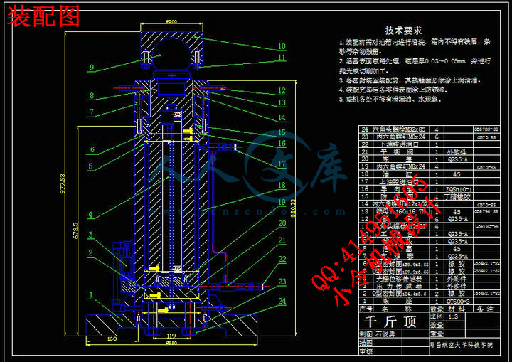
摘要:所设计的四顶顶升系统的主要参数是每只千斤顶高约1000mm,最大行程为400mm,最大载荷为20t。因千斤顶载荷较大,位置精度要求较高,故顶升速度不宜过大,最大顶升速度应控制在60mm/min以内。

工作原理是,二位四通电磁换向阀的电磁铁的工作状态是由单片机控制的,当换向阀电磁铁通电时,换向阀左位接入系统,油液经电磁换向阀和平衡阀进入油缸下腔,使得千斤顶上升,再从油缸上腔流出,经电磁换向阀和滤油器流回到油箱内,这时平衡阀的作用相当于一个单向阀;反之,当换向阀电磁铁断电时,换向阀右位接入系统,油液经换向阀流入油缸上腔,当上腔压力达到一定值时,平衡阀上位接入系统,这时平衡阀的作用相当于一个节流阀,油液从油缸下腔流出,经平衡阀、电磁换向阀和滤油器流回到油箱。从而实现了千斤顶升降换向功能,并具有过载保护和断电保护的功能。

为了适应复杂工作表面的工件,千斤顶的工作台与活塞杆应采用转动连接副相连当顶升系统工作时,液压千斤顶工作台可随工件表面形状进行自由转动调节,所以设计时将活塞杆顶部插入球头,与工作台形成转动副。

由于光栅尺的尺寸较长,将活塞和活塞杆做成中空状来放置光栅。工作时发光元件与光敏元件随活塞作同步运动,光栅尺下端固定在底盖上不动,光源与光栅尺的相对位移量通过读数头转化为数字信号传递给单片机。


关键词:      四顶同步顶升         单片机           光栅


Servo hydraulic jacks


Abstract: Digg this liter four-designed system, the main parameter is the high per jack about 1000mm, the maximum stroke is 400mm, the maximum load of 20t. Jack load due to a larger location with high precision, thus lifting speed should not be too large, the maximum lifting speed should be controlled within the 60mm/min.

    Works, the two four-way solenoid valve of the solenoid working state is controlled by the microcontroller, when the solenoid valve energized, the valve Left access system, oil by the solenoid valve and balancing valve into the cylinder under the cavity, so jack up, and from fuel tanks on the cavity flow, flow through solenoid valve and filter tank back in, then the role of balancing valve is equivalent to a one-way valve; the other hand, When the solenoid valve power, the valve access system the right position, oil flows through valve cylinder on the cavity, when the chamber pressure reaches a certain value, the upper balance valve access system, when a balance acts as a throttle valve, the oil flow from the fuel tank under the cavity, by balancing valve, solenoid valve and filter flow back to tank. In order to achieve a lifting jack for the function, and have overload protection and power protection.

    In order to adapt to the complex work piece surface, jack the table should be used with the piston rod connected to rotate connections made at work when lifting systems, hydraulic jack table with the surface shape can be adjusted freely rotate, so when the piston rod at the top of the design Insert the ball, and form a rotating table vice

    As the size of a long grating, the piston and piston rod to place the grating made of hollow shape. Work light emitting devices with photosensitive elements for synchronous movement with the piston, the bottom grating fixed to the bottom cover fixed, light source and grating by reading the relative displacement of the first into a digital signal is passed to the microcontroller.

Keywords:   4 Synchronous Lift       SCM         Grating

                      目录

1.  引言2

1.1 选题的依据及课题的意义2

1.2 国内外的研究概况3

1.3 单片机控制系统的发展概况4

1.4 PID控制算法的发展概况5

1.5 设计要求及工作内容6

1.6 目标、主要特色及工作进度7

2. 机械结构与液压传动系统设计7

2.1系统结构分析7

2.2 千斤顶零部件分析9

2.3 油缸与螺纹的校验12

2.3.1油缸的壁厚校验12

2.3.2 锁母螺纹牙剪切强度校验13

2.3.3锁母螺纹牙的弯曲强度校验14

2.4 液压系统分析14

2.5 液压泵与电动机的选择15

2.6 超高压泵站简介16

3 . 单片机控制系统设计17

3.1 单片机的选用及功能介绍17

3.2 片外存储器功能简介18

3.3 显示部分设计21

3.4 键盘部分设计25

3.5 交流异步电动机变频调速系统27

3.5.1 交流异步电动机变频调速原理28

3.5.2主电路和逆变电路工作原理28

3.5.3 变频与变压32

3.6 位移检测部分的设计38

3.6.1 位移检测传感器的选用38

3.6.2 光栅位移传感器与单片机的接口设计40

3.7 位移传感器部分的设计43

3.7.1 A/D转换器的选择43

3.7.2 压力传感器与单片机的接口设计47

4.系统的PID控制算法48

4.1 PID控制原理48

4.2  数字PID控制算法50

4.2.1 位置式PID控制算法50

4.2.2  增量式PID控制算法51

4.3  智能自适应PID控制器52

5. 系统模拟仿真57

5.1 SIMULINK概述58

5.2 SIMULINK的窗口和菜单58

5.3 用SIMUINK创建模型60

5.4 用SIMULINK进行系统仿真与分析61

5.4.1 建立控制系统模型61

5.4.2 系统模块参数设置与仿真参数设置62

5.4.3 系统仿真与分析64

6.结论67

7.致谢68

8. 参考文献68


1.  引言


1.1 选题的依据及课题的意义


随着现代社会的不断发展,工业化程度的不断深入,大尺寸、大重量、不规则表面的工件越来越多的成为工厂加工的对象。而在加工过程中如何将这些工件准确的提升至预定位置则成为最难解决的问题,这时传统的千斤顶和起重机等设备就显示出先天不足的缺陷来。也正是在这种环境下,同步顶升系统应运而生,并在建筑、机械加工、造船等行业扮演着越来越重要的角色。同步顶升系统是由控制系统协调控制多个千斤顶,使其具备顶升大重量、大体积、复杂工作表面的工件的能力,并具有同步升降、点动升降、连续升降、侧翻仰俯等功能的机电一体化设备。其控制系统可以是微机、单片机、可编程控制器等;其动力系统有液压式、气电式、汽液两用式等;吨位从几百公斤到几千吨不等,主要由动力方式和千斤顶的个数来决定 。由于其体积小、承载重、精度高、结构简单、控制方便、使用灵活等优点被广泛的用于电力、建筑、机械制造、矿山、铁路桥梁、造船等多种行业中,在设备安装、起顶拆卸、静力压桩、设备校调、基础沉降等工作岗位发挥了重要的作用。基于单片机控制、液压传动的四顶顶升系统是较常见的,控制算法较简单的一种。由于其控制简便、吨位适中、价格也很低廉的优点使得其在中小企业、民营单位甚至轻工业领域都有很高的使用度。其重要性不言而喻,对其进行研究和开发具有很大的市场空间和实用价值。


1.2 国内外的研究概况

国外对同步系统的研究起步较早,基于单片机控制、液压传动的四顶顶升系统是较常见的,控制算法较简单的一种。由于其控制简便、吨位适中、价格也很低廉的优点使得其在中小企业、民营单位甚至轻工业领域都有很高的使用度。美国实用动力ENERPAC是这一行业的佼佼者,在澳大利亚的昆士兰州,G&S 工程技术 服务公司就采用了 ENERPAC(恩派克)提供的同步顶升液压系统 成功地完成了重达 3500 多吨的矿山巨型索斗铲的顶升,误差小于 0.5mm。在上海因广场改造而需要整体平移的上海音乐厅使用了ENERPAC公司开发的一套具有四组共60个高精度顶升点的计算机控制同步顶升和顶推系统,以小于0.2mm的误差将建筑物同步顶升至预定高度并顺利完成平移任务。

   我国在这领域起步虽晚,但发展迅速,经过多年的发展也获得了许多曙目的成就,今年(2006年)1月4日,目前世界上最大的闸门——葛洲坝1号船闸重达200吨、面积相当于篮球场大的上游人字闸门安装就位。此举标志着我国自主研制的第一套大型船闸门同步顶升系统获得成功。在上海兴建的磁悬浮列车的关键基础部件轨道梁是确保磁悬浮列车快速、平稳、安全的重要保证,其加工精度要求非常高,但每段轨道梁长25米,重16吨,对其进行精确升举困难重重,上海千斤顶厂自主开发的高精度同步顶升装置不负众望,顺利完成任务,其同步顶升精度≤0.03mm,达到国际先进水平。我国浙江省海盐县有“千斤顶之乡”的美誉。在千斤顶和同步系统方面形成规模化生产,年生产能力达800万台以上,销量位居世界前列。


1.3 单片机控制系统的发展概况

单片机,就是单片微型计算机的简称,又称微控制器。自上世纪70年代面世以来不过短短30余年的历史,但因嵌入式应用而得到迅猛的发展,各种新颖的单片机层出不穷,令人目不暇接。它具有因体积小、成本低、控制能力强等优点,又由于现在开发环境的不断改善,正在以空前的速度迅速取代经典电子系统,广泛的应用于家用电器、机器人、工业控制单元、仪器仪表、汽车电子系统、金融电子系统、通讯系统等嵌入式产品中。

目前单片机的种类繁多,世界各国厂商已研制出大约50个系列、30多个品种的单片机产品。与早期经典的8位单片机MCS-51相比,无论是频率、字宽、寻址范围、集成度等方面都有了巨大的突破。现代科技的发展使得单片机的功能正日渐完善:

1、单片机集成越来越多资源,内部存储资源日益丰富,用户不需要扩充资源就可以完成项目开发,不仅是开发简单,产品小巧美观,同时系统也更加稳定,目前该方向即是发展为SOC(片上系统)。

2、单片机抗干扰能力加强,使的它更加适合工业控制领域,具有更加广阔的市场前景。

3、单片机提供在线编程能力,加速了产品的开发进程,为企业产品上市赢得宝贵时间。

4、在线仿真变的容易。用户一旦开发一个比较大的系统,开发调试变的非常复杂,同时由于单片机资源有限,不能象PC一样直接调试自己的软件,于是出现了品种繁多的专业仿真器,为用户的开发提供了强大功能,加速了开发进程,降低了开发难度。目前还已经有公司推出了可以在线调试的单片机,使得单片机系统的调试与开发变得更加方便、快速。

随着单片机的发展,人们对事物的要求越来越高,单片机的应用软件技术也发生了巨大的变化,从最初的汇编语言,开始演变到C语言开发,不但增加了语言的可读性,结构性,而且对于跨平台的移植也提供了方便,另外一些复杂的系统开始在单片机上采用操作系统,一些小的嵌入式实时操作系统(RTOS)等,一方面加速了开发人员的开发速度,节约开发成本,另外也为更复杂的实现提供了可能。当前比较流行的RTOS有:WINCE,uClinux,Linux,uC/OS等等。

本次设计的四顶同步顶升系统再选择控制系统时在综合考虑了微机、单片机和可编程控制器的成本、控制的难易程度和结构化布线等因素后,也拟定采用单片机进行控制。


内容简介:
IEEE TRANSACTIONS ON ROBOTICS, VOL. 24, NO. 5, OCTOBER 20081199Real-Time Adaptive Motion Planning (RAMP)of Mobile Manipulators in Dynamic EnvironmentsWith Unforeseen ChangesJohn Vannoy and Jing Xiao, Senior Member, IEEEAbstractThis paper introduces a novel and general real-timeadaptive motion planning (RAMP) approach suitable for plan-ning trajectories of high-DOF or redundant robots, such as mobilemanipulators, in dynamic environments with moving obstacles ofunknown trajectories. The RAMP approach enables simultaneouspath and trajectory planning and simultaneous planning and exe-cution of motion in real time. It facilitates real-time optimizationof trajectories under various optimization criteria, such as min-imizing energy and time and maximizing manipulability. It alsoaccommodates partially specified task goals of robots easily. Theapproach exploits redundancy in redundant robots (such as lo-comotion versus manipulation in a mobile manipulator) throughloose coupling of robot configuration variables to best achieve ob-stacleavoidanceandoptimizationobjectives.TheRAMPapproachhasbeenimplementedandtestedinsimulationoveradiversesetoftask environments, including environments with multiple mobilemanipulators. The results (and also the accompanying video) showthat the RAMP planner, with its high efficiency and flexibility, notonly handles a single mobile manipulator well in dynamic environ-ments with various obstacles of unknown motions in addition tostatic obstacles, but can also readily and effectively plan motionsfor each mobile manipulator in an environment shared by multiplemobile manipulators and other moving obstacles.Index TermsAdaptive, dynamic obstacles of unknown motion,loose coupling, mobile manipulators, partially specified goal, realtime, redundant robots, trajectory optimization.I. INTRODUCTIONMOTION PLANNING is a fundamental problem inrobotics1,2concernedwithdevisingadesirablemo-tion for a robot to reach a goal. Motion planning for high-DOFarticulated manipulators or mobile manipulators is more chal-lenging than for mobile robots because the high-dimensionalconfiguration space of a robot has little or no resemblance tothe physical space that the robot works in, and how to constructManuscriptreceivedMay16,2007;revisedDecember13,2007andMarch5,2008. First published October 10, 2008; current version published October 31,2008. This paper was recommended for publication by Associate EditorK. Yamane and Editor L. Parker upon evaluation of the reviewers comments.A preliminary part of this paper was presented at the IEEE International Con-ference on Intelligent Robots and Systems, Sendai, Japan, 2004.The authors are with the Intelligent, Multimedia and Interactive Systems(IMI) Laboratory, Department of Computer Science, University of NorthCarolina at Charlotte, Charlotte, NC 28223 USA (e-mail: jmvannoy; xiao).Thispaperhassupplementarydownloadablematerialavailableat, provided by the authors: a video showing the real-time planning and execution of mobile manipulator motion by our RAMPalgorithm. This video is 14 MB in size.Color versions of one or more of the figures in this paper are available onlineat .Digital Object Identifier 10.1109/TRO.2008.2003277a configuration space higher than three dimensions efficientlyremains a largely unsolved problem.A. Related Research on Motion PlanningRandomized algorithms, such as the popular probabilisticroadmap (PRM) method 3 and rapidly exploring random tree(RRT) method 4, are found to be very effective in findinga collision-free path for a robot with high DOFs offline be-cause such algorithms avoid building the robots configurationspace explicitly by sampling the configuration space. The PRMmethod has inspired considerable work on improving samplingand roadmap construction 2, including a recent paper 5 onproducing compact roadmaps to better capture the different ho-motopic path groups. By building a tree rather than a graph, theRRTmethodismoresuitableforgeneratingapathinoneshotorgeneratingatrajectorydirectlyandthusmoresuitableforonlineoperation 6. Both methods have seen many variants 2.There are also methods for path planning based on ge-netic algorithms (GAs), or more broadly, evolutionary com-putation 7, 8, which are general frameworks of randomizedsearch subject to user-defined optimization criteria. Such op-timization techniques have been used widely and successfullyin many application domains 8, 9 to tackle NP-hard opti-mization problems. There are two major ways of applications.One straightforward way is to map a problem into the formsuitable for a standard, off-the-shelf GA, solve it by runningthe GA, and then, map the results back to the application do-main. This one-size-fit-all approach is often not effective be-cause it forces artificial transformation of a problem into some-thing else that is confined in the format of a standard GA butmaylosecertainimportantnatureoftheoriginalproblem.SomeGA-based path planning methods 10, 11 adopt such an ap-proach, where C-space is discretized into a grid, and a path is interms of a fixed-length sequence of grid points. As the standardGA operates on fixed-length bit strings, search is often veryslow.A more effective approach is to adopt the general idea ofevolutionary computation to solve a problem in a more naturalandsuitablerepresentation.Thepathplanningmethodsreportedin 1214 belong to such a customized approach. A real-timepathplanningmethodisreportedin12for2DOFpointmobilerobots, which is extended in 13 for 3 DOF point flying robotswith specific constraints. A multiresolution path representationis proposed in 14 for path planning. However, all evolution-ary algorithms have a number of parameters that must be setappropriately, which is often not a trivial task.1552-3098/$25.00 2008 IEEE1200IEEE TRANSACTIONS ON ROBOTICS, VOL. 24, NO. 5, OCTOBER 2008Unlike path planning, motion planning has to produce anexecutable trajectory for a robot in configurationtime space,or CT-space, and not merely a geometrical path. A commonapproach is to conduct trajectory planning on the basis of a pathgenerated by a path planner. A notable framework is the elasticstrip method 15, which can deform a trajectory for a robotlocallytoavoidmovingobstaclesinsideacollision-free“tunnel”that connects the initial and goal locations of the robot in a 3-Dworkspace. Such a “tunnel” is generated from a decomposition-based path planning strategy 16. The other approach is toconduct path and trajectory planning simultaneously. However,most effort in this category is focused on offline algorithmsassumingthattheenvironmentiscompletelyknownbeforehand,i.e., static objects are known, and moving objects are knownwithknowntrajectories1720.Asfordealingwithunknownmoving obstacles, only recently some methods were introducedfor mobile robots 21, 22.The combination of mobility and manipulation capabilitymakes a mobile manipulator applicable to a much wider rangeof tasks than a fixed-base manipulator or a mobile robot. For amobile manipulator, a task goal state is often partially specifiedas either a configuration of the end-effector, which we call aplace-to-place task, or a desired path (or trajectory) of the end-effector, which we call a contour-following task, and the targetlocation/path of the base is often unspecified.Here, a major issue of motion planning is the coordination ofthe mobile base and the manipulator. This issue, as it involvesredundancy resolution, presents both challenges and opportu-nities. There exists a rich literature addressing this issue frommany aspects. Some researchers treat the manipulator and themobile base together as a redundant robot in planning its pathfor place-to-place tasks 2325. Some focused on planning asequence of “commutation configurations” for the mobile basewhen the robot was to perform a sequence of tasks 26, 27subject to various constraints and optimization criteria. Othersfocused on coordinating the control of the mobile base and themanipulator in a contour-following task 28, 29 by tryingto position the mobile base to maximize manipulability. Manyconsidered nonholonomic constraints.While most of the existing work assumes known environ-ments with known obstacles for a mobile manipulator, a fewresearchers considered local collision avoidance of unknown,moving obstacles online. One method 30 used RRT as a localplanner to update a roadmap originally generated by PRM todeal with moving obstacles. For contour-following tasks, an ef-ficient method 31 allows the base to adjust its path to avoid amoving obstacle if possible while keeping the end-effector fol-lowing a contour, such as a straight line. Another method 29allowed the base to pause in order to let an unexpected obsta-cle pass while the arm continued its contour-following motionunder an event-based control scheme. Other methods includeone based on potential field 32 to avoid unknown obstaclesand one based on a neuro-fuzzy controller 33 to modify thebase motion locally to avoid a moving obstacle stably. Thereis also an online planner for the special purpose of planningthe motions of two robot arms getting parts from a conveyerbelt 34.However, we are not aware of any existing work that can planmotions of high-DOF robots globally among many unknowndynamic obstacles.B. Our Problem and ApproachPlanning high-DOF robot motion in such an environmentof many unknown dynamic obstacles poses special challenges.First, planning has to be done in real time, cannot be done of-fline, and cannot be based on a certain prebuilt map because theenvironment is constantly changing in unforeseen ways, i.e.,the configuration space obstacles are unknown and changing.Examples of such environments include a large public squarefull of people moving in different ways, a warehouse full ofbusy-moving robots and human workers, and so on. Such anenvironment is very different from static or largely static envi-ronments or known dynamic environments (i.e., with other ob-ject trajectories known), where motion planning can reasonablyrely on exploring C-space (for known static environments) orCT-space(forknowndynamicenvironments)offline(suchasbyPRM). The elastic strip method provides the flexibility to makesmall adjustments of a robot motion to avoid unknown motionsof obstacles, if the underlying topology of the C-space does notchange. For an environment with changing C-space topologyin unknown ways, a planned path/trajectory can be invalidatedcompletelyatanytime,andthus,real-timeadaptiveglobalplan-ning capability is required for making drastic changes of robotmotion. Planning and execution of motion should be simulta-neous and based on sensing so that planning has to be very fastand always able to adapt to changes of the environment.By nature, to tackle motion planning in an unknown dynamicenvironment cannot result in a complete planning algorithm.That is, no algorithm can guarantee success in such an unknownenvironment. We can only strive for a rational algorithm thatserves as the “best driver of a high-DOF robot, but even thebest driver cannot guarantee to be accident-free if other thingsin the environment are not under his/her control.This paper addresses the problem of real-time simultaneouspath and trajectory planning of high-DOF robots, such asmobile manipulators, performing general place-to-place tasksin a dynamic environment with obstacle motions unknown.The obstacle motions can obstruct either the base or the armor both of a mobile manipulator. We introduce a unique andgeneral real-time adaptive motion planning (RAMP) approach.Our RAMP approach is built upon both the idea of randomizedplanning and that of the anytime, parallel, and optimizedplanning of evolutionary computation, while avoiding thedrawbacks. The result is a unique and original approacheffective for the concerned problem.The RAMP approach has the following characteristics.1) Whole trajectories are represented at once in CT-spaceand constantly improved during simultaneous plan-ning and execution, unlike algorithms that build apath/trajectory sequentially (or incrementally) so that awholepath/trajectorycanbecomeavailableonlyattheendof the planning process. Our anytime planner can providea valid trajectory quickly and continue to produce betterVANNOY AND XIAO: REAL-TIME ADAPTIVE MOTION PLANNING (RAMP) OF MOBILE MANIPULATORS IN DYNAMIC ENVIRONMENTS1201trajectories at any later time to suit the need of real-timeglobal planning.2) Different optimization criteria (such as minimizing en-ergy and time and optimizing manipulability) can beaccommodated flexibly and easily in a seamless fash-ion. Optimization is done directly in the original, con-tinuous CT-space rather than being confined to a certainlimited graph or roadmap. Trajectories are planned andoptimized directly rather than conditional to the results ofpath planning.3) Our planner is intrinsically parallel with multiple diversetrajectories present all the time to allow instant, and ifnecessary, drastic adjustment of robot motion to adapt tonewly sensed changes in the environment. This is differ-ent from planners capable of only local trajectory adjust-ment based on a known set of homotopic paths. It is alsodifferent from sequential planners, such as anytime A*search 35, which also requires building a discrete statespace for searcha limitation that our planner does nothave.4) Trajectory search and evaluation (of its optimality) areconstantly adaptive to changes but built upon the resultsof previous search (i.e., knowledge accumulated) to beefficient for real-time processing.5) As planning and execution (i.e., robot motion followingthe planned result so far) are simultaneous, partially feasi-ble trajectories are allowed, and the robot may follow thefeasible part of such a trajectory (if it is the current best)and switch to a better trajectory to avoid the infeasiblepart.6) With multiple trajectories from our planner, each trajec-tory can end at a different goal location in a goal region,i.e.,partiallyspecified goals,ratherthan asinglegoalcon-figuration.7) Our planner represents a trajectory for a redundant robot,such as a mobile manipulator, as loosely coupled trajec-tories of redundant variables to take advantage of the re-dundancy in order to best achieve obstacle avoidance andvarious optimization objectives.The rest of the paper is organized as follows. Section II pro-vides an overview of our RAMP approach; Sections III and IVdescribe problem representation and initialization; Section Voutlines our optimization criteria for trajectory evaluation anddescribes the strategies for evaluation. Sections VI and VII de-scribe the strategies to alter trajectories to produce better ones.Section VIII describes how the RAMP planner can create andpreserve a diverse set of trajectories. Section IX provides im-plementation and experimentation results and discusses perfor-mance of the planner. Section X concludes the paper.II. OVERVIEW OF THERAMP APPROACHOnebasicpremiseofourapproachisthattheplanningprocessand the execution of motion are interweaving to enable simul-taneous robot motion planning and execution. This is achievedthrough our anytime planning algorithm that always maintainsa set of complete trajectories in the CT-space of the robot calleda population. The feasibility and optimality of each trajectory,called fitness, is evaluated through an evaluation function cod-ing the optimization criteria. Feasibility refers to collision-freeandsingularity-free.Bothinfeasibleandfeasibletrajectoriesareallowed in a population. Feasible trajectories are considered fit-ter than infeasible trajectories. Within each type, trajectories arecompared for optimality in fitness.Theinitialpopulationisacombinationofrandomlygeneratedand deliberately seeded trajectories. Deliberately seeded trajec-tories include ones constructed to represent distinct subpopula-tionsinordertoachievecertaindiversityinthepopulation.Iftheenvironment contains known static obstacles, trajectories basedon preplanned feasible paths with respect to the known staticobstacles can also be included. See Section IV for more details.Once the initial population is formed, it is then improved to afitterpopulationthroughiterationsofimprovements,calledgen-erations. In each generation, a trajectory is randomly selectedandalteredbyarandomlyselectedmodificationoperatoramonga number of different modification operators, and the resultingtrajectory may be used to replace a trajectory that is not thefittest to form a new generation. The fittest trajectory is alwayskept in the population and can only improve from generation togeneration. Each generation is also called a planning cycle.To improve the fitness of the initial population, a number ofinitial planning cycles may be run based on the initial sensinginformation of the environment before the robot begins execut-ing the fittest trajectory. The robot need not wait for a feasibletrajectory to emerge; if no feasible trajectory is available, therobot will begin moving along the fittest in feasible trajectorywhilecontinuing the search forafitter,and hopefully willlocatea feasible trajectory before it comes within a distance thresholdD of the first predicted collision or singularity of the executedtrajectory. This strategy makes sense because: 1) the presentlypredicted infeasible trajectory may become feasible later andvice versa; 2) as to be described later, our planner makes therobot switch to a better trajectory if one is available, and thus,before the infeasible part of the currently followed trajectory isencountered, the robot may already switch to a better trajectory;3) the strategy allows limited sensing, in which the robot maynot sense an obstacle until getting closer; and 4) it provides ameasure of safety in trajectory evaluation (see Section V).As the robot moves, planning continues to improve the popu-lation of trajectories until the next control cycle, when the robotcan switch to a fitter trajectory so that it always follows the besttrajectory. For that purpose, each trajectory is always updatedto start from the current robot configuration with the currentvelocity when a new control cycle begins. For the trajectory thatis being followed, this means that the executed portion of thetrajectory is dropped from the trajectory, while for every othertrajectory, it means that only the starting configuration and ve-locity are changedthe rest of the knot points on the trajectory(see Section III) remain intact. Note that each control cycle heredoes not necessarily have to be a servo cycle of the low-levelcontroller. Our control cycle, which is high level for controllingthe rate of adaptation, can be longer than a servo cycle to ensurethat within a control cycle, there can be more than one planningcycle. This is because adaptation is guided by planning.1202IEEE TRANSACTIONS ON ROBOTICS, VOL. 24, NO. 5, OCTOBER 2008Fig. 1.Relationship among planning, control, and sensing cycles.Changes in a dynamic environment are sensed and fed to theplanner in each sensing cycle, which lead to updated fitnessvalues of trajectories in the subsequent planning cycles, andunknown motions of moving obstacles are predicted in fitnessevaluation of robot trajectories. The presence of a diverse popu-lationofever-improvingtrajectoriesenablestherobottoquicklyadapt to changes in the environment. It does so by following thefittest trajectory under each circumstance: when the current tra-jectory that the robot follows becomes worse or can no longerbe followed due to imminent collision (i.e., the threshold D isreached), the robot may not need to stop its motion and replanfromscratch;rathertheplanneroftenmerelyneedstoswitchtherobot to a feasible or better trajectory in the population swiftlyin a seamless fashion. The chosen trajectory can be of a verydifferent homotopic group from the previous one to deal withdrastic and large changes.In the case when the robot reaches D of the current trajectorybut finds no better trajectory to switch to, it will stop its motionatD,whichiscalleda forcedstop.However,theRAMPplanner(i.e.,therobots“thinking”process)neverstops,anditcontinuesto plan and search for a better trajectory for the robot. The robotresumes its motion once a better trajectory is found.Suchplanning/control/sensingcyclescontinuetointeractandmove the robot toward a goal configuration in the best possibleway in real time: improving the trajectories it follows if there isno change in the environment, or both adapting and improvingthe trajectories if there is a sensed change. Fig. 1 illustratesa possible relationship among planning, control, and sensingcycles (note that the planning cycles actually vary in length).The RAMP algorithm is outlined as Algorithm 1.Unlike an evolutionary algorithm, we use random selectionand random modification operators that cannot be called “muta-tion” operators because they introduce drastic rather than smallchanges to create a diverse population of trajectories ready toadapt to changing environments. Our RAMP algorithm furthermaintainsdiversityandpreventshomogeneityinapopulationoftrajectories by creating and preserving distinct subpopulationsof trajectories as explained in detail in Section VIII. Moreover,the RAMP algorithm does not need tuning probabilities as wellas most other parameters that many evolutionary algorithms do.As the result, it is easy to implement and is robust to differenttask environments. In fact, our algorithm only needs to decidethe parameter population size, but the value can be invariantor rather insensitive to many different environments, as will bedescribed later in Section VIII.The fitness evaluation procedure of RAMP is also original,incorporating multiple criteria that are often not considered inmany other motion planning algorithms, and not only feasiblebut also infeasible trajectories are evaluated.Our RAMP approach also supports the partial specificationof a goal: only the end-effector position and orientation withrespect to the world coordinate system are needed. Differenttrajectories may hold different goal base configurations and armconfigurations (that achieve the same end-effector goal) in thecase of mobile manipulators so that redundancy is exploited toachieve flexibility amid environments with dynamic changes.The details of the RAMP algorithm are presented in the sec-tions next.III. TRAJECTORYREPRESENTATIONWerepresentatrajectoryofamobilemanipulatoruniquelyasa pair of loosely coupled manipulator and base subtrajectorieswith the following characteristics.1) For the manipulator subsystem, a path of knot configu-rations is specified in the joint space, based on which acubic-splined trajectory is used.2) For the base subsystem, a path of knot configurations isspecified in the Cartesian space of the world coordinateVANNOY AND XIAO: REAL-TIME ADAPTIVE MOTION PLANNING (RAMP) OF MOBILE MANIPULATORS IN DYNAMIC ENVIRONMENTS1203Fig. 2.Loose coupling of locomotion and manipulation.system,basedonwhichalinear-with-parabolic-blendstra-jectory is used.3) Either trajectory as a function of time may consist ofvariable segments of constant values, i.e., intervals ofno movement, and these time intervals may or may notoverlap between the two trajectories. This is the key toachieve loosely coupled behavior: either subsystem canmove while the other does not,1or they can move at thesame time.4) Two subsystem trajectories are aligned in time to forma trajectory that uniquely determines the motion of thewhole system.Fig. 2 illustrates this notion with one joint trajectory and onedimension of the base trajectory.Themainadvantageofloosecouplingforplace-to-placetasksisitsflexibilityindealingwithuncertaindynamicenvironments:when a dynamic obstacle shows up, sometimes an agile armmovement makes a better avoidance motion than a heavy basemovement; sometimes it is more efficient to vary the motion ofthe base rather than having a large motion of the arm (especiallyif a large payload is held by the end-effector); sometimes bothneed to move to make an avoidance; and sometimes it is moreenergy and even time efficient to just stop the entire systemfor some period to let the obstacle pass. Our RAMP plannerof loosely coupled motion allows all the previous varieties tohappen based on the circumstance.A trajectory leads the mobile manipulator from its currentconfiguration (with certain velocity and acceleration) to one ofthe goal configurations. Each subtrajectory may consist of anarbitrarynumber ofsegments,separatedbyknotconfigurations,alsocalledknotpoints.Thedatastructureforeachsegmentcon-tains the bounding knot points of the segment, the informationof feasibility and fitness of the segment (see Section V), and thedesired velocities and accelerations at the bounding knot pointsif the segment is feasible.Each nonconstant trajectory segment is generated using theminimum time for the slowest joint (including the base) of therobot to move from the starting knot point to the ending knotpoint of the segment, taking into account constraints on speedand acceleration. For the arm, the segment for each joint isa cubic polynomial of time, and for the base, the segment is alinearfunctionwithparabolicblends.Specifically,theminimumexecution time Tijof each joint i for each path segment j is firstcalculated based on the cubic trajectory, under the maximumacceleration and maximum speed constraints of joint i. For the1Note that when we say “the base moves while the arm does not move,” wemean that the arm has no relative motion to the base.Fig. 3.Illustration of arm and base trajectory populations with gripper goal at“G.”same path segment j, the minimum time for the base i = 0is also calculated based on a linear trajectory with parabolicblendsunderitsmaximumaccelerationandvelocityconstraints.Next,themaximumofTijamongalljoints(includingthebase),Tmax,j, is used as the time needed to complete the path segmentj. Based on Tmax,j, the corresponding trajectory segment (forthe arm and for the base) can be generated.Note that more sophisticated methods taking into accountdynamics and torque constraints 36, 37 can be used to de-termine minimum-time trajectories. However, here we need tocompromise computation for true minimum-time trajectory forreal-time performance in planning.Fig. 3 illustrates a robot and its arm and base trajectory pop-ulations, respectively. Each trajectory is indicated by line seg-ments connecting wrist position or base position at each knotpoint. Note that the lines themselves are simply to show the or-derinwhichtheknotpointsarevisitedineachpathandcertainlynot the actual paths. The heavy line in each figure indicates thepath with the highest fitness for its trajectory.IV. INITIALIZATIONAn initial population is a combination of randomly generatedand deliberately seeded trajectories. The RAMP algorithm gen-erates random trajectories made up of randomly chosen knotconfigurations as uniform samples within the joint limits of themanipulator and the workspace boundaries of the base. Theinitial base and arm configuration, respectively, determine thestartingpointofeach.Anendingbaseconfigurationisrandomlygenerated within a reasonable neighborhood of the goal gripperlocation so that the gripper goal can be reached. Inverse kine-matics is used to find a corresponding ending arm configurationin joint space. A random number of intermediate knot pointsare inserted into the bases trajectory and the arms trajectory.Each knot point is a randomly sampled configuration. Once theknot points are created, the trajectory can be computed (seeprevious section). The other information about each trajectorysegment in the segment data structure is determined throughfitness evaluation of the trajectory.The RAMP algorithm can also deliberately seed the initialpopulation with trajectories built based on different “departingdirections” to provide diversity (more on this in Section VIII).1204IEEE TRANSACTIONS ON ROBOTICS, VOL. 24, NO. 5, OCTOBER 2008Moreover, the initial population can also include trajectoriesbased on preplanned paths feasible with respect to known staticobstacles. Such preplanned paths can be obtained from anexisting method (e.g., PRM or RRT) or from running our offlineplanner (see Algorithm 3). In this way, RAMP can take ad-vantage of the existing offline planners capabilities in dealingwith challenging static environments (such as handling “narrowstatic passages” as some PRM variants are focused on).V. FITNESSEVALUATIONThe use of explicit fitness evaluation functions enables flexi-ble applications of different optimization criteria and combina-tion and aggregation of multiple criteria. In our planner, fitnessevaluation has two components: feasibility checking and opti-mization criteria. We use two different evaluation functions forfeasible and infeasible trajectories. In each case, the evaluationfunction is a cost function to measure the fitness of a trajectory.The higher the value of the evaluation function, the worse orless fit a trajectory is.A. Feasibility CheckingWe currently use two hard constraints to define feasibility ofa trajectory: collision-free and singularity-free.Once a trajectory is generated (Section III), our plannerchecks a discretized trajectory for feasibility. Thus, it needsto make sure that there is no missed collision or singular con-figurations between two adjacent, discrete configurations. Ourstrategy to avoid missing collisions is to enlarge the obstaclesslightly before collision checks. In the same spirit, we considera configuration whose manipulability cost 38 is higher thana threshold, i.e., very close to a singular configuration, to be asingular configuration.A trajectory is feasible if it is collision-free and singularity-free during the entire time period. A trajectory segment is feasi-bleifeveryinterpolatedconfigurationisfeasibleatitstimestep;likewise, if all trajectory segments are feasible, a trajectory isfeasible. Otherwise, it is called infeasible.B. Evaluation Function for Feasible TrajectoriesThe evaluation function for a feasible trajectory combinesthree optimization criteria, which are in fact soft constraints:1) time (minimize);2) energy (minimize);3) manipulability (maximize).The execution time of a trajectory is simply the sum?jTmax,jof the time durations of all its segments.Sincethemotionsofthemobilebaseandthemanipulatorarmare not decoupled so that they can happen together, minimizingtime as a measure alone cannot differentiate an efficient trajec-tory with minimum motion from another one with unnecessaryarmorbasemovementwhiletheyhavethesameexecutiontime.Therefore, we use minimum energy as another measure of op-timality. This way, we can distinguish between two trajectorieswhose time requirements are equal but energy requirements arenot; the one that requires less energy is preferred.The energy calculation for a trajectory is a simple but ef-fective approximation: our interest is not in determining theprecise energy consumption in executing a trajectory, but ratherin comparing and ranking energy consumptions of different tra-jectories. Therefore, an estimate is sufficient for our need. Weapproximate the shapes of the base and the arm links of a mo-bile manipulator by cylinders to simplify the computation ofthe inertia tensors. After a feasible trajectory is generated, wecompute the energy consumption of each link (treating the baseas link 0) in terms of the total kinetic energy changes of the linkduring the entire trajectory and sum up energy consumption ofall links as the energy consumption of the trajectory.2Finally, to evaluate the manipulability associated with a tra-jectory, we take the manipulability measure at each configura-tion on each trajectory segment. The inverse of this value willgrow in proportion to the proximity to a singularity, and cantherefore give a measure of cost. We take the average of suchinverse values along the whole trajectory as the cost related tomanipulability.The overall fitness value for a feasible trajectory is a combi-nation of the energy cost E, the time cost T, and the cost Mrelated to manipulability of the trajectoryCost = C1Ea1+ C2Ta2+ C3Ma3whereCi,i = 1,2,3,isaweightthatindicatestheimportanceofthe respective cost, and aiis a normalization factor determinedas the estimated largest respective cost.C. Evaluation Function for Infeasible TrajectoriesIfatrajectoryisinfeasible,wedefineafitnessvalueasthesumof a dominating penalty term P and the trajectorys evaluationfunction value Cost as if it were feasible.3The large penaltyterm P serves two purposes. One purpose is to make sure thatinfeasible trajectories are less fit than feasible trajectories. Theother is to serve as a measure of relative safety so that infeasibletrajectories with smaller penalty terms are considered safer andthereforefitterthanones withlarger penalty terms.For thelatterpurpose, we define the penalty term of an infeasible trajectoryas P = Q/Tcoll, where Q is a large constant4and Tcollis the2Note that since vertical components in linear velocities are considered in thecomputation,changesinpotentialenergyarealreadyincluded.Asalltrajectoriesshare the same starting state, they share the same starting energy.3For a trajectory with singularities, we compute its “manipulability as if itwere feasible” by excluding the singular configurations.4Q is set to 104in our experiments.VANNOY AND XIAO: REAL-TIME ADAPTIVE MOTION PLANNING (RAMP) OF MOBILE MANIPULATORS IN DYNAMIC ENVIRONMENTS1205timebeforeeitherthefirstpredictedcollisionorthefirstsingularconfiguration, whichever comes first, in the trajectory. That is,we consider an infeasible trajectory safer if it has a longer timebefore the first predicted collision/singularity. The value Costis used as an indicator of the potential fitness of an infeasibletrajectory if it becomes feasible due to modification operations.By allowing infeasible trajectories in a population, our algo-rithm aggressively maximizes the chances to optimize a robotsreal-time actions efficiently. Often infeasible trajectories maylead to good feasible trajectories later.D. RemarksIt should be noted that in addition to the optimization criteriaconsidered, other criteria could be used and aggregated into theevaluation function for either feasible trajectories or infeasibletrajectories, requiring changes only in the evaluation procedure,and not to the overall algorithm. We could choose to optimizefeasible trajectories based on any number of criteria, includ-ing, for example, safety and stability measures 39. For non-holonomic mobile manipulators, the nonholonomic constraintscould be added as additional hard constraints for evaluatingthe feasibility of a trajectory and incorporated in the evaluationfunction for infeasible trajectories.Note also that regardless of whether a trajectory is feasible orinfeasible, the corresponding evaluation function is computedas the sum of the costs for individual trajectory segments. Thisproperty greatly facilitates efficient evaluation of trajectories ineach generation of the RAMP algorithm since only the alteredand affected trajectory segments need to be reevaluated, espe-cially in real time. The evaluation of infeasible trajectories isfurther speeded up by that once the first collision is detectedbetween a single link of a robot and an obstacle, the entire tra-jectory is labeled infeasible, and no further collision checking isrequired by the evaluation function (for infeasible trajectories).VI. MODIFICATIONOPERATIONSRecallthatineachgenerationofourRAMPalgorithm,certainmodification operations are performed on certain trajectories togenerate hopefully fitter trajectories. We use the following sixmodification operations.1) InsertAnew,randomknotpointisinsertedbetweentworandomly chosen adjacent knot points of a path.2) DeleteA randomly selected knot point is deleted.3) ChangeArandomlyselectedknotpointisreplacedwitha new, randomly generated knot point.4) SwapTwo randomly selected adjacent knot points froma single path are swapped.5) CrossoverThe knot point lists of two paths are dividedrandomly into two parts, respectively, and recombined:the first part of the first path with the second part of thesecond path, and the first part of the second path with thesecond part of the first path.6) StopThe base movement or arm movement stops at arandomly chosen knot point for a random duration.Thefirstfiveoperationsareusedtochangetheshapeofapath,and subsequently, the corresponding trajectory. The Stop oper-ation is used to change a trajectory only. We simply randomlyselect one of those operations (also called operators) to apply tothe selected trajectory(s). All operators are used to change thetrajectories of the base and the manipulator either separately ortogether in a stochastic fashion.The Stop operator enables loose coupling of subsets of vari-ables that have redundancy in a redundant robot, which, in thecase of a mobile manipulator, means loose coupling of trajecto-ries of the base and the manipulator. Both subsystems can stoptheir movements independently or together. The probabilisticnatureofourapproachsimplyoffersastopasapossibility;inthecaseswherestoppingisadvantageous, theplanner willutilizeit.Note that except for Crossover, the other operations aboveare unary transformations that change a single trajectory. Thecrossover generates two offsprings from two parent trajectories.The evaluation of a new trajectory can be very fast sinceeach operation only alters certain trajectory segments, and onlythe altered segments need to be reevaluated. As shown in theRAMP algorithm (Algorithm 1), the fitter offspring is put backinto the population to replace a trajectory that is not the solemember of a subpopulation to preserve diversity (more on thisin Section VIII). The fittest trajectory in the entire populationis always kept in the new population for the next generationP(t + 1). Note that P(t) and P(t + 1) are of the same size anddiffer in one trajectory.VII. REAL-TIMEADAPTIVENESSAs shown in Algorithm 1, at the end of each control cycle,all trajectories in the population are updated so that their initialconfiguration and velocity becomes the robots current config-uration and velocity. Since a feasible trajectory may emerge asthe result of continued planning, the manipulator may readilychange course to execute this new best trajectory instead whenthe new control cycle begins. Note that when the robot changescourse from one trajectory to another, the new trajectory is in-deedbetterevenaftertakingintoaccountthecostofchange(i.e.,the possible acceleration or deceleration needed for the change)as ensured by the fitness evaluation function (Section V). Thus,the change is smooth and stable, and the actual trajectory exe-cuted by the robot is the best or most rational result.When a change in the environment is sensed (from a sensingcycle), the constantly running planner will adapt the trajectorypopulation to the change in real time in that trajectories arerechecked for feasibility and fitness values against the changedor changing part of the environment. The processing effort toreevaluateiskepttoaminimum:theplanneronlychecksforcol-lisions against obstacles that have moved or are moving duringthat sensing cycle.When there are moving obstacles, our planner predicts thefuture trajectory of each moving obstacle. From an obstaclessensed configurations at the past two sensing cycles and thecurrent sensing cycle, i.e., at time ti2, ti1, and ti(the currenttime), we can compute (approximately) the linear and angularvelocities of the object v(ti1), v(ti), and (ti). The obstaclesmotionispredictedasoneofthefoursimpletypes:1)translationonly with nonzero v(ti) if (ti) is close to zero; 2) self-rotationonly with nonzero (ti) if v(ti) is close to zero; 3) translation1206IEEE TRANSACTIONS ON ROBOTICS, VOL. 24, NO. 5, OCTOBER 2008Fig. 4.Dynamic trap caused by high-frequency cyclic motion of obstacle.(a) Robot plans motion to avoid the moving obstacle. (b) Obstacle reversesdirection; robot does likewise. (c) Obstacle reverses direction again; the processrepeats.and self-rotation with nonzero v(ti) and (ti) if v(ti1) andv(ti) have similar directions; and 4) a global rotation (aboutan axis not through the object) with nonzero v(ti) and (ti) ifv(ti1) and v(ti) have different directions. The axis for globalrotation is along (ti) and away from the reference position ofthe obstacle by a distance r(ti), which can be computed fromv(ti) and (ti). The planner next checks the robots trajectoryagainst this predicted trajectory of each obstacle to see if therewill be a collision. Our prediction only has to be good enoughfor a short period before the next sensing cycle (which may belonger or shorter than a control cycle) since it will be correctedconstantly with newly added sensory information. Thus, thesimple method suffices.Note that to predict any cyclic or periodic behavior of an ob-ject, such as moving back and forth in opposite directions, morepreviousstatesneedtobeobservedbyourmotionpredictor,withmore computation cost. Fortunately, if the cyclic behavior has avery high frequency, we can detect that from just a few previousstateswithoutaddingmuchcomputationcost,andsubsequently,the planner will take into account the cyclic behavior of an ob-stacle in planning feasible trajectories for a robot to avoid thedynamic trap. If the frequency of the objects cyclic motion ishigher than or comparable to the sensing frequency, then as fewas the past four sensing cycles can review the cyclic tendency.Conversely, if the cyclic behavior of an obstacle has a ratherlow frequency, we can afford not to detect it because it does notreally trap a robot. Figs. 4 and 5 illustrate these concepts.VIII. DIVERSITYCREATION ANDPRESERVATIONThe need for a diverse population of trajectories can be ev-ident from the following example. Fig. 6 shows a task thatrequires a robot to pass through one of several doorways to theFig. 5.Low-frequency cyclic obstacle motion does not present a trap. (a)Robot plans motion to avoid the moving obstacle. (b) Obstacle has not yetreverseddirection.(c)Obstaclereversesdirection,butrobothasalreadyreachedgoal.Fig. 6.Task that requires a population of trajectories as doors can close andopen unexpectedly. The initial trajectory set has a good diversity to cover theenvironment. The figure indicates base trajectories only.other side of the room. However, each door may open or closeunexpectedly at any time; therefore, the robot should be alwaysprepared to move out of a trajectory leading to a closed doorand switch to a trajectory leading to an open door. As trajecto-ries through different doorways belong to different homotopicgroupsandarethusquitediverse,itisnecessarythatthepopula-tion of trajectories that RAMP creates and maintains be diversewith a good coverage of different homotopic groups. As shownin Fig. 6, a randomly generated initial population of base tra-jectories can be quite diverse. The key then is for the RAMPalgorithm to preserve or further promote such diversity.Clearly, since the robot operates in a changing environmentwith unknown dynamics, its CT-space cannot be known before-hand. Let alone that even for a static, known environment, howto construct the C-space of a high-DOF robot efficiently re-mains an open problem. Therefore, it is impossible to create allVANNOY AND XIAO: REAL-TIME ADAPTIVE MOTION PLANNING (RAMP) OF MOBILE MANIPULATORS IN DYNAMIC ENVIRONMENTS1207Fig. 7.Assignment of subpopulations based on departure directions at eachcontrol cycle: each subpopulation is indicated by a shade of gray.homotopicgroupsoftrajectoriespreciselyatanymoment.Moreviable measures are needed.TheRAMPalgorithmpreservesadiversepopulationoftrajec-tories through the following measures: 1) not allowing identicaltrajectories in a population; 2) randomly selecting a trajectoryfor modification, rather than base the selection on fitness; 3)using modification operators that introduce drastic changes intrajectories; 4) replacing a randomly chosen trajectory ratherthan the least fit; and 5) creating and preserving subpopulationsof trajectories. The last measure is very important and is furtherexplained next.A. Subpopulations and Diversity PreservationOurRAMPalgorithmdividesapopulationoftrajectoriesintosubpopulations when a new control cycle begins based on theirdeparture directions at that time. The departure direction ofa trajectory is defined as the n-dimensional difference vectorfrom the initial configuration to the first knot configuration (fora robot with n DOF). We calculate the angle between thedeparture directions a and b of two trajectories with the dotproduct:a b = ab cos .If is larger than a threshold, then the two trajectories canbe viewed as belonging to two different subpopulations. Fromthe example of Fig. 7, we can see a strong correlation betweeneach base trajectorys homotopic group and the subpopulationit belongs to according to departure directions.Grouping n trajectories based on similar departing directionscan be expensive as it requires a time complexity of O(n2).Hence, we make the following compromise with time com-plexity O(n): pick a reference departure direction a, dividethe range of into a number of intervals, and compare eachdeparting direction to a to divide the population of trajecto-ries into subpopulations corresponding to the intervals. Thesesubpopulations still capture a rough level of diversity.Note that since the subpopulations are updated or reassignedateachnewcontrolcyclefromtheupdateddeparturedirections,Fig. 8.Without diversity preservation, the fittest homotopic group dominates.The figure indicates base trajectories only.diversity over time is captured and preserved. If two trajectoriesareintwosubpopulations attimetbased onthedeparture direc-tions of the then control cycle but become very similar at timet + T, then they will not likely be assigned to two different sub-populationsagaininthefuturecontrolcyclecorrespondingtoorafter t + T. In essence, diversity is for providing more optionseach time a robot needs to decide which trajectory to follow,and that happens with every new control cycle. Using departuredirections to capture diversity satisfies this requirement.Recallthatineachplanningcycle(seeProceduremodificationinSectionII),theRAMPalgorithmwillproduceoneortwonewtrajectories, and it will use the (better) new trajectory to replaceanexistingtrajectory.TheRAMPalgorithmfirstrandomlypicksan existing trajectory and then checks if it is the only member ofits subpopulation. If so, it will not be replaced, and the RAMPwill randomly pick another existing trajectory, and so on. In thisway, diversity is preserved.Without such measure to preserve different subpopulations,the fittest subpopulation may dominate after a number of gen-erations, as shown in the example of Fig. 8. If that door issuddenly closed, all trajectories will become infeasible. Withdiversity preservation, this is not likely to happen (see the resultin Section IX-B and also in the video accompanying this paperavailable at ).Fig. 9 shows a different example to demonstrate the benefitof diversity preservation for arm trajectories. Here, the robotsforearm may take a number of different routes to go below thebars shown. Again, if these passages may be blocked unexpect-edly, a diverse population of trajectories will help the robot tofind quickly a feasible passage.B. Population and Subpopulation SizeThe lower bound on population size is directly related to thenumber of subpopulations.In order to choose the appropriate number of subpopulationsM, we must find an angle increment that divides the range180,180. For example, using 30will divide this rangeinto 12 groups. To find the smallest increment for a given envi-ronment, we consider the smallest dimension of any obstacle inthe environment, which we denote as L, as well as the distancethreshold D (the smallest allowable distance between the robot1208IEEE TRANSACTIONS ON ROBOTICS, VOL. 24, NO. 5, OCTOBER 2008Fig. 9.Task to demonstrate the need for diverse arm trajectories, with the startconfiguration (top) and the goal configuration (bottom). The passages may beblocked and reopen unexpectedly.and an obstacle). We compute an angle as a function of L andD as the upper bound on = atan?LD?.Of course, we may choose a smaller than , but gives usthe minimum necessary resolving power for the environment.We now haveM =360N = KMwhere N is the overall population size and K is the averagesize of each subpopulation (K 1). We choose an appropriateK depending on the available computer processing power. Ingeneral, the upper bound on N can be determined based on theminimum number of planning cycles per control cycle to enablesufficiently fast improvements of trajectories.The lower and upper bounds on N reflects the balance ofexploration and exploitation capabilities of our RAMP planner.Ourplannerisquiterobustinthatitprovidesdecentperformanceover different N within the bounds.IX. IMPLEMENTATION, RESULTS,ANDDISCUSSIONIn this section, we present our implementation results anddiscuss the performance of the RAMP algorithm.A. ImplementationIn order to test the RAMP algorithm, we built a mobile ma-nipulator simulator for a PUMA 560 mounted to a mobile base.Both the robot and the objects in the environment are mod-eled as polygonal meshes for generality. We use the softwarepackage 40 to perform real-time collision detection.To simulate environment dynamics, objects (or obstacles) areallowed to move in different ways during the trajectory execu-tion;however,theplanningalgorithmhasnoaprioriknowledgeof these movements. At the beginning of each sensing cycle, theFig. 10.Task environment 1carrying a rod (with six dynamic obstacles andseven static obstacles).locations (i.e., positions and orientations) of the obstacles areprovided as supposed to be from sensing. We implemented theRAMP algorithm in C# and C+, and the execution is on afour-core Xeon PC with each core operating at 3.0 GHz.In our experiments, we set the following parameter values.The weight of the manipulator arm and the base are set to be35 and 20 kg, respectively. The maximum joint velocity andacceleration for the PUMA are set to be 120/s and 60/s2,respectively. The maximum base velocity and acceleration areset to be 2 m/s and 1 m/s2, respectively. The frequency of thecontrol cycle for the mobile manipulator is set to be 60 Hz.The control cycle is therefore quite slow, as compared to theplanning cycle, which has a frequency many times of that of thecontrol cycle, depending on the task environment.B. Performance EvaluationWe measure the performance of our RAMP planner in termsof effectiveness and efficiency.Figs. 10 and 11 show two task environments.1) In task environment 1, the robots task is to move a longrod from the floor to the table. The table is positionedfar enough away that a base movement is required. Thereare a number of static columns in the environment andsix moving bunnies as dynamic obstacles: two revolveaboutthetablewithdifferentangularvelocities,paralleltothe floor, and four move in different directions diagonally(i.e.,neitherverticallynorhorizontallybutacrossdifferentaltitudes).2) In task environment 2, the task is to enter the second roomand grasp the object on the counter. There is a static tablein the first room where the robot is initially located. Thereare 12 dynamic obstacles of various shapes with changingtrajectories; some change their direction and velocity, andsome change from linear to angular motion at varioustimes. Two of the dynamic obstacles move in the firstroom, and the rest move in the second room.In order to measure the optimality of an executed trajectorygenerated by our real-time RAMP planner in a dynamic envi-ronment, where obstacle motions are not known in advance, wecompare such a trajectory with a fully offline generated trajec-tory for the same task in the same dynamic environment butVANNOY AND XIAO: REAL-TIME ADAPTIVE MOTION PLANNING (RAMP) OF MOBILE MANIPULATORS IN DYNAMIC ENVIRONMENTS1209Fig. 11.Task environment 2reaching an object on the counter (with 12dynamic obstacles and static walls and table).with known obstacle motions. This is because a fully optimaltrajectory can only be produced when the environment is fullyknown.We obtain the offline planner by slightly modifying ourRAMP algorithm as shown in Algorithm 3. The offline plannerruns as many planning generations as needed to generate a near-optimal trajectory connecting the starting configuration and agoal configuration. The planner will terminate when the besttrajectory is not getting better in 1000 generations. Note that weused the index i to count the generations in the offline planner,which is not the absolute time t in the real-time planner RAMP.Ourofflineplannersearchesentirelyfeasibletrajectoriescon-necting a starting configuration and a goal configuration in theknown CT-space through essentially random sampling just asother randomized planners (such as the PRM or the RRT). Itdoes offer advantages over the PRM and the RRT: it has theflexibility of optimizing under a number of optimization criteriaintheentireCT-spaceratherthanonalimitedgraphorroadmap.Itgeneratesanear-optimalsolutionjustasanevolutionaryalgo-rithm will do given sufficient running time. Note that since theobstacles and their motions are entirely known, a good, feasibletrajectory generated by taking account of all the obstacles andmotionswillalwaysbegoodandfeasible.Thus,subpopulations,which were introduced to cope with unpredictability in RAMP,are not necessary for this offline planner.Table I compares the results of our RAMP planner and thoseof the offline planner in the two task environments shown inFigs.10and11.Alltheresultsaretheaverageover25executionsof each task, with M = 18 and K = 1.1 (which is found toproduce the best results on our hardware), so that the populationsize N = KM = 20 (see Section VIII-B). Column 1 lists theenvironments as shown in Figs. 10 and 11. Column 2 presentsthe overall cost (i.e., fitness value) of the executed trajectory byour real-time RAMP planner. Column 3 shows the overall costof the near-optimal trajectory as the result of offline planning.Column 4 shows the percent increase of the real-time trajectorycost over the near-optimal trajectory cost, as a measures of theperformance of our RAMP planner.ThetestresultsshowthatatrajectorygeneratedbytheRAMPplanner in real time carries a cost that is on average about20%30% higher than that of an offline planned, near-optimaltrajectory. The energy cost E and time cost T are each aboutTABLE IREAL-TIMEVERSUSNEAR-OPTIMALTRAJECTORIESAVERAGEDOVER25 EXECUTIONS(N = KM = 20)TABLE IIRAMP ALGORITHMSTATISTICSAVERAGEDOVER25 EXECUTIONS(N = KM = 20)TABLE IIICOMPARISON OFTRAJECTORIESWITH ANDWITHOUTSTOPOPERATOR20%30% on average.5Of course, what we gain from this mod-est increase of cost is the ability to deal with unknown environ-ment changes in real time, which is not possible with offlineplanning.Table II presents the statistics of the RAMP planner appliedto the two example tasks. It shows the planning efficiency ofthe RAMP planner. Since each task environment has a differentlength of travel distance for the mobile manipulator, the averageexecution time also differs.In order to evaluate the effectiveness of loose coupling, wecomparetheresultsofourRAMPplannerwiththeStopoperatorfully functional against the results of the planner with the Stopoperator not used. Table III shows the energy cost E and thetime cost T with and without the Stop operator, and the percentincrease of each.Table III clearly shows the advantages of having the Stop op-erator: the energy costs are less compared to without the Stopoperator and so is the time cost. The reduction in the energycost is especially significant. This is because Stop permits themobilemanipulatortostopeitherthearmorthebase(orboth)toavoid moving obstacles whenever preferred in a nondeterminis-ticfashion(seeFig.2)ratherthanhavingthemobilemanipulator“dancing around in order to make the same kind of avoidance.The Stop operator saves energy not at the expense of wastingtime, but saves time as well, as demonstrated by the test results.Finally, we also used the two environments shown in Figs. 6and 9, as task environment 3 and task environment 4, respec-tively, in testing the effectiveness of creating and preserving5For the two example task environments, the time cost for real-time plannedtrajectories, which is also the time for execution, is in the range of 1520 s, asindicated in Table II.1210IEEE TRANSACTIONS ON ROBOTICS, VOL. 24, NO. 5, OCTOBER 2008TABLE IVPERFORMANCEWITH ANDWITHOUTSUBPOPULATIONSAVERAGEDOVER25EXECUTIONS(N = KM = 20)trajectory diversity through subpopulations. We compare theresults obtained with subpopulations (i.e., M = 18, K = 1.1,and N = KM = 20) and without subpopulations (i.e., M = 1,K = 20, and N = KM = 20) in Table IV. Clearly, we wantto minimize the time or the number of forced stops. Table IVshows that our technique of diversity through subpopulationscan do that and reduce the total time of motion execution, i.e.,the elapsed time.Thevideoaccompanyingthispaper(availableat) shows the real-time execution of sev-eral tasks, and one of them is the real-time execution of the taskin the task environment Fig. 6 to demonstrate the effectivenessof diversity preservation through subpopulations.C. Multiple Mobile ManipulatorsOur RAMP approach also applies directly to scenarios withmultiple mobile manipulators, where each robot does not knowthe motion of another robot and views other robots as obstaclestobeavoided.Insuchascenario,eachrobothasitsowninstanceof the RAMP planner, and it views another mobile manipulatoras consisting of seven or eight moving bodies (or obstacles),6due to the number of links (including load) of each mobilemanipulator.Figs. 12 and 13 show two different task environments withmultiplemobilemanipulators.Thetaskenvironment5inFig.12has four mobile manipulators cooperating in the task of pickingup the 12 tennis balls. Each robot chooses a ball randomly,picks it up, and places it in the bucket in the corner. All robotsrepeatedlypickandplaceballsuntilnoballisleftontheground.During the process, for any one robot, the other robots presentdynamic obstacles of unknown motions.In task environment 6 of Fig. 13, three mobile manipulatorsshare the same workspace but perform separate tasks: one picksup the tennis balls from the floor and places them in the bucket;one moves the small boxes from one table to the other; and onemoves the long rods from one location to another. Each robotrepeatedly moves one object at a time until all objects it is sup-posed to move are moved. In the process, the robots repeatedlycross paths, and therefore, create a considerably complex anduncertain dynamic environment for all the robots.In both task environments 5 and 6, each mobile manipulatorrepeatedly executes a task (by moving multiple objects, one at atime) so that its instance of the RAMP algorithm is applied re-peatedly with varied starting and goal configurations. The video6The number of bodies depend on if the mobile manipulator holds an objector not.Fig. 12.Task environment 5four robots picking up tennis balls.Fig. 13.Task environment 6three robots performing various tasks.accompanyingthispaper(availableat)shows the real-time execution of these tasks.In these multirobot task environments, we see a dynamic in-teraction among the simultaneous planning and execution pro-cesses of the different mobile manipulators: each mobile ma-nipulator represents obstacles to other mobile manipulators andaffects the trajectory planning and execution of others. Thesemobilemanipulatorsaffectoneanothersmotionbackandforth.In task environment 5, each robot decides spontaneously whichball to pick each time so that even its task goals are affectedby the actions and movements of the other robots. The kindof spontaneous and dynamic interactions among the robots inboth environments 5 and 6 are nondeterministic and cannot beknown beforehand to enable offline motion planning. Whereasthe RAMP planner suits these situations well with RAMP foreach robot and is able to find and execute a feasible and near-optimal trajectory of the robot.Table V presents the statistics of the RAMP planner for eachmobile manipulator in the multirobot task environments 5 and6. Each mobile manipulator has an instance of the planner,which runs on a separate CPU core, and therefore, the RAMPalgorithm achieves similar real-time performance for each mo-bile manipulator as in the single-robot cases. For each RAMPinstance, again, M = 18, K = 1.1, and N = KM = 20. TheVANNOY AND XIAO: REAL-TIME ADAPTIVE MOTION PLANNING (RAMP) OF MOBILE MANIPULATORS IN DYNAMIC ENVIRONMENTS1211TABLE VRAMP ALGORITHMWITHTWOROBOTSAVERAGEDOVER20 EXECUTIONS(N = 20)averageexecutiontimeinthetableistheaveragetotalexecutiontimeforeachrobottocompletethetask.Inthecaseoftaskenvi-ronment 5, this is the working time for each robot until all ballsare put into the bucket; since the robots share the same task,they have comparable total execution time, implying that theirwork loads are more or less the same, even though the robotshave different numbers of forced stops. In the task environment6, however, each robot has a different job, and therefore, thetotal time to complete a job is different from one robot to an-other. As shown in Table V, the robot that moves the three longrods takes the longest time to complete its job. In both environ-ments, as these robots work simultaneously, the longest time ofan individual robot is in fact the overall time to complete alltasks.We have also run the RAMP planner without subpopulation(i.e., M = 1 and N = 20) for robots in the environments 5 and6,and theresultsshowthattheaverage execution timeincreasesfrom 1% to 7%, and the number of forced stops increases from0.3 times to 7.7 times for most of the robots, comparing tothe results shown in Table V (with subpopulations). Hence,promoting diversity helps to produce better results.WehavealsotestedtheRAMPplannerinnumerousothertaskenvironments in addition to the examples shown in this paper.In all cases, the RAMP algorithm for a mobile manipulator wasable to avoid dynamic obstacles with unknown motions andallow the mobile manipulator to accomplish its task well.X. CONCLUSIONThis paper introduces a novel RAMP approach to plan high-DOF robot motion amid dynamic obstacles of unknown mo-tions. The approach has the following characteristics.1) It achieves real-time adaptiveness by planning path andtrajectory together and also by simultaneous planning andexecution of motion. This is accomplished by the uniquedesign of the planner and also by exploiting the speeddifference between physical motion and computer pro-cessing.2) Iteffectivelydealswithdrasticchangesintheenvironmentthroughglobalplanningofdiversetrajectoriesandthroughfurther preservation of diversity if needed.3) It has the flexibility to incorporate different optimizationcriteria depending on the need without changing the over-all planning algorithm.4) Itproduceslooselycoupledtrajectoriesforredundantsub-systems (such as the manipulation and locomotion sub-systems of a mobile manipulator) to take advantage ofredundancy in optimizing overall motion while avoidingunknown obstacle motions.5) With its high efficiency and flexibility, it can also readilyand effectively plan motions for each high-DOF robot(such as a mobile manipulator) in an environment sharedbymultiplesuchrobots.Thus,theRAMPapproachmakestruly distributed planning possible for multiple high-DOFrobots working in the same environment.The RAMP approach is tested with simulations of mobilemanipulators in different task environments, with very promis-ing results. Future work includes further testing and improvingthe algorithm for more complex robots and robot tasks and in-corporating realistic sensing scenarios and constraints. Testingon a real robot is also necessary.REFERENCES1 J.-C. Latombe, Robot Motion Planning.Norwell, MA: Kluwer, 1991.2 S. M. LaValle, Planning Algorithms.Cambridge, U.K.: CambridgeUniv. Press, 2006.3 L. E. Kavraki, P. Svestka, J.-C. Latombe, and M. H. Overmars, “Prob-abilistic roadmaps for path planning in high-dimensional configurationspaces,” IEEE Trans. Robot. Autom., vol. 12, no. 4, pp. 566580, 1996.4 S. M. LaValle and J. J. Kuffner,“Rapidly-exploring random trees:Progress and prospects,” in Algorithmic and Computational Robotics:New Directions, B. R. Donald, K. M. Lynch, and D. Rus, Eds.Welles-ley, MA: A K Peters, 2001, pp. 293308.5 L. Jaillet and T. Simeon, “Path deformation roadmaps,” presented at the7th Int. Workshop Algorithmic Found. Robot., New York City, Jul. 2006.6 J. Bruce and M. Veloso, “Real-time randomized path planning for robotnavigation,” in Proc. IEEE/RSJ Int. Conf. Intell. Robot. Syst., 2002, vol. 3,pp. 23832388.7 Z. Michalewicz, Genetic Algorithms + Data Structures = Evolution Pro-grams, 3rd ed.New York: Springer-Verlag, 1996.8 T. Back, U. Hammel, and H.-P. Schwefel, “Evolutionary computation:Comments on the history and current state,” IEEE Trans. Evol. Comput.,vol. 1, no. 1, pp. 317, Apr. 1997.9 P. P. Bonissone, R. Subbu, N. Eklund, and T. R. Kiehl, “Evolutionaryalg
温馨提示:
1: 本站所有资源如无特殊说明,都需要本地电脑安装OFFICE2007和PDF阅读器。图纸软件为CAD,CAXA,PROE,UG,SolidWorks等.压缩文件请下载最新的WinRAR软件解压。
2: 本站的文档不包含任何第三方提供的附件图纸等,如果需要附件,请联系上传者。文件的所有权益归上传用户所有。
3.本站RAR压缩包中若带图纸,网页内容里面会有图纸预览,若没有图纸预览就没有图纸。
4. 未经权益所有人同意不得将文件中的内容挪作商业或盈利用途。
5. 人人文库网仅提供信息存储空间,仅对用户上传内容的表现方式做保护处理,对用户上传分享的文档内容本身不做任何修改或编辑,并不能对任何下载内容负责。
6. 下载文件中如有侵权或不适当内容,请与我们联系,我们立即纠正。
7. 本站不保证下载资源的准确性、安全性和完整性, 同时也不承担用户因使用这些下载资源对自己和他人造成任何形式的伤害或损失。
提示  人人文库网所有资源均是用户自行上传分享,仅供网友学习交流,未经上传用户书面授权,请勿作他用。
关于本文
本文标题:液压伺服千斤顶系统设计【4张CAD图纸+毕业论文】【答辩优秀】
链接地址:https://www.renrendoc.com/p-434285.html

官方联系方式

2:不支持迅雷下载,请使用浏览器下载   
3:不支持QQ浏览器下载,请用其他浏览器   
4:下载后的文档和图纸-无水印   
5:文档经过压缩,下载后原文更清晰   
关于我们 - 网站声明 - 网站地图 - 资源地图 - 友情链接 - 网站客服 - 联系我们

网站客服QQ:2881952447     

copyright@ 2020-2025  renrendoc.com 人人文库版权所有   联系电话:400-852-1180

备案号:蜀ICP备2022000484号-2       经营许可证: 川B2-20220663       公网安备川公网安备: 51019002004831号

本站为文档C2C交易模式,即用户上传的文档直接被用户下载,本站只是中间服务平台,本站所有文档下载所得的收益归上传人(含作者)所有。人人文库网仅提供信息存储空间,仅对用户上传内容的表现方式做保护处理,对上载内容本身不做任何修改或编辑。若文档所含内容侵犯了您的版权或隐私,请立即通知人人文库网,我们立即给予删除!