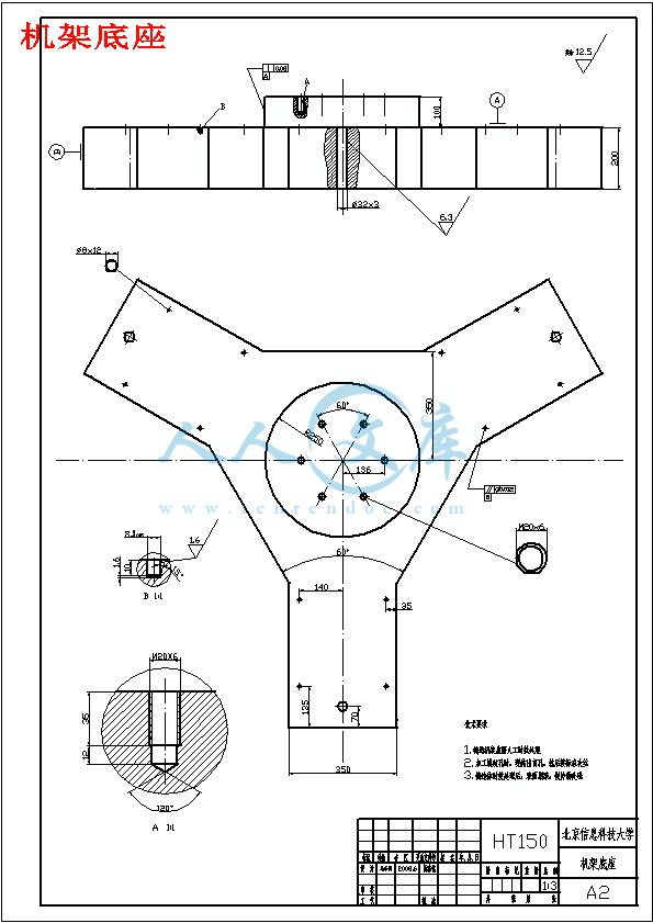
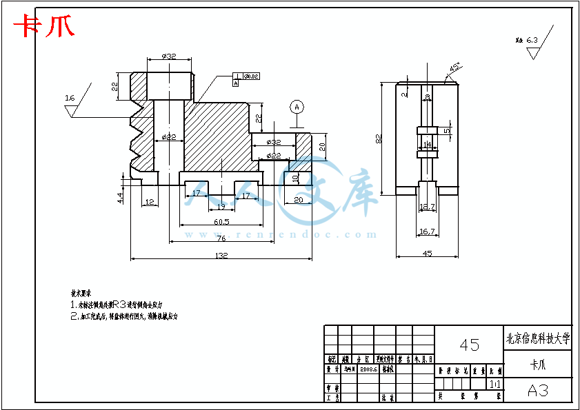
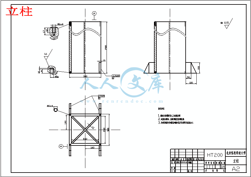
立柱.dwg
立柱.dwg

并联机床实验台总体结构设计【带solidworks三维】【8张机械CAD图纸+毕业论文】

收藏

资源目录
跳过导航链接。
压缩包内文档预览:
预览图
编号:435417    类型:共享资源    大小:7.64MB    格式:RAR    上传时间:2015-05-25 上传人:上*** IP属地:江苏
50
积分
关 键 词:
并联机床 实验总 试验 总体 结构设计 solidworks三维 机械 cad图纸 毕业论文 并联机床实验台
资源描述:

并联机床实验台总体结构设计
23页 15000字数+说明书+答辩稿+开题报告+外文翻译+8张CAD图纸【详情如下】
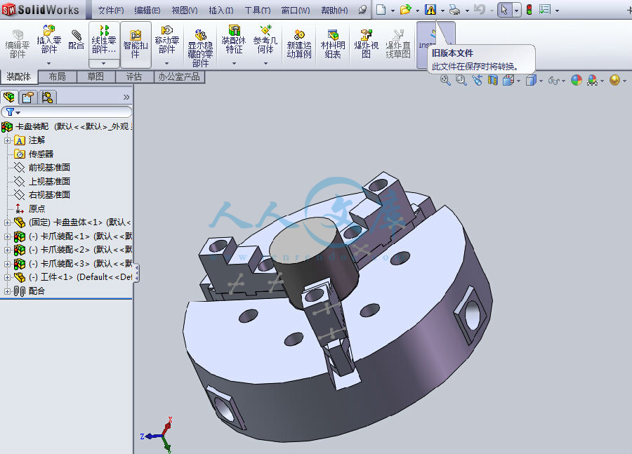
solidworks三维图.rar
三爪自定心卡盘.dwg
三维图.doc
主轴电机控制电路图.dwg
卡爪.dwg
卡爪底座.dwg
外文翻译--设计并联机床使用kinetostatic标准的表现.doc
并联机床实验台总体结构设计开题报告.doc
并联机床实验台总体结构设计答辩稿.ppt
并联机床实验台总体结构设计论文.doc
并联机床实验台总装图.dwg
摘要目录.doc
机架底座.dwg
机架装配图.dwg
立柱.dwg

摘要
随着信息技术的进步和全球化制造技术的进步,企业为了提高自身的竞争力,要求配置效率更高成本更低的加工设备,而传统机床在未来的加工业中会遇到难以克服的困难,例如在高速加工中(轨迹速度达到50m/min)和高效空间曲面加工及机床的通用性方面将无法满足现代加工技术的要求。因此探索和研究一种现代化机床具有十分重要的意义。
虚拟轴机床与传统的串联式数控机床相比具有很多优越性。传统数控机床各自由度是串联相接的,呈悬臂结构,且层叠嵌套致使传动链长,传动系统复杂,累计误差大,而精度低,成本昂贵,至今多数机床只是4轴联动,极少5轴。而虚拟轴机床的并联式加工中心结构特别简单,传动链极短,刚度大、质量轻、切削效率高、响应快,特别是很容易实现六轴联动,因而,能加工更复杂的三维曲面,且其加工精度和加工粗糙度都直接由控制程序来保证,因此,硬件成本低,而软件附加值高,是一种技术附加值极高的机电一体化产品。
此研究课题针对现今的机加工趋向,制定了设计一部并联机床实验台的任务,作者与合作人共同设计。其中的并联部分分配给了合作者,作者主要负责并联机床实验台的总体框架结构设计。
平台大致由并联机构——三根并联丝杠(驱动电机)、铸铁机架、装卡平台和电主轴以及弹簧铣夹头组成。
关键词:并联机构、虚轴加工、雅可比矩阵、正解算法
Abstract
With the progress of the information technology and the development of the global manufacturing techniques, enterprises require more efficient and lower cost machines by reason of enhancing their competitive ability. But conventional machine tools will encounter many difficulties which are hard to overcome in the future, for instance of high-speed machining ( path speed exceeding 50m/min)and high efficient space curved surfacing machining as well as flexibility of machines. Thus, it is very important to explore and study kind of modern machines.
Be compared to the normal numerical control machine tool, it has larger rigidity, stronger carrying capacity, smaller error, higher precision, smaller ratio of self-weight and load, better dynamical capacity, less investment of hardware, but stronger function of software. All of these show its high additional technical valve.
This research topic for the current trend of the processing machine, developed a design of a parallel machine test-bed task, which the Author co-design and a partner. Some of them parallel to the allocation of the partner, the author mainly responsible for the PMT test-bed framework of the overall structural design.
Platform from roughly parallel bodies - three parallel screw (motor driven), cast iron rack, with card platform and Spindle and milling chucks of spring.
Key words: parallel instruction, virtual axis processing, Jacobian Matrix, positive solution algorithm
目录
第1章 绪论 1
1.1课题背景与意义 1
1.2 并联机床发展历史及现状 2
1.3本文主要研究内容 5
第2章 重要零部件选型 6
2.1依照主轴功率确定电主轴型号 6
2.2 选择主轴下部刀具夹头 7
2.3选择工件的装卡方式 8
第3章 实验台支承部分及其连接的方案 11
3.1机架的设计方案 11
3.2铸造机架的材料及热处理 14
3.3机架的截面形状、壁厚及周边筋的布置 14
3.4立柱与底座的连接方式 16
3.5底座的造型 16
第4章 实验台驱动电路 17
4.1 电路布线方案 17
4.2 电路控制要求 17
4.3电路控制连线原理图 17
第5章 实验结果及三维建模 18
5.1 设计并联实验台结果 18
5.2 实验台solidworks建模 18
第6章总结与展望 19
参考文献 20
致  谢 20
并联机床的研究方向:
(1)并联机床组成原理的研究
研究并联机床自由度计算、运动副类型、支铰类型以及运动学分析、建模与仿真等问题。
(2)并联机床运动空间的研究
包括运动空间分析及仿真、可达工作空间求解(如数值求解法、球坐标搜索法等)、机床干涉计算及位置分析等。
(3)并联机床结构设计的研究
并联机床的结构设计包括很多内容,如机床的总体布局、安全机构设计、数控系统设计(包括数控平台建造、数控系统编程、数控加工过程仿真等)。
(4)并联机床刚度、精度、柔度、灵巧度的研究
并联机构封闭回路的特性,使并联机床较传统串联结构机床具有更高的刚度,但这个特性引起的耦合问题,相对的形成在动力分析上很大的困扰,因此对其研究应予以足够的重视。关于并联机床精度的研究仍是国际难题,包括机床系统硬件研究(及机床制造前精度设计和精度描述)和系统输出精度研究(及机床制造后输出数据处理和精度评价)。并联机床柔度的研究包括柔度分析、柔度评价指标及其在工作空间内的分布等方面。灵巧度主要研究灵巧度指标及其分布等。
(5)并联机床误差研究
包括误差分析、建模及误差精度保证、测量系统设计等问题。
(6)并联机床模块设计与创建
根据工件加工的空间型和平面型,相应地把并联机床分为空间型并联机床和平面型并联机床两大类。并联机床按功能和结构可分为以下几个功能模块:①执行模块;②机座模块(静平台模块);③动平台模块;④机架模块;⑤定位模块;⑥驱动模块;⑦控制和显示模块;⑧润滑与冷却模块。
(7)新型虚拟轴数控机床的研究
虚拟轴数控机床是“要用数学制造的机床”。因为这种机床的设计与运行要用到非常复杂的数学计算与推理。目前对于Stewart平台的理论研究已取得一些关键结论,还需进一步研究Stewart平台的综合分析,为虚拟轴数控机床的研制提供理论基础。
(8)并联机床控制的研究
包括高速、高精度的控制算法,刀具运动轨迹的直接控制、开放式数控系统等。虚拟轴机床的最大特点是机械结构简单而控制复杂,因此这方面的研究在并联机床的研究中具有举足轻重的作用。1.3 本文主要研究内容
给定主轴功率1kw,加工范围半径为350的半球体,主轴倾角±25°
以上述参数,自行设计并联机床总体零部件及装配方案。
涉及到电主轴、刀具夹头、装卡夹具、立柱、底座、电源走向、安装定位等的选用及其设计。
动力学问题
刚体动力学逆问题是并联机床动力分析、整机动态设计和控制器参数整定的理论基础。这类问题可归结为已知动平台的运动规律,求解铰内力和驱动力。相应的建模方法可采用几乎所有可以利用的力学原理,如牛顿-尤拉法、拉格朗日方程、虚功原理、凯恩方程等。由于极易由雅可比和海赛矩阵建立操作空间与关节空间速度和加速度的映射关系,并据此构造各运动构件的广义速度和广义惯性力,因此有理由认为,虚功(率)原理是首选的建模方法
动态性能是影响并联机床加工效率和加工精度的重要指标。并联机器人的动力性能评价完全可以沿用串联机器人的相应成果,即可用动态条件数、动态最小奇异值和动态可操作性椭球半轴长几何均值作为指标。与机器人不同,金属切削机床动态特性的优劣主要是基于对结构抗振性和切削稳定性的考虑。动态设计目标一般可归结为,提高整机单位重量的静刚度;通过质量和刚度合理匹配使得低阶主导模态的振动能量均衡;以及有效地降低刀具与工件间相对动柔度的最大负实部,以期改善抵抗切削颤振的能力。由此可见,机器人与机床二者间动态性能评价指标是存在一定差异的。事实上,前者没有计及对结构支撑子系统动态特性的影响,以及对工作性能的特殊要求;而后者未考虑运动部件惯性及刚度随位形变化的时变性和非线性。因此,深入探讨并联机床这类机构与结构耦合的、具有非定长和非线性特征的复杂机械系统动力学建模和整机动态设计方法,将是一项极富挑战性的工作。这项工作对于指导控制器参数整定,改善系统的动态品质也是极为重要的。第6章  总结与展望
此次课题《并联机床实验台》,在设计过程中,作者与合伙人遇到了许多的困难。相比较,并联机床机械结构简单,但并联机构的活动范围计算复杂,需要考虑的问题不计其数。在课题中难免有我们考虑不到的地方,望各位老师予以谅解。
传统机床的发展已有数百年的历史,而并联机床的出现才不过几年的时间,期望短期内一下子就能解决并联机床在理论和实践上的一系列难题是不现实的;同样,在并联机床发展过程中暂时碰到一些难题就认为并联机床没有前途、难以最终走向市场同样是不可取的。
并联机床的优点有许多,能够完成表面形状极其复杂的零件,加工形式类似于数控加工中心,而且具有高刚度、高精度等诸多优点。相比于普通铣床,加工性能大大提高。是机具发展前途的新型金属切削机床。
参考文献
1.黄真, 《空间机构学》, 北京:机械工业出版社, 1991
2. 熊有纶, 《机器人学》, 北京:机械工业出版设, 1989
3. 邵俊鹏, 《机床数控技术》, 哈尔滨工业大学出版社, 1990
4. 濮良贵, 《机械设计》, 高等教育出版社, 1989
5. 徐灏, 《机械设计手册》, 北京:机械工业出版社, 1991
6. 刘兴良, 《机器人和机械手控制系统》,北京:机械工业出版社,1984
7. 孔令富等, 《模型参数自摄影控制设计的一种方法》,信息与控制,1991,NO.4:29-32
8. 蒋松新, 《机器人及机器人学中的控制问题》 机器人, 1990,12(5):1-6
9. 梁崇高等, 《一种Stewart平台型机械手位移正解》,机械工程学报,1991,27 (2):26-30
10.胡汗才, 《单片机原理及其接口技术》,北京:清华大学出版社,1996
11.文福安,李静宜等,《并联机器人位置正解》, 机械科学与技术, NO.3,1993
12.黄真,孔令富,方跃法,《并联机器人机构学理论及控制》,北京:机械工业出版社,1997,2-4
13.陈文家,王宏光等,《并联机床的发展现状与展望》, 机电工程, 2001,18(4):5-8
14.Soumya Bhattacharys On the Optimum Design of Stewart Platform Type Parallel
Manipulators [J] Robotica.1995,13:133-1
15.Waldron K J., Raghavan M. and Roth B. Kinematics of a Hybrid serial-Parallel
Manipulation System. ASME J. of Dyn. Sys. Meas. And Cont.,1989,111,211-221
16. Sklar M. and Teasar D. Dynamic Analysis of Hybrid Serial Manipulator System
Containing Parallel Modules. J. Mech. Trans. and Aut. Des., 1988,109-11

内容简介:
机0405 11号 马吟川 指导老师:许宝杰THE DESIGN OF PARALLEL KINEMATIC MACHINETOOLS USING KINETOSTATIC PERFORMANCECRITERIA/ftp/arxiv/papers/0705/0705.1038.pdf1. INTRODUCTIONMost industrial machine tools have a serial kinematic architecture, which means thateach axis has to carry the following one, including its actuators and joints. High SpeedMachining highlights some drawbacks of such architectures: heavy moving parts requirefrom the machine structure high stiffness to limit bending problems that lower themachine accuracy, and limit the dynamic performances of the feed axes.That is why PKMs attract more and more researchers and companies, because theyare claimed to offer several advantages over their serial counterparts, like high structuralrigidity and high dynamic capacities. Indeed, the parallel kinematic arrangement of thelinks provides higher stiffness and lower moving masses that reduce inertia effects. Thus,PKMs have better dynamic performances. However, the design of a parallel kinematicmachine tool (PKMT) is a hard task that requires further research studies before wideindustrial use can be expected.Many criteria need to be taken into account in the design of a PKMT. We pay specialattention to the description of kinetostatic criteria that rely on the conditioning of theJacobian matrix of the mechanism. The organisation of this paper is as follows: nextsection introduces general remarks about PKMs, then is explained why PKMs can beinteresting alternative machine tool designs. Then are presented existing PKMTs. Anapplication to the design of a small-scale machine tool prototype developed at IRCCyNis presented at the end of this paper.2. ABOUT PARALLEL KINEMATIC MACHINES2.1. General RemarksThe first industrial application of PKMs was the Gough platform (Figure 1),designed in 1957 to test tyres1. PKMs have then been used for many years in flightsimulators and robotic applications2 because of their low moving mass and high dynamicperformances. Since the development of high speed machining, PKMTs have becomeinteresting alternative machine tool designs3, 4.Figure 1. The Gough platformIn a PKM, the tool is connected to the base through several kinematic chains or legsthat are mounted in parallel. The legs are generally made of either telescopic struts withfixed node points (Figure 2a), or fixed length struts with gliding node points (Figure 2b).Along with high-speed cuttings unceasing development, the traditional tandem type organization constructs the platform the structure rigidity and the traveling carriage high speed becomes the technological development gradually the bottleneck, but the parallel platform then becomes the best candidate object, but was opposite in the tandem engine bed, the parallel working platform had the following characteristic and the merit:(1) structure is simple, the price is low The engine bed mechanical spare part number is series connected constructs the platform to reduce largely, mainly by the ball bearing guide screw, the Hooke articulation, the ball articulation, the servo electrical machinery and so on common module is composed, these common modules may by the special factory production, thus this engine beds manufacture and the inventory cost are much lower than the same functions traditional engine bed, easy to assemble and the transporting. (2) structure rigidity is high Because used closeness structure (closed-loop structure) to enable it to have high rigid and the high speed merit, its structural load streamline was short, but shouldered decomposes pulls, the pressure also to withstand by six connecting rods, by materials mechanics viewpoint, when the external force was certain, the bracket quantitys stress and the distortion were biggest, the both sides inserted the (build-in) next best, came is again both sides Jan supports (simply-supported), next was the bearing two strength structure, what the stress and the distortion were smallest was the tensity two strength structure, therefore it had the high rigidity. Its rigidity load ratio is higher than traditional the numerically-controlled machine tool. (3) processing speed is high, the inertia is low If the structure withstands the strength will change the direction, (will be situated between tensity and pressure), two strength components will be most save the material the structure, but it will move to the moving parts weight to reduce to lowly and simultaneously will actuate by six actuating units, therefore machine very easy high speed, and will have the low inertia. (4) working accuracy is high Because it for the multiple spindle parallel organization composition, six expandable pole poles long alone has an effect to cutting tools position and the posture, thus does not have the traditional engine bed (i.e. connects engine bed) the geometrical error accumulation and the enlargement phenomenon, even also has the being uniform effect (averaging effect); It has the hot symmetrical structural design, therefore the thermal deformation is small; Therefore it has the high accuracy merit. (5) multi-purpose flexible Is convenient as a result of this engine bed organization simple control, easily according to processing object, but designs it the special purpose machine, simultaneously may also develop the general engine bed, with realizes the milling, boring, processings and so on grinding, but may also provide the essential measuring tool to compose it the measuring engine, realizes engine beds multi-purpose. This will bring the very big application and the market prospect, has the very broad application prospect in the national defense and the civil aspect. (6) service life is long Because the stress structure is reasonable, the moving part attrition is small, and does not have the guide rail, does not have the iron filings either the refrigerant enters the guide rail interior to cause it to scratch, the attrition or the corrosion phenomenon. (7) Stewart platform suits in the modular production Regarding the different machine scope, only need change the connecting rod length and the contact position, maintains also easily, does not need to carry on parts remaking and to adjust, only need the new organization parameter input. (8) transformation coordinate system is convenient Because does not have the entity coordinate system, the engine bed coordinate system and the work piece coordinate system transform depend on the software to complete completely, is convenient. When the Stewart platform applies in the engine bed and the robot, may reduce the static error (, because high rigidity), as well as dynamic error (because low inertia). But Stewart the platform inferiority lies in its working space to be small, and it has the singular point limit in the working space, but the serial operation platform, the controller meets time the singular point, accountant will figure out the actuation order which the drive is unable to achieve to create the ning error, but the Stewart platform will lose the support partial directions in the strange position the strength or moment of force ability, will be unable to complete the constant load object. Figure 2a. A bipod PKMFigure 2b. A biglide PKM2.2. SingularitiesThe singular configurations (also called singularities) of a PKM may appear insidethe workspace or at its boundaries. There are two types of singularities5. A configurationwhere a finite tool velocity requires infinite joint rates is called a serial singularity. Aconfiguration where the tool cannot resist any effort and in turn, becomes uncontrollable,is called a parallel singularity. Parallel singularities are particularly undesirable becausethey induce the following problems:- a high increase in forces in joints and links, that may damage the structure,- a decrease of the mechanism stiffness that can lead to uncontrolled motions of thetool though actuated joints are locked.Figures 3a and 3b show the singularities for the biglide mechanism of Fig. 2b. InFig. 3a, we have a serial singularity. The velocity amplification factor along the verticaldirection is null and the force amplification factor is infinite.Figure 3b shows a parallel singularity. The velocity amplification factor is infinitealong the vertical direction and the force amplification factor is close to zero. Note that ahigh velocity amplification factor is not necessarily desirable because the actuatorencoder resolution is amplified and thus the accuracy is lower.Figure 3a. A serial singularityFigure 3b. A parallel singularity2.3. Working and Assembly ModesA serial (resp. parallel) singularity is associated with a change of working mode6(resp. of assembly mode). For example, the biglide has four possible working modes fora given tool position (each leg node point can be to the left or to the right of theintermediate position corresponding to the serial singularity, Fig. 4a) and two assemblymodes for a given actuator joint input (the tool is above or below the horizontal linecorresponding to the parallel singularity, Fig. 4b). The choice of the assembly mode andof the working mode may influence significantly the behaviour of the mechanism5.Figure 4a. The four working modesFigure 4b. The two assembly modes3. PKMs AS ALTERNATIVE MACHINE TOOL DESIGNS3.1. Limitations of Serial Machine ToolsToday, newly designed machine tools benefit from technological improvements ofcomponents such as spindles, linear actuators, bearings. Most machine tools are based ona serial architecture (Figure 5), whose advantage is that input/output relations are simple.Nevertheless, heavy masses to be carried and moved by each axis limit the dynamicperformances, like feed rates or accelerations. That is why machine tools manufacturershave started being interested into PKMs since 1990.3.2. PKMs Potentialities for Machine Tool DesignThe low moving mass of PKMs and their good stiffness allow high feed rates (up to100 m/min) and accelerations (from 1 to 5g), which are the performances required byHigh Speed Machining.PKMs are said to be very accurate, which is not true in every case4, but anotheradvantage is that the struts only work in traction or compression. However, there aremany structural differences between serial and parallel machine tools, which makes ithard to strictly compare their performances.3.3. Problems with PKMsa) The workspace of a PKM has not a simple geometric shape, and its functionalvolume is reduced, compared to the space occupied by the machine7, as we can see onFig. 5Figure 5. Workspace sections of Tricept 805b) For a serial mechanism, the velocity and force transmission ratios are constant inthe workspace. For a parallel mechanism, in contrast, these ratios may vary significantlyin the workspace because the displacement of the tool is not linearly related to thedisplacement of the actuators. In some parts of the workspace, the maximal velocitiesand forces measured at the tool may differ significantly from the maximal velocities andforces that the actuators can produce. This is particularly true in the vicinity of THE DESIGN OF PKMT USING KINETOSTATIC PERFORMANCE CRITERIA 5singularities. At a singularity, the velocity, accuracy and force ratios reach extremevalues.c) Calibration of PKMs is quite complicated because of kinematic modelscomplexity8.4. EXISTING PKMT DESIGNSIn this section will be presented some existing PKMTs.4.1. Fully Parallel Machine ToolsWhat we call fully parallel machine tools are PKMs that have as many degrees offreedom as struts. On Fig. 7, we can see a 3-RPR fully parallel mechanism with threestruts. Each strut is made of a revolute joint, a prismatic actuated joint and a revolutejoint.Figure 6. 3-RPR fully parallel mechanismFully PKMT with six variable length struts are called hexapods. Hexapods areinspired by the Gough Platform. The first PKMT was the hexapod “Variax” fromGiddings and Lewis presented in 1994 at the IMTS in Chicago. Hexapods have sixdegrees of freedom. One more recent example is the CMW300, a hexapod head designedby the Compagnie Mcanique des Vosges (Figure 7).Figure 7. Hexapod CMW 300 (perso.wanadoo.fr/cmw.meca.6x/6AXES.htm)Fully parallel machine tools with fixed length struts can have three, four or six legs.The Urane SX (Figures8 and 13) from Renault Automation is a three leg machine,whose tool can only move along X, Y and Z axes, and its architecture is inspired fromthe Delta robot9, designed for pick and place applications. The Hexa M from Toyoda is aPKMT with six fixed length struts (Figure 9).Figure 8. Renault automation Urane SX (from “RenaultAutomation Magazine”, n 21, may 1999)Figure 9. Toyoda Hexa M (www.toyodakouki.co.jp)4.2. Other Kinds of PKMTThe Tricept 805 is a widely used PKMT with three variable length struts (Figures 5and 10). The Tricept 805 has a hybrid architecture: a two degrees of freedom wristserially mounted on a tripod architecture.Another non fully parallel MT is the Eclipse (Figure 11) from Sena Technology10, 11.The Eclipse is an overactuated PKM for rapid machining, capable of simultaneous fivefaces milling, as well as turning, thanks to the second spindle.Figure 10. Tricept 805 from Neos robotics()Figure 11. The Eclipse, from Sena Technology(macea.snu.ac.kr/eclipse/homepage.html)5. DESIGNING A PKMT5.1. A Global TaskGiven a set of needs, the most adequate machine will be designed through a set ofdesign parameters like the machine morphology (serial, parallel or hybrid kinematicstructure), the machine geometry (link dimensions, joint orientation and joint ranges), thetype of actuators (linear or rotative motor), the type of joints (prismatic or revolute), thenumber and the type of degrees of freedom, the task for which the machine is designed.These parameters must be defined using relevant design criteria.5.2. Kinetostatic Performance Criteria are Adequate for the Design of PKMTsThe only way to cope with problems due to singularities is to integrate kinetostaticperformance criteria in the design process of a PKMT. Kinetostatic performance criteriaevaluate the ability of a mechanism to transmit forces or velocities from the actuators tothe tool. These kinetostatic performance criteria must be able to guaranty minimumstiffness, accuracy and velocity performances along every direction throughout the workspace of the PKMT.To reach this goal, we use two complementary criteria: the conditioning of theJacobian matrix J of the PKMT, called conditioning index, and the manipulabilityellipsoid associated with J12. The Jacobian matrix J relates the joint rates to the toolvelocities. It also relates the static tool efforts to the actuator efforts. The conditioningindex is defined as the ratio between the highest and the smallest eigenvalue of J. Theconditioning index varies from 1 to infinity. At a singularity, the index is infinity. It is 1at another special configuration called isotropic configuration. At this configuration, thetool velocity and stiffness are equal in all directions. The conditioning index measuresthe uniformity of the distribution of the velocities and efforts around one givenconfiguration but it does not inform about the magnitude of the velocity amplification oreffort factors.The manipulability ellipsoid is defined from the matrix (J JT)-1. The principal axes ofthe ellipsoid are defined by the eigenvectors of (J JT)-1 and the lengths of the principalaxes are the square roots of the eigenvalues of (J JT)-1. The eigenvalues are associatedwith the velocity (or force) amplification factors along the principal axes of themanipulability ellipsoid.These criteria are used in Wenger13, to optimize the workspace shape and theperformances uniformity of the Orthoglide, a three degree of freedom PKM dedicated tomilling applications (Figure 12).Figure 12. A section of Orthoglides optimised workspace5.3. Technical ProblemsIf the struts of the PKMT are made with ballscrews, the PKMT accuracy may sufferfrom struts warping due to heating caused by frictions generated by ballscrews. Thisproblem is met by hexapods designers that use ballscrews. Thus, besides manufacturinginaccuracies, the calibration of a PKMT will have to take into account dimensionsvariations due to dilatation. A good thermal evacuation can minimise the effects ofheating.In case PKMT actuators are linear actuators, magnetic pollution has to be taken intoaccount so that chips clearing out is not obstructed. One technique, used by RenaultAutomation for the Urane SX, is to isolate the tool from the mechanism.At last, choosing fixed length or variable length struts influence the behaviour of themachine. Actuators have to be mounted on the struts in case of variable length struts,which increases moved masses. Fixed length struts do not have this problem, andfurthermore allow the use of linear actuators, that bring high dynamic performances.6. CONCLUSIONSThe aim of this article was to introduce a few criteria for the design of PKMTs, whichmay become interesting alternatives for High Speed Machining, especially in the millingof large parts made of hard material, or for serial manufacturing operations onaeronautical parts.Kinetostatic criteria seem to be well adapted to the design of PKMTs, particularly forthe kinematic design and for the optimisation of the workspace shape, with regard toperformances uniformity.The kinetostatic criteria have been used for the design of the Orthoglide, a three-axisPKMT developed at IRCCyN. A small scale prototype is under development. A five-axisPKMT will be derived from the Orthoglide.设计并联机床使用kinetostatic标准的表现/ftp/arxiv/papers/0705/0705.1038.pdf1 介绍多数工业机床有一个串行运动学架构,这意味着每个轴进行下列工作时,包括其执行机构和联接点高速加工突出了一些弊端,例如架构:较重的运动部件需要从机械结构高刚度,以限制弯曲问题,即降低机床精度,并限制动态表现的曲线。这就是为什么并联机床吸引了越来越多的研究人员和公司,因为它们据称提供了单独的优势,如高结构刚度和高动态的能力。事实上,并联安排的联系,可提供更高的刚度和较低的误差,减少惯性的影响。因此,并联机床有更好的动态性能。然而,设计一个并联机床是一个艰巨的任务,在进一步的研究之前,广泛地在工业用途中的调研,是必不可少的。许多标准要考虑到在设计一个并联机床。我们要特别注意描述并联机床标准依赖于现有的雅可比矩阵的机制。该组织的这份文件具体内容如下:未来介绍总论约并联机床,那就是解释了为什么并联机床是不可替代机床的设计。一个设计中的应用了一次小规模的机床样机研制irccyn。2 关于并联机床2.1 总论第一次工业应用并联机床是The Gough平台(图1 ) 设计于1957年,以测试tyres1 。并联机床当时已使用多年,在飞行模拟器和机器人applications2因为他们的低移动质量和高动态表演。由于发展的高速切削加工,并联机床已成为有趣的替代机床。图1 The Gough platform随着高速切削的不断发展,传统串联式机构构造平台的结构刚性与移动台高速化逐渐成为技术发展的瓶颈,而并联式平台便成为最佳的候选对象,而相对于串联式机床来说,并联式工作平台具有如下特点和优点:(1) 结构简单、价格低 机床机械零部件数目较串联构造平台大幅减少,主要由滚珠丝杠、虎克铰、球铰、伺服电机等通用组件组成,这些通用组件可由专门厂家生产,因而本机床的制造和库存成本比相同功能的传统机床低得多,容易组装和搬运。(2) 结构刚度高 由于采用了封闭性的结构(closed-loop structure)使其具有高刚性和高速化的优点,其结构负荷流线短,而负荷分解的拉、压力由六只连杆同时承受,以材料力学的观点来说,在外力一定时,悬臂量的应力与变形都最大,两端插入(build-in)次之,再来是两端简支撑(simply-supported),其次是受压的二力结构,应力与变形都最小的是受张力的二力结构,故其拥有高刚性。其刚度重量比高于传统的数控机床。(3) 加工速度高,惯性低如果结构所承受的力会改变方向,(介于张力与压力之间),两力构件将会是最节省材料的结构,而它的移动件重量减至最低且同时由六个致动器驱动,因此机器很容易高速化,且拥有低惯性。(4) 加工精度高由于其为多轴并联机构组成,六个可伸缩杆杆长都单独对刀具的位置和姿态起作用,因而不存在传统机床(即串联机床)的几何误差累积和放大的现象,甚至还有平均化效果(averaging effect);其拥有热对称性结构设计,因此热变形较小;故它具有高精度的优点。(5) 多功能灵活性强由于该机床机构简单控制方便,较容易根据加工对象而将其设计成专用机床,同时也可以将之开发成通用机床,用以实现铣削、镗削、磨削等加工,还可以配备必要的测量工具把它组成测量机,以实现机床的多功能。这将会带来很大的应用和市场前景,在国防和民用方面都有着十分广阔的应用前景。(6) 使用寿命长由于受力结构合理,运动部件磨损小,且没有导轨,不存在铁屑或冷却液进入导轨内部而导致其划伤、磨损或锈蚀现象。(7) Stewart平台适合于模块化生产对于不同的机器加工范围,只需改变连杆长度和接点位置,维护也容易,无须进行机件的再制和调整,只需将新的机构参数输入。(8) 变换座标系方便由于没有实体座标系,机床座标系与工件座标系的转换全部靠软件完成,非常方便。Stewart平台应用于机床与机器人时,可以降低静态误差(因为高刚性),以及动态误差(因为低惯量)。而Stewart平台的劣势在于其工作空间较小,且其在工作空间上有着奇异点的限制,而串联工作平台,控制器遇到奇异点时,将会计算出驱动装置无法达成的驱动命令而造成控制误差,但Stewart平台在奇异位置会失去支撑部分方向的力或力矩的能力,无法完成固定负载对象。在并联机床,工具是以底座作为支撑做伸缩性运动,下图为伸缩运动简图。一般均作伸缩臂的同固定结点(图2A )条,或固定长度的伸缩臂与滑动结点(图2b )条。图2a A bipod PKM图2b A biglide PKM22 奇点奇异的配置(也称为奇点)的一个并联机床可能出现内工作空间或在其边界。有两种类型的奇点 。一个配置叫做有限速率,在结点处需要极大的速率,是所谓的一个序列奇异性。配置工具不能抗拒任何阻力,并且会转变得无法控制, 所谓平行奇异。平行的奇异尤其不可取因为他们导致以下几个问题: 结点处受力过高,这可能会损害结构,减少了该机制的刚度,这会导致无节制的运动规律工具虽然驱动关节锁死。图3A及3B及第查看奇异为biglide机制图。图2B在图3 A ,我们有一个串行奇异。速度放大系数沿垂直方向是无效的力量放大系数是无限的。 图3B及第显示一个平行的奇异性。速度放大系数是无穷,沿着垂直方向和部队放大系数是接近于零。注:一高流速放大系数并不一定是可取的,因为舵机编码器分辨率扩增,因此,准确度较低。图3a. A serial singularity图 3b. A parallel singularity2.3 工作和装配方式一个序列(或平行)的奇异性,是与转变工作模式6(或者装配模式)。举例来说, biglide有四种可能的工作模式某一特定工具的位置(每个结点的,可以向左边或到右边的中间位置相对应的串行奇异,在图4A )及两项装配模式,为某个结点处进行输入(该工具是高于或低于此水平线对应平行的奇异性,图4 )。选择装配模式和该工作模式,可明显影响的行为机制。图 4a. The four working modes图 4b. The two assembly modes3 并联机床作为替代机床设计31局限性串行机床今天,新设计的机床受益于技术的改进部件,如主轴,线性传动,轴承。多数机床是基于串行架构
温馨提示:
1: 本站所有资源如无特殊说明,都需要本地电脑安装OFFICE2007和PDF阅读器。图纸软件为CAD,CAXA,PROE,UG,SolidWorks等.压缩文件请下载最新的WinRAR软件解压。
2: 本站的文档不包含任何第三方提供的附件图纸等,如果需要附件,请联系上传者。文件的所有权益归上传用户所有。
3.本站RAR压缩包中若带图纸,网页内容里面会有图纸预览,若没有图纸预览就没有图纸。
4. 未经权益所有人同意不得将文件中的内容挪作商业或盈利用途。
5. 人人文库网仅提供信息存储空间,仅对用户上传内容的表现方式做保护处理,对用户上传分享的文档内容本身不做任何修改或编辑,并不能对任何下载内容负责。
6. 下载文件中如有侵权或不适当内容,请与我们联系,我们立即纠正。
7. 本站不保证下载资源的准确性、安全性和完整性, 同时也不承担用户因使用这些下载资源对自己和他人造成任何形式的伤害或损失。
提示  人人文库网所有资源均是用户自行上传分享,仅供网友学习交流,未经上传用户书面授权,请勿作他用。
关于本文
本文标题:并联机床实验台总体结构设计【带solidworks三维】【8张机械CAD图纸+毕业论文】
链接地址:https://www.renrendoc.com/p-435417.html

官方联系方式

2:不支持迅雷下载,请使用浏览器下载   
3:不支持QQ浏览器下载,请用其他浏览器   
4:下载后的文档和图纸-无水印   
5:文档经过压缩,下载后原文更清晰   
关于我们 - 网站声明 - 网站地图 - 资源地图 - 友情链接 - 网站客服 - 联系我们

网站客服QQ:2881952447     

copyright@ 2020-2025  renrendoc.com 人人文库版权所有   联系电话:400-852-1180

备案号:蜀ICP备2022000484号-2       经营许可证: 川B2-20220663       公网安备川公网安备: 51019002004831号

本站为文档C2C交易模式,即用户上传的文档直接被用户下载,本站只是中间服务平台,本站所有文档下载所得的收益归上传人(含作者)所有。人人文库网仅提供信息存储空间,仅对用户上传内容的表现方式做保护处理,对上载内容本身不做任何修改或编辑。若文档所含内容侵犯了您的版权或隐私,请立即通知人人文库网,我们立即给予删除!