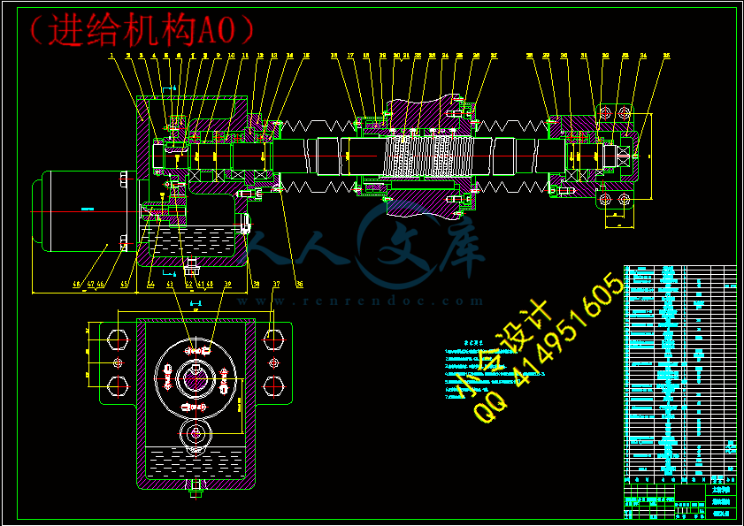
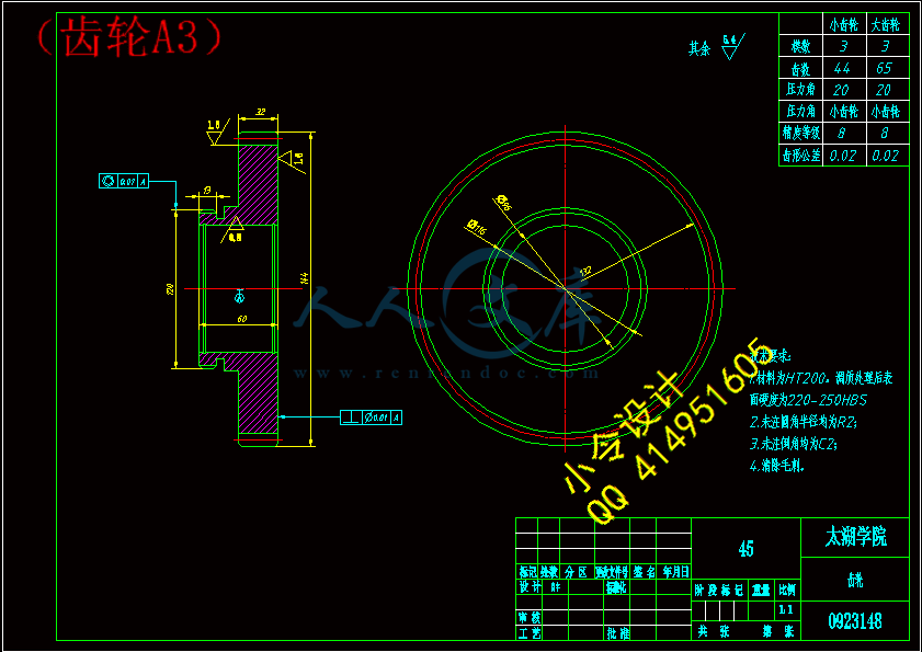
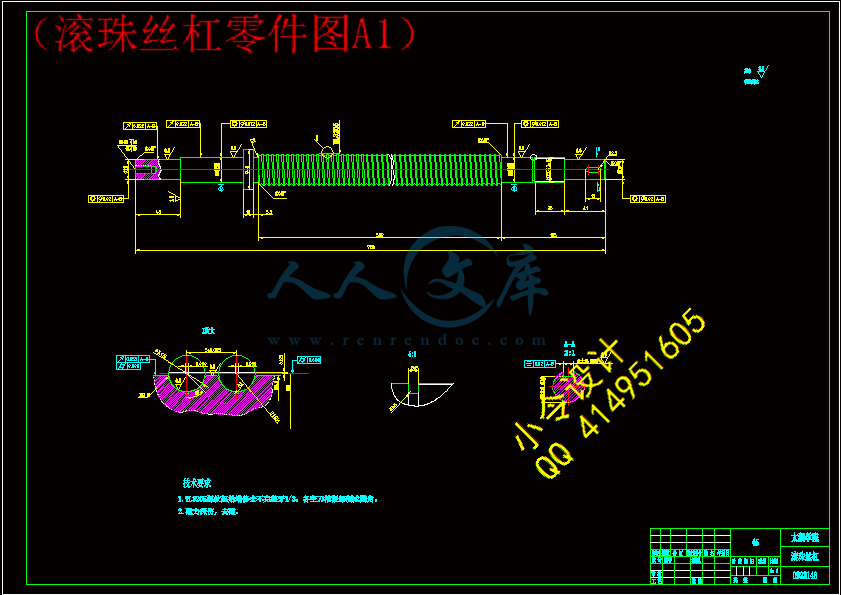
(齿轮A3).dwg
(齿轮A3).dwg

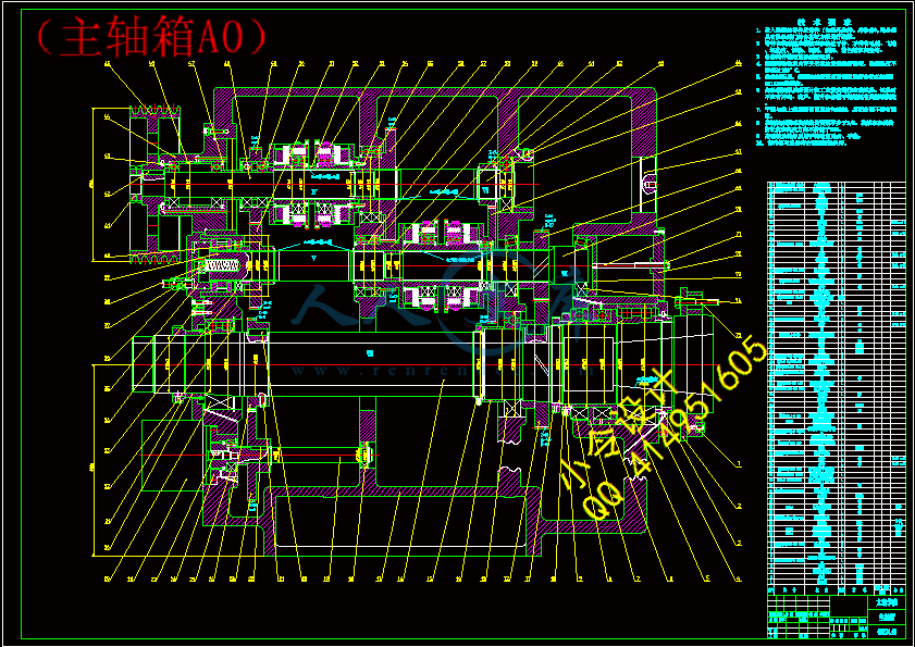
CK6163型数控机床设计【7张CAD图纸+毕业论文】

收藏

压缩包内文档预览:
预览图
编号:435863    类型:共享资源    大小:1.84MB    格式:RAR    上传时间:2015-05-26 上传人:好资料QQ****51605 IP属地:江苏
45
积分
关 键 词:
ck6163 数控机床 设计
资源描述:

【温馨提示】 购买原稿文件请充值后自助下载。

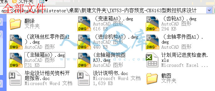
[全部文件] 那张截图中的文件为本资料所有内容,下载后即可获得。


预览截图请勿抄袭,原稿文件完整清晰,无水印,可编辑。

有疑问可以咨询QQ:414951605或1304139763


摘  要

数控技术是当今先进制造技术和装备最核心的技术,机械制造业的竞争,其实质是数控技术的竞争。从目前世界上数控技术及其装备发展的趋势来看,其主要研究热点有以下几个方面:1.功能发展方向;2.结构体系发展方向;3.高速、高效、高精度、高可靠性发展方向;

CK6163型数控机床是开环式的数字程序控制车床。能进行内外圆柱面、圆锥面、圆弧面、圆柱螺纹和圆锥螺纹等加工。机床主轴的启动、停止和变速,纵向和横向进给运动的行程和速度,刀具的变换和冷却,都可以自动控制。并具有直线、锥度、直螺纹和锥螺纹等自动循环机能。

CK6163型数控机床有床头箱、变速箱、进给机构、刀架、控制箱等组成。床头箱中由操纵油缸中的活塞杆带动拔叉来控制双向内齿离合器的接通或放松,使主轴实现四级变速。主运动采用分离传动从而使变速箱实现四级变速。进给机构由床鞍纵向进给电液脉冲马达、滚珠丝杠副和中间传动齿轮副组成。


关键词:数控技术;床头箱;变速箱;进给机构;滚珠丝杠;


Abstract

Numerical control technology is the core technology of the advanced manufacturing technology and equipment, machinery manufacturing competition, and its essence is the competition of numerical control technology.From the numerical control technology and equipment development trend, its main research focus has the following several aspects:1 .The direction of function development;2. The direction of structural system development;3. High speed, high efficiency, high precision and high reliability;

CK6163 numerical controlled machine tool is the open loop type digital program controlled lathe. To inside and outside the cylinder, cone surface, such as processing arc face, straight thread and taper thread. Start, stop, and variable speed machine tool spindle, longitudinal and transverse feed motion of stroke and speed, transformation and the cooling of a tool, can be controlled automatically. And with a straight line, taper, straight thread and automatic cycle function of taper thread and so on.

CK6163 numerical controlled machine tool headstock, transmission, feeding mechanism, tool carriage, control box, etc. Bedside box by manipulating the oil cylinder piston rod to control the bidirectional drive fork of the internal tooth clutch connected or relax, for level 4 speed of spindle. Separation is used in the main movement transmission so that realize four speed gearbox. Feed mechanism by the bed saddle longitudinal feed electric hydraulic pulse motor, ball screw pair and the intermediate transmission gears.


Key  words:  Numerical control technology; Bedside cabinet; Gearbox; Feed mechanism;

Ball screw;


目  录

摘  要III

AbstractIV

目  录V

1 绪论1

 1.1本课题的研究内容和意义1

 1.2国内外的发展概况1

 1.3本课题应达到的要求2

2 总体方案3

 2.1 CK6163的现状和发展3

 2.2 CK6163卧式车床的总体方案3

3 主轴箱的设计4

 3.1 主轴箱的运动设计4

   3.1.1 已知条件4

   3.1.2 结构分析式4

   3.1.3 拟定转速图4

   3.1.4 确定转速图5

   3.1.5 确定各变速组传动副齿数6

 3.2 齿轮传动设计7

   3.2.1 渐开线直齿轮设计7

   3.2.2 斜齿轮设计8

 3.3 主轴传动设计11

   3.3.1 确定主轴最小直径11

   3.3.2 主轴最佳跨距的确定11

   3.3.3 主轴刚度的校核12

 3.4 带传动设计12

 3.5 滚珠螺母丝杠14

   3.5.1 滚珠丝杠副的种类与结构14

   3.5.2 内循环式14

   3.5.3 外循环式14

   3.5.4 滚珠丝杠副的结构参数15

   3.5.5 滚珠丝杠副的结构特点15

   3.5.6 滚珠丝杠副的安装支撑方式15

4 变速箱的设计17

 4.1 运动部分计算17

   4.1.1 参数确定的步骤和方法17

 4.2 传动设计18

  4.2.1 传动结构式、结构网的选择18

   4.2.2 主传动顺序的安排19

   4.2.3 传动系统的扩大顺序的安排19

   4.2.4传动组的变速范围的极限植19

   4.2.5 最后扩大传动组的选择20

 4.3 转速图的拟定20

   4.3.1 主电机的选定20

    4.3.2 双速和多速电机的应用20

    4.3.3 电机的安装和外形20

    4.3.4 常用电机的资料21

    4.3.5 齿轮传动比的限制21

 4.4 带轮传动部分的设计21

    4.4.1 带轮直径确定的方法、步骤21

    4.4.2 三角带传动的计算21

    4.4.3 选择三角带的型号21

    4.4.4 确定带轮的计算直径D1、D222

 4.5 齿轮传动部分的设计24

 4.6 电磁离合器的选择28

    4.6.1 按扭距选择28

    4.6.2 步骤28

 4.7 轴的设计计算29

    4.7.1 轴Ⅱ的设计计算29

    4.7.2 轴Ⅶ的设计计算29

 4.8 纵向进给系统的设计计算34

    4.8.1 纵向进给系统的设计34

    4.8.2 纵向进给系统的设计计算34

5 结论与展望40

 5.1 结论40

 5.2 不足之处及未来展望40

致谢41

参 考 文 献42


1 绪论

1.1本课题的研究内容和意义

数控机床通常由控制系统,伺服系统,检测系统,机械传动及其他辅助系统组成。数控机床相比较于普通机床有以下特点:(1)加工精度高,拥有稳定加工质量;(2)拥有多坐标的联动,能加工较为复杂的工件;(3)加工时间短;(4)生产效率高;(5)自动化程度高,减轻劳动强度;

数控机床的控制方式有很多种,主要分为开环控制,闭环控制和半闭环控制。开环控制系统没有反馈装置,系统不会计算误差,精度不高,但属于经济型;闭环控制系统和半闭环控制系统都装有反馈装置,他们区别在于反馈检测装置安装位置不同,闭环控制系统的反馈装置在工作台上,而半闭环控制系统的反馈装置在轴端或者丝杆上。本次研究的CK6263型数控机床的控制就属于开环控制系统。

CK6163型数控车床,是车床中应用最广泛、最典型的一种数控车床。该机床是开环式的数字控制车床。能进行内外圆柱面、圆锥面、圆弧面、圆柱螺纹和圆锥螺纹等加工。机床主轴的起动、停止和变速,纵向和横向进给运动的行程和速度,刀具的变换和冷却,都可以自动控制。并具有直线、锥度、直螺纹和锥螺纹等自动循环功能。在该机床中采用液压卡盘、液压尾座、快换刀架和机床外对刀装置。该机床使用于加工形状复杂的中小批量的零件。

数控机床的主传动方式分为集中传动方式和分离传动方式。集中传动是指主传动和变速传动在同一个主轴箱内的传动方式,其优点在于结构紧凑,便于实现集中操作,安装调整方便,主要用于普通精度的大中型机床;分离传动是指主传动的大部分传动和变速传动安装于远离主轴的单独变速箱内,通过带传动将运动传到主轴箱的传动方式,其优点在于变速箱内各传动件所产生的的振动和热能不直接传给或少传给主轴,有利于提高主轴工作精度,主要运用于对精度要求高的机床。

CK6163型数控机床就是采用了分离传动,来提高工作精度。

1.2国内外的发展概况

数控技术及装备是发展新兴高新技术产业和尖端工业的使能技术和最基本的装备。世界各国信息产业、生物产业、航空、航天等国防工业广泛采用数控技术,以提高制造能力和水平,提高对市场的适应能力和竞争能力。工业发达国家还将数控技术及数控装备列为国家的战略物资,不仅大力发展自己的数控技术及其产业,而且在"高精尖"数控关键技术和装备方面对我国实行封锁和限制政策。因此大力发展以数控技术为核心的先进制造技术已成为世界各发达国家加速经济发展、提高综合国力和国家地位的重要途径。

目前,欧、美、日等工业化国家已经先后完成数控机床产业化进程,而我国是从20世纪80年代才开始起步,处于发展阶段。国内本土数控机床企业大多处于“粗放型”阶段,在产品设计水平、质量、精度、性能等方面与国外先进水平相比落后了5-10年;在高、精、尖技术方面的差距则达到了10-15年。同时中国在应用技术及技术集成方面的能力也还比较低,相关的技术规范和标准的研究制定相对滞后,国产的数控机床还没有形成品牌效应。同时,中国的数控机床产业目前还缺少完善的技术培训、服务网络等支撑体系,市


场营销能力和经营管理水平也不高。更重要原因是缺乏自主创新能力,完全拥有自主知识产权的数控系统少之又少,制约了数控机床产业的发展。

十二五期间我国将持续投入,且力度加大,力争通过10-15年的时间,实现由机床工具生产大国向机床工具强国转变,实现国产中高档数控机床在国内市场占有主导地位等一系列中长期目标。

在数控机床制造方面,德国和日本一直处于领先地位,德国是老牌工业强国,其锻压机械种类齐全,基本上每一种锻压设备都有代表世界最先进水平的产品,比如通快的钣金成形机床、舒勒的大型覆盖件压力机、多工位压力机和冲压自动生产线、米勒万家顿的电动螺旋压力机、奥姆科的热模锻压力机、哈森克勒佛的离合器式螺旋压力机、拉斯科的锻锤、辛北尔康普的大型液压机、瓦格纳-班宁的碾环机、雷菲尔德的旋压机、FELSS的旋锻机等等的锻压机械。日本的锻压机械和德国一样,在世界上居于领先地位,尽管在大型和重型锻压设备方面不如德国,但在数控锻压机械,尤其在伺服驱动压力机方面具有很高的技术水平。而在我国沈阳、大连两市已基本成为全国数控车床、加工中心的中央综治委开发基地;在长江三角洲地区已成为数控磨床、电加工机床、板材加工设备、等的主要生产基地。

1.3本课题应达到的要求

本课题主要研究CK6163型数控机床的设计,主要设计主轴箱和变速箱,还有涉及到进给机构的设计,以及一些零部件的设计。而主要问题是:相关文献资料的缺乏,对一些结构设计部分的具体设计指导,以及制图软件的高级运用技巧。

内容简介:
中文译文计算机辅助制造计算机辅助制造一词涵盖了信息处理、生产决策、及生产加工等诸多领域,给CAM下一个简单的定义极为困难。D.Kochan针对CAM的多样性和广泛的应用范围,给CAM下了一个非常合适的定义。CAM可定义为计算机辅助生产准备,包括决策、工艺和作业计划、软件设计技术、人工智能、用不同类型的自动机床(如数控机床、数控加工中心、数控加工单元、数控柔性制造系统),以及不同种类的实现方法(CNC计算机数控技术、DNC群控技术)。由于CAM有如此广泛的使用范围。认识CAM更好的方法是通过CAM技术。CAM技术覆盖了群控技术、射干难产数据库、自动化、公差等。图22-1所示的是CAM的一般框架结构。生产中计算机的基本职能就是获取和处理与大量业务有关的数据,这些业务在企业内各个部门中连续不断地发生。CAM最初的研究是1953年麻省理工学院(MIT)对机床数字控制的研究。在MIT,出现懒得编程语言即自动化编程工具(APT),它是后来进一步发展的基本工具。当前CAM涉及到的功能如下:数控技术 (NC)计算数字控制 (CNC)计算机控制输送系统计算机加工控制过程计算机辅助工艺过程监控计算机辅助夹具设计计算机辅助刀具设计计算机辅助公差分析计算机辅助成本估算物料需求规划 (MRP)计算机辅助加工工艺(CAPP)计算机化的可加工数据系统加工资源规划 (MRP)计算机数控技术数控(NC)是可编程自动化的一种表现形式,它以数字、字母和其他符号来控制加工设备。这些数字、字母、符号按适当的格式编码,形成用于某一工件或任务的加工程序。当任务改变了,某一工件的加工程序也随之改变。这种改变程序的能力使得NC适合于西欧挨批量生产,更新程序要比大量改变加工设备要容易得多。数控原理首先用在铣削加工中,然后用在车削加工中、火焰切割、钻削和磨削之中,数控技术越来越多地用在其他的机加工过程中,如成形加工(精密锻造,液压等)、雕刻或激光切割。目前数控技术相对成熟,许多数控设备具有多种加工功能,如铣削中心可以进行垂直和水平铣削、钻削、镗削、铰孔、插削、成形和车削等加工过程,当然,在配有大容量的自动化刀库后,CNC机床的功能将更加丰富。可编程控制器可编程控制器(PLC)广泛地用于计算机辅助制造中。事实上,PLC用在企业有自动化要求的每个环节上,PLC是电子工业快速发展的代表。从PLC诞生之起,就成为许多生产规划中的重要辅助设备,而以往是依靠机电控制系统的。PLC是一个硬件装置,用来实现以前继电器完成的逻辑功能。大多数PLC的设计与计算机的设计相似。PLC基本上由固态数字逻辑元件组合而成,用于进行逻辑判断和提供输出。可编程控制器可用来运行和控制生产加工设备及其他机器设备。计算机辅助物料处理物料处理(MH)是体现工厂或公司运营效率的非常重要因素,一个高效的MH系统有助于减少等待时间,它甚至有助于提高整个加工过程的安全性或效率。Cabbert和Brown指出,生产成本的60%用于物料处理。事实也证明大多数离散加工的产品在加工过程中有90%的时间用于物料处理及储存。由于MH在生产总成本中占有如此多的比例,显然减少产品的物料处理时间一定能降低产品成本。帮助降低这些成本的途径之一是应用计算机做无聊处理的部分工作。目前,有许多物料处理设备可供购买。并有许多种MH手段可供使用。一种手段就是采用计算机数据库来记录MH设备清单和输入使用者因素植。计算机获取使用者的需求水平、轻重缓急、各自的信誉度及拥有的MH设备完成任务的可行性,并且提供设备的种类,待使用者从中挑选适合的MH设备品种和模块。生产过程计算机监控及故障诊断在计算机监控及故障诊断系统中,监控的目的是发现错误,而诊断的目标包括故障定位和确认。监控和诊断都应出现在各级监控体系中。几乎所有监控和诊断系统都要达到如下的基本要求:(1) 具有测量和处理相当多的模拟和数字信号的能力。(2) 具有测量信号并进行深层次的预处理能力,包括统计分析和频率分析的能力。(3) 具有复杂多参数的决策能力。(4) 具有模块化、可延展性和可重性的结构。(5) 所有功能的可编程能力。(6) 有标准的软件/硬件双向接口与CNC/DNC控制器相连。对诊断系统的要求如下:(1) 当出现差错时,系统应能方便地提供关于该机差错的相关知识,使得甚至是对加工过程不熟悉的工人能知道差错发生在何处。(2) 差错的影响结果在系统中能方便得到,因而能估计到已知差错后续生产影响的严重程度。(3) 用户该有独自修复差错的可能性,即修复指令以一种合适的形式让用户能够得到。(4) 该专家系统能由那些先前在计算机方面没有经验的雇员来操作。(5) 经过短期培训之后,系统可由运行设备的雇员来维护,这样,专家工程师就没有必要时刻在现场。根据在制造系统中所处的位置和具备的功能,监控诊断系统可有三种主要类型:(1) 独立监控子系统:它仅从上级控制层获得包含环境或条件描述的信息,为所有监控处理单元提供测量、处理、分类及干预所需的指令、参数或配置。(2) 辅助监控子系统:仅仅完成测量和处理任务并向系统控制层传输分类和干预信息。(3) 半独立监控系统:在同层中表现出独立的简单快捷的监控功能,并将复杂的分类和干预信息转交给上层。理想的计算机监控和诊断系统可以概括为是一个专家不在现场即可使用的系统,例如当专家休假、休息,或者公司要求有三班制,其中底三班没什么人的情况下能使用的系统。(A)计算机辅助设计计算机辅助设计可定义为用计算机来通过有效的创造、修改,或证明零件的几何模型来辅助工程设计过程。CAD是最普遍的人机交流的综合系统的一种应用。工程设计的对象被储存和表现为几何模型的形式。几何学的模型和发展物体的几何学的数学描述与CAD系统的使用有关。数学的描述叫做一个模型。有三种模型形式(线框架模型,表面模型和实体模型),它们被普遍用来表现一个实际的物体。线框架模型也被叫做边缘顶点或枝条轮廓模型,是定义零件计算机模型的最简单和最常用的方法。表面模型可能被构造在要使用一个表面面貌的大部分时。实体模型能比枝条面的构造更好地记录计算机数学从面跳跃到体积。结果,它可能用来计算零件的大部分性能,就是要求经常进行工程分析的如有限元分析,动力学分析,和大部分压力转移的检查。CAD模型也被分成二维(2D)模型,二又二分之一(2/1)模型,三维(3D)模型。一个2D模型表现一个平坦的部份,而一个 3D立体模型则提供零件整体的形状。一个2/1模型可以用来描述不变的没有边面部分的断面。2/1模型的大部分优点就是给一些3D立体模型的一部份一个大概的意思,而没有产生完整 3D立体模型数据库的必要。在一部分选择替代发展后,许多工程分析必须经常被定义为设计过程的一部分。这个分析可以是压力拉力的计算,动力学分析,有限元模拟实验等。一些在CAD系统的典型软件上提供一些大部分性能分析和有限元分析的例子。大部分性能分析包含一个实体的外貌如它的体积,空间表面,重量和重心。有限元分析在大部分CAD系统中有效地辅助压力转移,拉压应力分析,动力学分析,和各种工程计算。现在,各种CAD系统可以自动地产生2D或3D有限元分析紧密配合这就是有限元分析的实质。现实中的问题是,CAD系统的发展是成熟的。尽管如此,考虑到CAD和CAPP的相互配合工作,许多问题仍然存在。主要的问题是几何模型的转变,严格地说是,几何模型的描述,从CAD到CAPP。例如,最简单的2D形式中,最初制图明细表可以认为是工程画法,但是一个小的项比如尺寸可以用不同的方法定义。不同的设计系统用不同的技术把线组合成面。结果,在用IGES在不同的系统中间进行数据捕捉时出现了很多问题。在三维中,这些问题更加突出因为许多整理表面和空间曲线的方法的不协调。一些另外的尝试,比如分界线描述的接近和实体结构模型上的接近在这些创造中被认为是从最初的模型中得到特殊关系。不要提供任何可以和在局部信息的基础上得出的机械加工相结合的警告信息。然而,在这一个区域中做了很多的努力,而且许多方法已经与CAD一起提供到CAPP的接口中。(B) 计算机辅助工艺规程计划CAPP被定义为使用计算机编制辅助加工工艺规程计划工作的功能。辅助加工的水平程度依赖于不同的工作人员编制执行不同的加工工艺规程计划。对于将会用手被程序计划者构造的程序计划为储藏和数据的取回降低水平策略唯一的使用计算机, 连同为供应将会被用于计划者的新工作的数据。和传统的技术水平比较低的手工编制工艺规程的计划相比,计算机辅助故意规程设计的水平大大的提高,许多简单规则的几何学形状可以自动生成工艺规程计划程序。CAPP 的终极目标的是计算机能够自动生成加工工艺规程计划的程序,取代工艺规程计划编制者的地位,此时工艺规程知识和编制计划的工作经验已经被电脑合并了。CAPP 已经被认为在 CIM 中扮演一个重要的角色。计算机辅助工艺规程设计的研究已超过了20年,巨大的努力到今天才有现在的CAPP系统。现在,对于 CAPP 系统的发展的研究兴趣的重心集中在利用零件的相似性去检索和修改工艺过程的形成相应零件的工艺规程。增加 CAPP 系统的智能化,研究方向类于类神经网路,模糊逻辑和机器学问。为增加 CAPP 系统的 智能化,工艺规程的计划所起的主要角色就是合理安排加工的次序和程序编制的时序要完美的整合。而且制造业计划的整合中心在资源计划的整合。这一种现象是完全可以一起进行的工程。为什么要使用计算机辅助工艺规程的程序? 很显然,CAPP发展已经被许多大学、机构、研究组织和企业的发展部门提出,已经认为是一个很好的课题在努力的研究了。然而, CAPP对现在的生产是如此重要仍然被人们怀疑。一般情况下,在这个课题上主要有三个争论的观点:调查容易发现在制造业的整个系统中,加工工艺规程的计划是最基本工作之一,因为一个加工工艺规程的计划决定其加工方法、设备、时序、工件材料、等其他一些必需条件的集合。那些比较困难的和有着详细的工艺规程计划的工作已经广泛地让那些对制造业的辅助工艺规程很理解的工人去完成。熟悉工艺规程计划程序的工人,大部分都要退休的或者接近退休,然而没有年轻的了解工艺规程工人有资格去取代他们。计算机辅助工艺规程人才的短缺已经产生,鉴于全球市场的强烈竞争的高压力,公司生存而且成功的方法就是整合完美的计算机工艺规程设计程序。CIM 在计算机自动化编写工艺规程计划中扮演一个主要角色,它是许多公司借助计算机辅助工艺规程设计系统的原因。计算机辅助工艺规程计划的自动化被大多数的公司解决和克服熟练计算机工艺规程工人不足方法。如美国机械师和自动化制造业的社会已经使用计算机软件所写的程序报告,提高准确性和一致性,被用计算机处理的工艺规程设计本质上有四个目标:(1) 在制造业的工程师和熟练的工艺规程计划者基础上减少其劳动量,计算机会及时的不给程序去完成。(2)最优的工艺规程计划是利用现有的最新的信息,使用最好的机器、工具、速度等等。(3)工艺规程划分成若干个规范化的工作程序,藉此培养出多的熟练工艺规程计划的工人(4)规范化产品制造时间和费用是工艺规程的重要组成部分。英文原文COMPUTER AIDED MANUFACTURINGThe term Computer Aided Manufacturing (CAM) covers many areas from information processing and decision making to manufacturing and machining, which makes giving a single definition for CAM extremely difficult. D. Kochan gave fitting definition for CAM, with its diversity and wide range of use, in his book, “CAM can be defined as computer-aided preparation of manufacturing including decision-making, process and operational planning, software design techniques, and artificial intelligence, and manufacturing with different types of automation (NC machine, NC machine centers, NC machining cells, NC flexible manufacturing systems), and different types of realization (CNC single unit technology, DNC group technology).”Since CAM has such a wide range of use, a better way too look at CAM is through CAM technologies. The CAM technologies covered are group technology, manufacturing database, automated and tolerancing. Fig.22-1 illustrates the general scope of CAM. The essential role of the computer in the production function is to capture and process the data relating to a large number of transaction which continuously take place in different departments of the company. The initial research activity for CAM was Numerical Control (NC) for machine tools at the Massachusetts Institute of Technology (MIT) in 1953. The first programming language was Automatically Programming Tools (APT) created at MIT, and it was the pattern for many further developments. Currently, many manufacturing functions have been addressed by CAM including the following:Fig.1 The general scope of CAM Numerical Control (NC) Computer Numerical Control (CNC) Direct Numerical Control (DNC) Computer controlled conveyor systems Computer controlled machining process Computer aided process monitoring Computer aided fixturing design Computer aided tooling design Computer aided tolerancing design Computer aided cost estimating Material Requirement Planning (MRP) Computer aided Process Planning (CAPP) Computerized machinability data system Manufacturing Resources Planning (MRP)Computer Numerical Control Numerical control (NC) is a form of programmable automation in which the processing equipment is controlled by means of numbers, letters, and other symbols. The number, letters, and symbols are coded in an appropriate format to define a program of instructions for the particular work piece changes. The capability to change the program is what makes NC suitable for low-volume and medium-volume production, and it is much easier to write new programs than to make major alteration to the processing equipment.The principle of numerical control was first applied to the milling process, and then later to turning process, flame cutting , drilling, and grinding. NC technology is now used more and more for other manufacturing processes, such as forming (fine forging, rolling, etc.), engraving, and laser cutting.The current NC equipment is relatively more mature. Many machines posses multiple processing function, such as milling centers which can perform vertical and horizontal milling, drilling, boring, reaming, slotting, shaping, and turning processes. Of course, with a high capacity automated tooling library, CNC machines functions can be considerably more abundant.Programmable Logic ControllerProgrammable logic controller are widely used in computer aided manufacturing. Actually, PLCs are used in virtually every segment of industry where automation is required. PLCs represent one of the faster growing segments of the electronics industry. Since their inception, PLCs have proved to be the salvation of many manufacturing plans which previously relied on electro-mechanical control system. A PLC is a solid-state device designed to perform logic functions previously accomplished by electro-mechanical relays. The design of most PLC is similar to that of a computer. Basically, the PLC is an assembly of solid-state digital logic elements designed to make logical decisions and provide outputs, programmable logic controllers are used for the control and operation of manufacturing process equipment and machinery. Computer Aided Material HandingMaterial handling (MH) is a very important factor in how efficiently a workshop or company can be operated. An efficient MH system will help reduce waiting time, and it may even help increase safety or the effectiveness of the entire manufacturing process.Cabbert and Brown indicated that as much as 60% of the total production cost many be accounted for by material handing. It is also evidenced that most discrete manufacturing products spend 90% of their manufacturing lead time on the duration of material handing and storage.with MH accounting for such a large amount of the total production cost,it is obvious that reducing the amount of time a produce is handled will dramatically reduce production cost.One way of helping reduce these costs is by using computers to do some material handing.There is a great variety of material handing equipment available commercially and there are many types of MH approaches used today. One of these approaches is to used a computer database to store listing of MH equipment and the users input of factor values. The computer takes the users required level of, and preferred importance for, each criterion, and the feasible MH equipment for the task at hand, and produces a category of equipment from which the user can choose the proper type or piece of MH equipment.Computer Monitoring and Diagnostics for Manufacturing ProcessesIn a computer monitoring and diagnostic system, the aim of monitoring is to detect failure, while the aim of diagnostics includes fault localization and identification. Both monitoring and diagnostics should appear at all levels of the control-monitoring hierarchy.There are some essential requirements that almost every monitoring and diagnostics system should posses. Some of the requirement for a monitoring system are : (1) the ability to measure and process relatively numerous analogue and digital signals; (2) the capability of profound preprocessing of measured signals, including statistical and frequency based analysis; (3) the ability for complex, multi-parameter decisions; (4) modular, extendable, reconfigurable structure; (5) programmability in all functions; and (6) standardized bi-directional software/hardware interfaces to the CNC/DNC controllers. Some of the requirements for a diagnostic system are : (1) the system should easily provide knowledge about the causal interrelationship when faults arise, to enable even worker who are not well acquainted with the process to localize faults ; (2) the consequences of faults should be readily available in the system so that the severity of a given fault for the further production process can be estimated ; (3) the user should have the possilibity of repairing the fault alone, I . e . repair instructions should be available to the user in a suitable form ; (4) the operation of the expert system should be possible by employees who have no previous experience with computer ; and (5) after a short training period, the system should be maintained by the employees running the facility so that the presence of expert engineers is no longer necessary.There are three major types of M/D systems that can be classified by their place and function in the manufacturing system. These M/D systems are : (1) autonomous subsystem monitoring, which gets only messages containing environment or condition descriptions from upper levels of control, and supplies all of the elements of the monitoring process with instruction, parameters, or setting needed for measuring, processing, classification, and intervention ; (2) complementary subsystem monitoring, which undertakes only the task of measuring and processing and passes classification and intervention to system level; and (3) semi-autonomous monitoring, which performs only simple, quick monitoring functions autonomously on its own level, and turn to upper levels in case of sophisticated classification and intervention tasks.The ideal computer monitoring and diagnostic system can be summed up as being a system that can be used during the absence of the human expert, for example, when the expert is on vacation, during breaks, or if a company wants to have three shift with few people on the third shift.(A) COMPUTER AIDED DESIGNComputer Aided Design(CAD) can be defined as using computer to aid engineering design process by means of effectively creating modifying, or documenting the parts geometrical modeling. CAD is most commonly associated with the use of an interactive computer graphics system.The object of the engineering design is stored and represented in the from of geometric model. Geometric modeling is concerned with the use of a CAD system to develop a mathematical description of the geometry of an object. The mathematical description is called a model. There are three types of models (wire-frame,surface model, and solid models), that are commonly used to represent a physical object. Wire frame model ,also called edage-vertex or stick-figure models,are the simplest method of modeling and ate most commonly used to define computer models of parts. Surface models may be constructed using a large variety of surface features. Solid models are recorded in the computer mathematically as volumes bounded by surfaces rather that as stick-figure structures. As a result, it is possible to calculate mass properties of the parts, which is often required for engineering analysis such as finite element methods, kinematic or dynamic studies studies, and mass or heat transfer for interference checking .Models in CAD also be classified as being two-dimensional (2D) models, two-and-half-dimensional models , or three-dimensional (3D) models . A 2Dmodel represents a flat part and a 3D model provides representation of a generalized part shape . a 2.5D model can be used to respresent a part of constant section with no side-wall details . the major advantage of a 2.5D model is that it give a certain amount of 3D information about a part without the need to create the database of a full 3D model .After a particular design alternative has been developed, some from of engineering analysis must often be performed as a part of the design process .The analysis may take the form of stress-strain calculations, heat transfer analysis, dynamic simulation etc. some examples of the software typically offered on CAD systems are properties and Finite Element Method analysis .Mass properties analysis involves the computation of such features of a solid object as its Volume、surface area、weight、and center of gravity. FEM analysis is available on most cad systems to aid in heat transfer, stress-strain analysis, dynamic characteristics, and other engineering computations. Presently, many CAD systems can be automatically generate the 2D or 3D FEM meshes which are essential to FEM analysis.As a matter of fact , development of CAD systems is now quite mature . however, considering the interface between CAD and CAPP , many problems still remain .the main problem is transformation of geometrical mode or ,more strictly , geometrical model representations, from CAD to CAPP . for instance ,in the simplest 2D form , Initial Graphics Exchange Specification (IGES) can represent an engineering drawing ,but items such as dimensions can be represented in different ways . Also different drawing systems use different technologies to group lines into profiles. As a result, there appear to be major problems in using IGES to transfer data between different systems . In 3D, The problems are worse because many ways of sorting surface and space curvese are incompatible. Some other attempt, such as the approach of Boundary Representation (B-Rep) and the approach of Constructive solid Geometry (CSC) tress in which the cavities are recognized from the special relationships between the primitive volumes, do not provide any semantic which could be associated with the machined volumes and are based on local information . Nevertheless, great efforts have been made in this area , and many approaches have been provided to interface CAPP with CAD .(B) COMPUTER AIDED PROCEDD PLANNINGComputer Aided Process Planning (CAPP) can be defined as the functions which use computers to assist the work of process planners. The levels of assistance depend on the different strategies employed to implement the system. Lower level strategies only use computers for storage and retrieval of the data for the process plans which will be constructed manually by process planners, as well as for supplying the data which will be used in the planners new work. In comparison with lower level strategies, higher level strategies use computers to automatically generate process plans for some workpieces of simple geometrical shapes. Sometimes a process planner is required to input the data needed or to modify plans which do not fit specific production requirement well. The highest level strategy, which is the ultimate goal of CAPP, generates process plans by computer, which may replace process planners, when the knowledge and expertise of process planning and working experience have been incorporated into the computer programs. The database in a CAPP system based on the highest level strategy will be directly integrated with conjunctive system , e . g. CAD and CAM . CAPP has been recognized as playing a key role in CIM.More than 20 years have elapsed sine the use of computers to assist process planning tasks was first proposed. Tremendous efforts have made in the development of CAPP system. For the time being, the research interests for development of CAPP system are focused on intelligent and integrated process planning systems. For increasing the intelligence of CAPP systems, some new concepts, such as neural networks, fuzzy logic, and machine learning have been explored for the new generation of CAPP system. For increasing the integrability of CAPP system, feature based design, the roles of features, integrating process planning with scheduling, and integrating process planning with manufacturing resources planning have been focused on . this phenomenon is entitled concurrent or simultaneous engineering.Why computer aided process planning? It is obvious that CAPP development has been addressed by many universities, institutions, research organization and corporate development departments. A great effort has bee
温馨提示:
1: 本站所有资源如无特殊说明,都需要本地电脑安装OFFICE2007和PDF阅读器。图纸软件为CAD,CAXA,PROE,UG,SolidWorks等.压缩文件请下载最新的WinRAR软件解压。
2: 本站的文档不包含任何第三方提供的附件图纸等,如果需要附件,请联系上传者。文件的所有权益归上传用户所有。
3.本站RAR压缩包中若带图纸,网页内容里面会有图纸预览,若没有图纸预览就没有图纸。
4. 未经权益所有人同意不得将文件中的内容挪作商业或盈利用途。
5. 人人文库网仅提供信息存储空间,仅对用户上传内容的表现方式做保护处理,对用户上传分享的文档内容本身不做任何修改或编辑,并不能对任何下载内容负责。
6. 下载文件中如有侵权或不适当内容,请与我们联系,我们立即纠正。
7. 本站不保证下载资源的准确性、安全性和完整性, 同时也不承担用户因使用这些下载资源对自己和他人造成任何形式的伤害或损失。
提示  人人文库网所有资源均是用户自行上传分享,仅供网友学习交流,未经上传用户书面授权,请勿作他用。
关于本文
本文标题:CK6163型数控机床设计【7张CAD图纸+毕业论文】
链接地址:https://www.renrendoc.com/p-435863.html

官方联系方式

2:不支持迅雷下载,请使用浏览器下载   
3:不支持QQ浏览器下载,请用其他浏览器   
4:下载后的文档和图纸-无水印   
5:文档经过压缩,下载后原文更清晰   
关于我们 - 网站声明 - 网站地图 - 资源地图 - 友情链接 - 网站客服 - 联系我们

网站客服QQ:2881952447     

copyright@ 2020-2025  renrendoc.com 人人文库版权所有   联系电话:400-852-1180

备案号:蜀ICP备2022000484号-2       经营许可证: 川B2-20220663       公网安备川公网安备: 51019002004831号

本站为文档C2C交易模式,即用户上传的文档直接被用户下载,本站只是中间服务平台,本站所有文档下载所得的收益归上传人(含作者)所有。人人文库网仅提供信息存储空间,仅对用户上传内容的表现方式做保护处理,对上载内容本身不做任何修改或编辑。若文档所含内容侵犯了您的版权或隐私,请立即通知人人文库网,我们立即给予删除!