外文.doc

VF-0.850空气压缩机的设计(整体设计编程,一、二级缸设计)【11张CAD图纸+毕业论文】【答辩通过】

收藏

资源目录
跳过导航链接。
VF-0.850空气压缩机的设计(整体设计编程,一、二级缸设计).rar
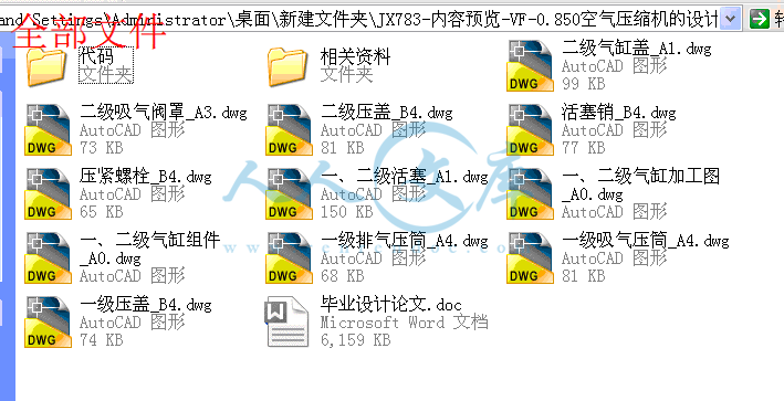
活塞销_B4.dwg---(点击预览)
毕业设计论文.doc---(点击预览)
压紧螺栓_B4.dwg---(点击预览)
二级气缸盖_A1.dwg---(点击预览)
二级吸气阀罩_A3.dwg---(点击预览)
二级压盖_B4.dwg---(点击预览)
一级排气压筒_A4.dwg---(点击预览)
一级吸气压筒_A4.dwg---(点击预览)
一级压盖_B4.dwg---(点击预览)
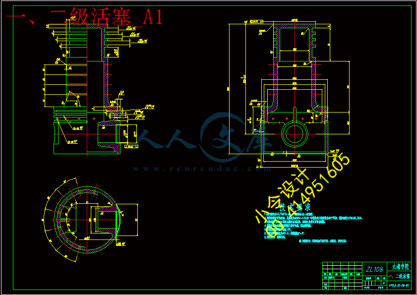
一、二级活塞_A1.dwg---(点击预览)
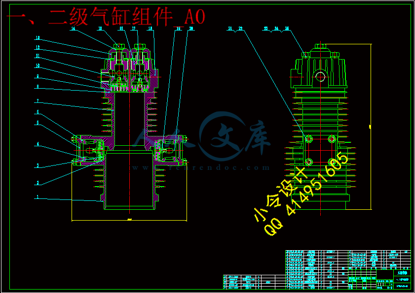
一、二级气缸组件_A0.dwg---(点击预览)
一、二级气缸加工图_A0.dwg---(点击预览)
代码
CompressorDesignServer
bin
Common
Compressor
obj
Properties
app.config
CompressorDesignServer.csproj
HandleMessage.cs
MainProgramInit.cs
Program.cs
CompressorDesignServer.sln
CompressorDesignServer.suo
X7
X7
Client
Information
MainUI
PistonCompressor
Resources
ClassDiagram1.cd
X7.csproj
X7.csproj.user
X7.sln
X7.suo
相关资料
压缩包内文档预览:
预览图 预览图 预览图 预览图 预览图 预览图 预览图 预览图 预览图
编号:436216    类型:共享资源    大小:3.45MB    格式:RAR    上传时间:2015-05-28 上传人:好资料QQ****51605 IP属地:江苏
45
积分
关 键 词:
vf 空气压缩机 设计 整体 总体 编程 二级
资源描述:

【温馨提示】 购买原稿文件请充值后自助下载。

[全部文件] 那张截图中的文件为本资料所有内容,下载后即可获得。


预览截图请勿抄袭,原稿文件完整清晰,无水印,可编辑。

有疑问可以咨询QQ:414951605或1304139763


摘  要

压缩机是用来提高气体压力和输送气体的机械。从能量转换的方式来看, 压缩机是属于将原动机的动力能转变为气体压力的工作机。本设计为中压活塞式空气压缩机设计。活塞式压缩机与其他类型的压缩机相比,其优点是:压力范围最广、效率高、适应性强,即排气量范围较广,且不受压力高低的影响。活塞式压缩机应用较广泛,例如在吹瓶机、核电站、仪表等方面,特别是在中小制冷范围内成为应用最广,生产批量最大的一种机型。

本次整个设计的内容包括压缩机的总体、气缸及基本部件的设计。主要通过热力计算和动力计算来确定压缩机的总体结构方案设计,和各种零部件的设计。同时,在本次的设计过程中,开发了一个计算机软件来完成热力计算和动力计算,借助AutoCAD绘图软件绘图。


关键词:活塞式压缩机;计算机编程;热力计算;动力计算;主要零部件设计


Abstract


The compressor is used to increase the gas pressure and gas transportation machinery. Judging from the energy conversion, the compressor is working machine, which can transform the prime mover into gas pressure. This design is for the medium-pressure piston air compressor. Compared with other types of compressors, advantages of piston compressor are: pressure range is the most extensive, high efficiency, adaptability. That means a wider range of displacement and pressure level will not affect it. The piston compressor is used widely, such as blowing machine, nuclear power plants, instrument, particularly in small and medium-sized refrigeration. It is also the largest production volume of a model.

The entire design includes the design of the compressor overall, the cylinder and the basic member. The compressor overall structure of the program and various parts of the design is mainly determined by thermodynamic calculation and dynamic calculation.In the design process, I develop a computer software to complete the thermodynamic calculation and dynamic calculation, drawing with AutoCAD drawing software.


Key words: piston compressor; computer programming; heating calculation; dynamic calculation; structural design


目  录

摘  要III

AbstractIV

目  录V

1 绪论1

1.1本课题的研究内容和意义1

1.2国内外的发展概况1

1.3本课题应达到的要求2

2总体设计方案3

2.1设计参数及依据3

2.1.1 设计参数3

2.1.2 设计活塞压缩机应符合以下基本原则3

2.2 主要结构参数的选择3

2.2.1 转速n3

2.2.2 行程S3

2.2.3 活塞平均速度4

2.3 结构方案的选择4

2.3.1 气缸排列的型式及其选择4

2.3.2 运动机构的结构及选择5

2.4 中间冷却器5

3 热力计算7

3.1 概述7

3.2 热力计算原始数据13

3.3 初步确定各级名义压力15

3.4 计算各级排气温度17

3.5 确定各级的排气系数19

3.5.1 容积系数19

3.5.2 压力系数21

3.5.3 温度系数21

3.5.4 气密系数21

3.5.5 排气系数22

3.6 确定各级干气系数22

3.7确定各级抽气系数22

3.8 确定各级气缸行程容积22

3.9 确定各级气缸直径24

3.10 圆整后各级名义压力及温度26

3.10.1 确定圆整后各级实际行程容积26

3.10.2 求各级压力修正系数、27

3.10.3 修正后各级名义压力及压力比29

3.10.4 修正后各级排气温度30

3.11 计算活塞力31

3.11.1 计算气缸内实际吸排气压力31

3.11.2 计算各列的活塞力32

3.12 计算轴功率,选取电机35

3.12.1 计算各级指示功率35

3.12.2 整个机器总指示功率36

3.12.3 轴功率36

3.12.4 选择电机36

4 动力计算37

4.1 概述37

4.2 初始数据37

4.3 作各级气缸设计示功图37

4.4 作往复惯性力图44

4.5 计算各级往复摩擦力47

4.6 作综合活塞力曲线图47

4.7 作切向力图52

4.8 确定飞轮距56

5 主要零部件设计58

5.1 一、二级气缸设计58

5.1.1 气缸结构型式58

5.1.2 气缸结构设计58

5.2 一、二级活塞组件61

5.2.1 活塞61

5.2.2 活塞环与活塞环的润滑62

5.3 一、二级气阀65

5.3.1 气阀的基本要求65

5.3.2 气阀主要参数的确定65

结论与展望71

6.1 结论71

6.2 不足之处及未来展望71

致谢72

参考文献73

附录74


1 绪论

1.1本课题的研究内容和意义

随着现代工业的发展,压缩机的使用已十分普遍,所占的地位相当重要。压缩机是输送气体介质并提高其压力能的机械装置,它在国民经济各部门中特别在化工、石油、矿山、冶金、机械、农田灌溉以及国防工业中已成为必不可少的关键设备。其重要的应用场合有:

(1)化工工艺过程上的应用

在化工生产中,为了保证某些合成工艺能在高压条件下进行,往往通过压缩机把气体

预先加压到所需的压力。例如高压聚乙烯的聚合反应要求把乙烯加压到2000kgf/cm2以上;合成氨的反应要求把合成气加到320kgf/cm2;石油裂解如氢要求把氢气加压到150kgf/cm2以上等。

(2)动力工程上的应用

在动力、机械以及国防工业上常采用压缩空气作为驱动装置的动力气源,例如常见的

风动机械,要求空气的压力为8kgf/cm2;用于控制仪表及自动化装置上的气源压力6kgf/cm2;国防工业中某些武器的发射、潜水艇的沉浮、鱼雷的发射驱动等需要采用压缩机。

(3)气体输送

在石油、化工生产中,为了输送原料气,常用压缩机增压。例如从油田输出天然气,煤气厂输出煤气都要求事先加以增压。

压缩机种类有很多,有往复式压缩机、回转式压缩机、透平式压缩机、喷射式压缩机等。其中在往复式压缩机中最典型的是活塞式压缩机。活塞式压缩机是依靠气缸内活塞的往复运动来压缩气体。活塞压缩机由于具有耗能低、适应性强和灵活性大等优点,应用比较普遍。所以活塞压缩机的设计及研究对国民经济的发展具有十分重要的意义。

由于计算机的飞速发展与普遍应用,在活塞式压缩机设计中,可以使用计算机编程来实现热力计算和动力计算。通过利用计算机编程,可以使得热力计算和动力计算变得迅捷、方便、精确。同时借助AutoCad的二次开发,可以很方便的生成气缸的示功图、综合活塞力图、切向力图和总切向力图。

本次设计中编程语言采用C#。C#是一款面向对象的编程语言,是微软公司在2000年7月推出.NET Framework的第1版时提供的一种全新语言,它从C和C++语言演化而来,并吸取了以往的教训,考虑了其他语言的许多优点,并解决了它们的问题[12]。本次设计使用Visual Studio 2010开发工具进行所有的C#编程。

1.2国内外的发展概况

近年来,国民经济不断的发展,行业集中度提高了许多,大企业进一步集中供货。气体压缩机的产业布局,正在逐步合理的向新局面发展。由于战略性的经济重组的不断推进,很多不合格的企业退出,杰出的企业找准发展方向,加强主要业务的发展,不断做大做好,达到强强联合,承担起国家重大技术装备项目。在相关政策方面,为应对全球性金融危机对我国经济的影响,早在09年年初,国家已经制定了一系列的刺激经济方案,重点调整振兴包括石化、冶金等气体压缩机的下游产业在内的十大产业。由于这些措施,使得气体压缩机产业得到了积极的发展,同时也使得压缩机行业经济在2009年的下半年逐渐变好。在开拓国际市场方面,压缩机行业应积极而谨慎地探索自己的国际化道路。近年来,压缩机行业的国际化步伐放缓,特别是在2009年,压缩机的出口形势不容乐观,这主要表现于国内压缩机行业技术发展水平与国外压缩机技术发展水平存在一定的差距,真正意义上的具有国际竞争力的大型国际企业集团还没有形成。但是在将来,压缩机的需求在我国压缩机市场中将进一步提高。

2013年,是压缩机行业发展的新起点,预计行业未来呈现出新的发展态势。首先是结构调整将有重大突破。目前在我国的压缩机行业中,企业规模小而且分散,产业集中度低;生产力布局不合理现象依然存在;企业节能减排的任务重;科技创新能力不强;资源控制力不强,保障体系建设滞后等。正因为压缩机行业中存在这些矛盾,所以,特别的要在压缩机行业中特别的调整好压缩机产业结构,不断升级产业,并且解决压缩机行业的重大问题,不影响其发展。第二,行业内要大力推动共性技术研究开发,掌握核心技术、关键技术的自主知识产权。当前,压缩机行业共性技术的科研经费投入不足,研究开发力量薄弱。2013年,各企业应加大在我国重点培育自主知识产权的技术装备研发力量。可以循序渐进地加强建设国家工程技术研究中心、国家重点实验室、行业科研院所等共性技术研究开发平台,重点对原创性技术、战略性关键技术、及共性技术的研究开发,并且培养一支既精通基础技术又熟悉行业技术的高科技人才队伍,努力使其掌握关键技术、核心技术和重要产品的自主知识产权。第三,进入加快发展制造服务业阶段。当前,压缩机行业存在一些不利于产业发展的缺陷,如缺少高端技术,企业规模偏小等。面临这些问题和激烈的市场竞争,压缩机企业极需提高自身的核心竞争力,转变增长方式。在制造过程中,并且在市场调研,销售,产品报废回收过程中,力争为客户提供方便,高品质的优异服务,这点对一个压缩机企业的发展有着重要意义,因为通过这些可以实现可持续发展。现代服务业主要投入的大部分是人力资本和知识资本,这些解决了压缩机企业发展、升级问题,并且提升了市场竞争力。

我国往复压缩机设计与制造技术水平跟国外水平相比,主要差距是在研究基础理论上的差距,开发产品的技术能力相对较低,落后国外的工艺装备和实验手段,产品技术起点不高。另外,技术含量高和特殊要求的产品在国内压缩机市场上供不应求。

1.3本课题应达到的要求

1、根据设计参数,利用计算机编程进行压缩机的热、动力计算(主要包括缸径的确定,电动机功率计算及选型,压缩机中的作用力的分析,飞轮距的确定);

2、对压缩机主要零件进行强度校核;

3、根据计算结果,确定压缩机结构尺寸,绘制主要零部件图及一、二级气缸组装图;

4、查阅相关资料,完成毕业设计说明书一份,不少于30页。


2总体设计方案

2.1设计参数及依据

2.1.1 设计参数

排气量:0.85m3/min

压缩介质:空气

进气压力:大气压

公称排气压力:5 MPa(表压力)

排气温度:25℃

2.1.2 设计活塞压缩机应符合以下基本原则

a.满足用户提出的排气量、排气压力,及有关使用条件的要求。

b. 使用寿命要足够长,即压缩机需要大修时间间隔的长,使用可靠性要足够高,及压缩机被迫停车的次数短。

c.有较高的运转经济性。

d.有良好的动力平衡性。

e.维护检修方便。

f.尽可能采用新结构、新技术、新材料。

g.制造工艺性良好。

h.机器的尺寸小、重量轻。


内容简介:
英文原文Lubricant supply system and operating method of multisystem lubrication screw compressorSekiya; Yoshimitsu (Moriya, JP)Abstract An oil refrigeration screw compressor being applied to a refrigeration system etc., in which the problem of strength reduction of a bearing material under high temperatures and that of lifetime reduction of the bearing material due to viscosity lowering of lubricant are solved. A lubricant supply system to a compressor body is divided into a bearing oil supply system for supplying lubricant to each bearing of the compressor body at low pressure and into a temperature control oil supply system for supplying lubricant into the compressor body at high pressure. The bearing oil supply system is a closed circuit oil supply system comprising an oil supply tank, an oil cooler, and an oil supply pump, and the temperature control oil supply system is a closed circuit oil supply system comprising an oil separator and an oil cooler. BEST MODE FOR EMBODIMENT OF THE INVENTION Preferred embodiment of the present invention will now be detailed with reference to the accompanying drawings. It is intended, however, that unless particularly specified, dimensions, materials, relative positions and so forth of the constituent parts in the embodiments shall be interpreted as illustrative only not as limitative of the scope of the present invention. FIG. 1 is a schematic illustration of an example of lube oil supply line of the screw compressor according to the present invention in a perspective view. In FIG. 1, reference numeral I is an oil supply line for controlling temperature, lube oil is supplied through this line to be injected from a slide valve toward screw rotors b consisting of a male rotor and a female rotor in order to control temperature of the compressed fluid discharged from the compressor together with the compressed fluid. Reference numeral II is a bearing lubricating oil supply line, lube oil is supplied through this line to sleeve bearings d and thrust bearings e of rotor shafts c, to a balance piston g for reducing thrust load, and to an oil seal h, and flows out to a return path II which communicates to an oil supply tank not shown in the drawing. Reference numeral III is an oil supply line for supplying oil to a hydraulic piston p for driving the slide valve a. This line is a closed line provided separately from the line I and II which are related to the present invention, The line III is not related to the invention, so explanation is omitted. By providing the oil supply lines I and II separately from each other in the invention, the compressor can be operated at optimal conditions concerning temperature, pressure, and flow rate of lube oil supplied via each of the oil supply lines, and the objects of the present invention can be attained. Next, in FIG. 2 showing the lube oil supply system of the first embodiment of the invention, reference numeral 1 is a screw compressor, 2 is a screw rotor of a pair of male and female screw rotors supported rotatably in the rotor casing of the compressor 1, 3 is a slide valve for injecting lube oil to the rotor 2 in the rotor casing. Reference numeral 1a is a suction port of fluid f to be compressed, 1b is a discharge port of compressed fluid f, and 2a is a shaft part of the rotor 2. The fluid f to be compressed is sucked from the suction port 1a into the compressor 1 and compressed as the rotors 2 rotate to be discharged in a pressurized state together with lube oil mixed in it. The mixed lube oil is separated from the compressed gas in an oil separator 4. The separated lube oil is cooled in an oil cooler 5, filtered through a filter 6 to remove foreign matter, and again returned to the slide valve 3. This closed circulation circuit composes the temperature control, oil supply line I and shown by a broken line. Reference numeral 7 is an oil supply tank in which lube oil is reserved, the oil reserved in the oil supply tank 7 is supplied by means of an oil supply pump 8 to rotor bearing parts of the compressor via an oil cooler and a filter 10. The lube oil supplied to the rotor bearing parts is recovered to the oil supply tank 7 passing through a return path L.sub.3. This closed circuit composes the bearing lubricating oil supply line II and shown by a solid line. The oil supply tank 7 is provided with a liquid-level meter 13 for detecting oil levels and a liquid level transmitter 11 for sending oil levels detected by the liquid-level meter 13 to an oil-level control operator 12. A temperature control valve 14 is provided in the upstream of the oil cooler 9, a branch path L.sub.1 branches from the temperature control valve 14, and a branch path L.sub.2 equipped with a pressure regulator valve 15 branches from the branch path L.sub.1 for allowing a part of the lube oil from the oil supply pump 8 to be returned to the oil supply tank 7. A path L.sub.4 is provided which communicates the gas zone in the upper part of the oil supply tank 7 to a position near the suction port 1a, a pressure regulator valve 16 is provided in the path L.sub.4, and a path L.sub.5 having a flow regulator valve 17 is provided for allowing the lube oil in the oil supply line II to be supplied to the position near the suction port 1a. A path L.sub.6 is provided to the temperature control oil supply line I for supplying a part of the lube oil to in the line to the oil supply tank 7, and a filter 18 and a flow regulator valve 19 are provided in the path L.sub.6. A temperature control valve 20 is provided in the downstream of the oil cooler 5, and a path L.sub.7 branches from the temperature control valve 20. The oil separator 4 is provided with a liquid-level meter 22 for detecting oil levels and a liquid-level switch 21 for allowing an alarm to be sounded when the detected oil level has lowered to a limit level. Reference numerals 23, 24, and 25 are temperature detectors for detecting and transmitting signals of detected temperatures, and reference numeral 26, 27, 28, and 29 are pressure detectors for detecting pressure and transmitting signals of detected pressures provided to each of the paths respectively. Reference numeral 30 is a flow detector, 31 is a control operator for determining oil pressure adequate or optimal for the bearing lubricating oil supply line II based on the pressure difference between the upstream and downstream zone of the oil supply pump 8 and on the pressure difference between the temperature control oil supply line I and bearing lubricating oil supply line II, and for controlling the pressure regulator valve 15 so that said adequate oil pressure is realized in the bearing lubricating oil supply line II. Reference numerals 32, 33, 34, and 35 are non-return valves, and 36 is a manual valve. FIG. 3A shows arrangement of rotors and bearing parts of the first embodiment shown in FIG. 1. In the drawing, lube oil injected into the rotor room to control temperature of compressed fluid f is indicated by I, and lube oil supplied to lubricate bearings is indicated by II. In FIG. 3A, reference numeral 2 is a pair of male and female rotors, each of the rotors 2 is supported by journal bearings 42 at its shaft parts 2a extending from both ends thereof. Reference numerals 41 are oil seals, 43 are thrust bearings. Reference numeral 44 is a mechanical oil seal. FIG. 3B and FIG. 3C are respectively an enlarged sectional view of the journal bearing indicated by an arrow B and arrow C in FIG. 3A. In FIG. 3B and FIG. 3C, an oil groove 45, 46 is provided in each of the journal bearings for returning lube oil to the oil supply tank 7 via the oil return path L.sub.3. Journal bearings of this type may be used together with the oil seals 41 or without the oil seals 41. In the first embodiment shown in FIG. 2 and FIG. 3A, lube oil supplied via the temperature control oil supply line I and via the bearing lubricating oil supply line II inevitably mix with each other, so preferably lube oil of the same kind is used for the lines I and II. Lube oil for controlling temperature can be injected into the rotor room by utilizing pressure difference between the discharge pressure at the discharge port 1b and the pressure in the rotor space under compression process. As to temperature of oil, temperature of the oil supplied via the temperature control oil supply line I and that supplied via the bearing lubricating oil supply line II can be made different, for the two lines I and II are separate lines. It is effective, for example, to raise the temperature of the oil injected into the rotor room for temperature control in order to prevent occurrence of condensation of the gas compressed in the compressor by decreasing or stopping oil flow and decrease the temperature of the oil supplied to the bearings in order to secure proper viscosity of the lube oil. Herewith, aforementioned problems in the prior art, that is, reduction in strength of slide bearings due to heat generation by friction and reduction in bearing life due to lowering in viscosity of lube oil, can be prevented. According to the embodiment, injection oil supplied to the rotor room can be raised in temperature or decreased in flow rate for the purpose of preventing occurrence of condensation of compressed fluid, so the amount of lube oil mixed in the fluid can be reduced. Therefore, the oil separator in the temperature control oil supply line I can be small sized and oil separation efficiency can be increased. Further, intrusion of foreign matter contained in the fluid f to be compressed to the bearing lubricating oil supply line II can be suppressed to the minimum. On the other hand, the amount (flow rate) of lube oil for lubricating rotor bearings can be reduced to the minimum and its temperature can be lowered below permissible temperature for bearing lubrication. Therefore, it is made possible to adopt low viscosity lube oil, for example, mineral oil, and also to maintain the compressed gas in high temperature without excessively cooled by lube oil. Further, by providing the path L.sub.3 in the bearing lubricating oil supply line II in order to recover the lube oil after lubricating bearings of the compressor 1 to the oil supply tank 7 and the path L.sub.6 in the temperature control oil supply line I in order to supply a part of the lube oil separated in the oil separator 4 and cooled by the oil cooler 5, lube oil in both lines including lube oil leaked between both lines can be eventually recovered to the oil supply tank 7 in the bearing lubricating oil supply line II, so a little leakage between both lines is acceptable. The same lube oil must be used for both lines, for lube oil in both lines mixes with each other.As shown in FIG. 3, by adopting slide bearings for supporting rotatably the rotors 2 and providing grooves 45 and 46 respectively near the rotor end face side end of each slide bearing to allow lube oil to be accumulated therein so that the lube oil accumulated in the groove is introduced to the lube oil recovery path L.sub.3 of low pressure, supply and recovery of lube oil for lubricating the bearings can be performed easily and positively, and leakage of lube oil from bearing space into the rotor casing or on the contrary from the rotor casing into the bearing space can be suppressed to the minimum while allowing the leakage of a certain amount of lube oil. That is, leakage of lube oil can be suppressed by allowing lube oil to accumulate transiently in the grooves and recovering again to another low pressure lube oil recovering path. By this, lube oil leakage between both lines I and II can be minimized. Further, by providing the path L.sub.4 for communicating the gas zone in the oil supply tank 7 in the bearing lubricating oil supply line II to a position near the suction port 1a and attaching the pressure regulator valve 16 to the path L.sub.4, pressure of the gas zone in the oil supply tank 7 in the bearing lubricating oil supply line II can be made to be at a pressure the same as suction pressure of fluid f to be compressed or intermediate pressure between suction and discharge pressure, so pressure rise in the oil supply tank 7 in the bearing lubricating oil supply line II when starting operation of the compressor 1 can be prevented, and it is made possible that oil injection into the rotor room can be performed by pressure difference between discharge pressure detected by the pressure detector (26) and suction pressure detected by the pressure detector (28), that is, oil supply by pressure difference in operation can be adopted. Further, by providing the branch path L.sub.2 for returning lube oil in the downstream of the oil supply pump 8 to the oil supply tank 7, attaching the pressure regulator valve 15 to the branch path L.sub.2, and providing the control operator 31 for controlling the opening of the pressure regulator valve 15 based on the pressure difference between oil pressure in the downstream and upstream of the oil supply pump 8 (pressure difference between the pressure detected by the pressure detector 27 and that detected by the pressure detector 28) and the pressure difference between discharge gas pressure in the temperature control oil supply line I (pressure detected by the pressure detector 26) and oil pressure in the downstream of the oil supply pump 8 (pressure detected by the pressure detector 27), a rapid pressure rise in the lube oil recovery path L.sub.2 when staring operation of the compressor can be alleviated. Further, by providing the oil-level meter 11 to the oil supply tank 7 in the bearing lubricating oil supply line II, providing the path L.sub.5 for returning lube oil from the oil supply tank 7 to the temperature control oil supply line I, providing the flow regulator valve 17 to the path L.sub.5, providing the flow regulator valve 19 to the path L.sub.6 in the temperature control oil supply line I to recover a part of lube oil to the oil supply tank 7, the flow regulator valves 17 and 19 being controlled based on the oil level detected by the oil-level meter 11, and providing the control operator 12 for controlling the level of the oil in the oil supply tank 7 in a predetermined range, the level of the oil in the oil supply tank 7 can be maintained in a prescribed range and variation of the oil level caused by oil leak between the bearing lubricating oil supply line II and temperature control oil supply line I etc. can be suppressed. Further, by providing the branch path L.sub.1 for allowing the lube oil discharged from the oil pump 8 to bypass the oil cooler 9 in the bearing lubricating oil supply line II, attaching the temperature control valve 14 for controlling lube oil temperature to the branch path L.sub.1, and controlling temperature of lube oil supplied to the bearings of the rotors by controlling the opening of the temperature control valve 14, lube oil of low temperature and high viscosity can be supplied to the bearings of the rotors. Further, by adopting an operating method with which the gas zone in the upper part of the oil supply tank 7 is maintained at the same pressure as suction pressure of the compressor 1 or intermediate pressure between suction and discharge pressure, pressure difference is produced between the discharge pressure of the compressor and the oil supply pressure of the bearing lubricating oil supply line II, and it is made possible to adopt oil supply by pressure difference in operation to inject oil into the rotor room toward the rotors by pressure difference between the discharge and suction pressure of the compressor, and by maintaining the gas pressure in the oil supply tank 7 to be the same as suction pressure or intermediate pressure between suction and discharge pressure, abnormal rise in pressure in the bearing lubricating oil supply line II can be prevented. Although the valves 16, 17, and 19 are closed so that the lube oil in the temperature control oil supply line I does not mix with the lube oil in the bearing lubricating oil supply line II when operation of the system is halted, occurrence of oil leak from the rotor room to bearings can no be evaded, and it is thought that the pressure in the oil supply tank 7 becomes the same as pressure of process gas, i.e. discharge pressure of the fluid f. By controlling pressure difference between the pressure in the temperature control oil supply line I and that in the bearing lubricating oil supply line II, a rapid rise in oil pressure in the bearing lubricating oil supply line II can be prevented when the oil supply pump 8 is driven by starting operation of the system next time. Further, the pressure regulator valve 16 is controlled so that pressure in the oil supply tank 7 gradually becomes a prescribed pressure in idle operation with a minimum load after starting of operation of the system. In the embodiment, a balance piston is provided to avoid excessive thrust force from exerting on the thrust bearing, and when starting, the slide valve 3 is positioned at a low load position for reducing starting torque, so occurrence of excessive thrust force can be avoided even when pressure of oil supplied to the balance piston is low. Therefore, it is also possible to determine bearing lubricating oil pressure which is detected by the pressure detector 27 so that the flow rate of the oil is at a minimum necessary flow rate. When oil pressure required to be supplied to the balance piston in ordinary operation, it will be effective to provide an oil supply line for supplying oil to the balance piston separately from the other bearing lubricating oil supply line. In such a case, the flow rate in the other bearing lubricating oil supply line is controlled for securing a minimum necessary flow of lube oil. When starting operation, it is supposed that there exists no lube oil in the rotor room. As oil injection into the rotor room by pressure difference between discharge pressure and suction pressure of the compressor, a state of no lubrication occurs in the rotor room although for a short period at the start of operation of the compressor. Therefore, heat generation is feared to occur by the contact of the male rotor with female rotor unless the compressor is of a type in which engagement of the rotors is defined by timing gears, so it is suitable to open the flow regulator valve 17 a little when starting. In order to minimize leakage of high-pressure gas and oil from the rotor room to the bearing lubricating oil supply line II just after halting operation of the compressor, it is also effective to provide a non-return valve or automatic valve between the screw compressor and the oil separator 4 so that high pressure gas does not intrude into the inside of the compressor as far as possible. All of the oil supply lines are basically closed circuits although oil leak may occur between each of the lines, oil levels in the oil supply tank 7 and oil separator 4 can be controlled by controlling the flow regulator valves 17 and 19 by the oil-level control operator 12. However, in an open cycle of compressing gas by a screw compressor, the oil in the injection oil supply line reduces in amount by little and little and will eventually be exhausted, for a part of the oil is sent out of the line together with the compressed gas. When the oil in the injection supply line is exhausted, there is no choice but to supply oil from the bearing lubricating oil supply line II by opening the flow regulator valve 19. When operating continuously, some amount of oil leaking from the bearings into the rotor room can be expected to serve as injected oil, and it is thought that operation may be able to be continued even if oil is deleted in the temperature control oil supply line I. However, as to the bearing lubricating oil supply line II, deletion of oil is not permissible. Therefore, as to control by the control operator 31, it is effective in ordinary continuous operation that the control of the level of oil in the oil supply tank 7 is performed preferentially by the control operator 12. There is a way to provide a lower limit alarm as to the amount of oil in the injection oil supply line I , but since the injection oil supply exercises an effect only on discharge gas temperature of the compressor, operation of the compressor is stopped by the trip of excessive high temperature when the discharge gas temperature is higher than a prescribed temperature. FIG. 4 is a partial block diagram of the second embodiment of lube oil supply system of screw compressor according to the present invention. In FIG. 4, the same instruments and parts as sown in FIG. 2 and FIG. 3 are indicated by the same reference numerals. In FIG. 4, a path L.sub.8 is an oil supply path branching from the bearing lubricating oil supply line II in order to supply oil to a balance piston 51, reference numeral 52 and 53 are respectively a flow regulator valve and a flow detector for detecting flow rates and transmitting signals of detected flow rates provided to the bearing lubricating oil supply line II. Construction except those instruments and parts that are added is the same as that of the first embodiment. In the second embodiment, oil to be supplied to the balance piston 51 and oil to be supplied to bearings and oil seals are pressurized by the oil supply pump 8, and the pressurized oil supply is divided in two lines so that high-pressure oil is supplied to the balance piston which require high-pressure oil supply and oil reduced in pressure is supplied to bearings/oil seals to which the amount of oil supply is important rather than pressure. Pressure control after pumping up by the oil supply pump 8, that is, pressure control of oil supply to the balance piston 51 is performed by the control operator 31 which calculates first the thrust force exerting on the male rotor based on the discharge gas pressure detected by the pressure detector 26 and suction gas pressure detected by the pressure detector 29, then determines requisite counter force to be applied to the balance piston 51, and controls the pressure of the oil supplied to the balance piston by controlling the pressure control valve 15 so that the requisite counter force is applied to the balance piston by the pressure of the oil supplied to the balance piston. The flow of oil supplied to the bearings/oil seals is controlled by adjusting the flow regulator valve 52 so that the flow rate detected by the flow detector 53 is always necessary flow rate. When the compressor is operated at a light load, lower bearing lubricating oil pressure is acceptable but minimum requisite oil flow rate must be secured. According to the second invention, by dividing the bearing lubricating oil supply line II into two lines, i.e. the oil supply line L.sub.8 to supply oil to the balance piston 51 and the other line to supply oil to bearings/oil seals, and providing the flow regulator valve 52 to said other line to supply oil to bearings/oil seals, proper oil pressure and proper oil flow rate can always be maintained respectively for the balance piston and be
温馨提示:
1: 本站所有资源如无特殊说明,都需要本地电脑安装OFFICE2007和PDF阅读器。图纸软件为CAD,CAXA,PROE,UG,SolidWorks等.压缩文件请下载最新的WinRAR软件解压。
2: 本站的文档不包含任何第三方提供的附件图纸等,如果需要附件,请联系上传者。文件的所有权益归上传用户所有。
3.本站RAR压缩包中若带图纸,网页内容里面会有图纸预览,若没有图纸预览就没有图纸。
4. 未经权益所有人同意不得将文件中的内容挪作商业或盈利用途。
5. 人人文库网仅提供信息存储空间,仅对用户上传内容的表现方式做保护处理,对用户上传分享的文档内容本身不做任何修改或编辑,并不能对任何下载内容负责。
6. 下载文件中如有侵权或不适当内容,请与我们联系,我们立即纠正。
7. 本站不保证下载资源的准确性、安全性和完整性, 同时也不承担用户因使用这些下载资源对自己和他人造成任何形式的伤害或损失。
提示  人人文库网所有资源均是用户自行上传分享,仅供网友学习交流,未经上传用户书面授权,请勿作他用。
关于本文
本文标题:VF-0.850空气压缩机的设计(整体设计编程,一、二级缸设计)【11张CAD图纸+毕业论文】【答辩通过】
链接地址:https://www.renrendoc.com/p-436216.html

官方联系方式

2:不支持迅雷下载,请使用浏览器下载   
3:不支持QQ浏览器下载,请用其他浏览器   
4:下载后的文档和图纸-无水印   
5:文档经过压缩,下载后原文更清晰   
关于我们 - 网站声明 - 网站地图 - 资源地图 - 友情链接 - 网站客服 - 联系我们

网站客服QQ:2881952447     

copyright@ 2020-2025  renrendoc.com 人人文库版权所有   联系电话:400-852-1180

备案号:蜀ICP备2022000484号-2       经营许可证: 川B2-20220663       公网安备川公网安备: 51019002004831号

本站为文档C2C交易模式,即用户上传的文档直接被用户下载,本站只是中间服务平台,本站所有文档下载所得的收益归上传人(含作者)所有。人人文库网仅提供信息存储空间,仅对用户上传内容的表现方式做保护处理,对上载内容本身不做任何修改或编辑。若文档所含内容侵犯了您的版权或隐私,请立即通知人人文库网,我们立即给予删除!