设计说明书-22694字-66页.doc

超声旋风铣削设计【12张CAD图纸+毕业论文】【答辩通过】

收藏

资源目录
跳过导航链接。
压缩包内文档预览:(预览前20页/共68页)
预览图 预览图 预览图 预览图 预览图 预览图 预览图 预览图 预览图 预览图 预览图 预览图 预览图 预览图 预览图 预览图 预览图 预览图 预览图 预览图
编号:436454    类型:共享资源    大小:4.45MB    格式:RAR    上传时间:2015-05-28 上传人:好资料QQ****51605 IP属地:江苏
45
积分
关 键 词:
超声 旋风 铣削 设计
资源描述:

【温馨提示】 购买原稿文件请充值后自助下载。

[全部文件] 那张截图中的文件为本资料所有内容,下载后即可获得。


预览截图请勿抄袭,原稿文件完整清晰,无水印,可编辑。

有疑问可以咨询QQ:414951605或1304139763


摘 要

旋转超声加工是集传统超声加工与磨粒磨削加工为一体的复合加工,是加工硬脆性材料的一种有效方法,具有良好的应用前景。然而,通过大量文献的阅读及实际的调查研究发现,国内目前还没有生产完善的旋转超声加工机床,超声加工的技术也远远滞后于发达国家的水平。

现今超声加工的工艺效果十分显着,国内外不断将超声加工与普通加工方式相结合应用,取得了较好的效果。超声加工具有较好的表面质量,不会产生表面烧伤和表面变质层。我们提出将超声加工与旋风铣削相结合来加工螺纹,在普通旋风铣削的装置的基础上进行结构的改进并加以超声装置,形成一套新的复合式的工艺装备,并仍与普通机床配套使用,不失其安装使用的灵活性。可以看出,改进后的超声旋风铣削装置可以弥补普通冷切削加工的不足,尤其适宜硬脆等难加工材料的加工,显著提高螺纹的加工质量。


关键字:旋风铣  超声  螺纹  变幅杆


Abstract

Rotary ultrasonic machining is a hybrid machining process which combines thematerial removal mechanisms of conventional ultrasonic machining (CUSM) and diamondgrinding. It is not limited by the electrical or chemical characteristics of the workpiecematerials. Thus it has been proved to be a promising and cost-effective machining methodfor hard and brittle materials, such as engineering ceramic, glass, stone, which has beenwidely used in many fields such as electronics, metallurgy, chemistry industry, machine,energy power, aviation and space flight.

Effect of ultrasonic machining process is very significant, domestic and abroad constantly ultrasonic machining processing methods combined with general application and achieved good results. Ultrasonic machining has good surface quality, does not produce surface burns and surface modification layer. We propose to ultrasound processing and integration to process Whirling threads, in general whirlwind milling devices based on the structure of improvement, and ultrasonic devices to form a new compound technology and equipment, and is still supporting the use of ordinary tools ,flexibility of installation and use is also very good. So that, the improved ultrasound equipment can make up ordinary Whirling cold cutting low, particularly suitable for processing hard and brittle materials such as hard processing, significantly improving the quality of thread processing.


Keyword:Whirlwind milling   Ultrasound   Screw thread

ultrasonic horn


前 言1

1 绪论3

1.1本课题来源及研究意义3

1.2 课题目前研究现状4

2 超声加工及旋风铣的基本介绍7

2.1超声波及其特性7

2.2超声加工基本原理9

2.3 旋风铣加工的基本介绍12

2.3.2旋风铣削加工螺纹的特点14

2.3.3 旋风铣削装置介绍15

2.4 典型螺纹类工件的加工情况17

3 超声旋风铣加工工艺22

3.1 普通蜗杆方法加工的工艺22

3.1.1 零件工艺性分析22

3.1.2 毛坯选择23

3.1.3 设计毛坯图25

3.1.4机械工艺路线确定26

3.1.5 定位基准的选择28

3.1.6 设备及其工艺装备确定28

3.1.7 车切削用量、工时定额确定29

3.2按旋风铣削加工方法进行的蜗杆加工32

4 超声加工装置设计34

4.1 超声加工装置的主要组成34

4.1.1 超声波发生器34

4.1.2 超声换能器36

4.2 超声振动系统设计38

4.3 超声变幅杆的设计39

4.3.1 超声变幅杆39

4.3.2变幅杆材料的选择42

4.3.3 变幅杆参数的设计43

4 4 1 变幅杆与换能器的连接与固定52

4.4 2 变幅杆的固定53

5 装置的设计与选用55

5.1 电动机的选择55

5.2 V带传动设计56

5.3 花键轴的设计58

5.5 各装置设计60

5.5.1刀体和刀头设计60

5.5.2 超声加工主轴设计61

5.5.3 旋风铣装置整体设计62

5.5.4安装于机床后示意图63

致谢64

参考文献65

前 言

毕业设计是学生学完大学教学计划所规定的全部基础课和专业课后,综合运用所学的知识,与实践相结合的重要实践性教学环节。它是大学生活最后一个里程碑,是四年大学学习的一个总结,是我们结束学生时代,踏入社会,走上工作岗位的必由之路,是对我们工作能力的一次综合性检验。

1)毕业设计的目的

通过本次毕业设计,使达到以下几个效果:

(1)巩固、扩大、深化学生以前所学的基础和专业知识;

(2)培养学生综合分析、理论联系实际的能力;

(3)培养学生调查研究、正确熟练运用国家标准、规范、手册等工具书的能力;

(4)锻炼进行设计计算、数据处理、编写技术文件、绘图等独立工作能力。

总之,通过毕业设计使学生建立正确的设计思想,初步掌握解决本专业工程技术问题的方法和手段,从而使学生受到一次工程师的基本训练。

2)毕业设计的主要内容和要求

本次毕业设计的主要内容是超声旋风铣削的设计。具体设计内容和要求如下:

(1)调查螺纹蜗杆类零件对旋风铣削机床的具体要求,现在使用的加工方法;收集并分析国内外同类型加工方法的先进技术、发展趋势以及有关的科技动向;调查制造厂的设备、技术能力和生产经验等。

(2)设计装置的总体结构选择、传动参数设计、超声加工部件的选定与典型工件工艺的初步制定,确定各部分的相互关系;拟订总体设计方案,根据总体设计方案,选择通用部件,并绘制各零件的零件图和装配图;

   (3)进行电机及各传动系统的运动计算和动力计算;

(4)超声加工部分零部件的设计和选择;

(5)编制设计技术说明书一份。

3)程序和时间安排

毕业设计是实践性的教学环节,由于时间的限制,本次毕业设计不可能按工厂的设计程序来进行,具体的说,可以分以下几个阶段:

(1)实习阶段,通过毕业实习实地调查、研究、收集有关资料,掌握超声加工加工技术,了解机床的结构、工作原理和设计的基本要求,花两周时间;

(2)制定方案、总体设计阶段,花两周时间;

(3)计算和技术设计阶段,绘制图纸,整理设计说明书,花四周时间;

(4)答辩阶段,自述设计内容,回答问题,花半周时间。


1 绪论

1.1本课题来源及研究意义

目前旋风铣螺纹存在的加工质量不高,以及其在硬脆材料加工上的不足,我们提出将超声加工与其复合,以在加工方式的根本问题上解决以上问题。目前国内外在此方面的研究尚属空白,具有一定的独创性和设计的合理性。在已有的旋风铣技术和超声加工技术的基础上,我们进行了超声旋风铣削的装置及工艺方面的设计。

现今超声加工的工艺效果十分显着,国内外不断将超声加工与普通加工方式相结合应用,超声加工具有较好的表面质量,不会产生表面烧伤和表面变质层。在旋风铣的基础上,我们提出将超声加工与旋风铣削相结合来加工螺纹,在普通旋风铣削的装置的基础上进行结构的改进并加以超声装置,形成一套新的复合式的工艺装备,并仍与普通机床配套使用,不失其安装使用的灵活性。可以看出,改进后的超声旋风铣削装置可以弥补普通冷切削加工的不足,尤其适宜硬脆等难加工材料的加工,显著提高螺纹的加工质量。

从已发表的文献资料来看,目前国内外学者对于旋转超声设备及其加工的研究存在很多的不足。

1)在旋转超声加工的设备方面,仅有个别实力雄厚的科研单位购买、使用价格昂贵的进口机床。国内没有专业从事旋转超声加工设备制造的商家,因此市场上没有出现完善机型。文献中所提到的设备,基本上都是在自身认识的基础上搭建简单的实验平台,将普通超声装置和钻铣床通过简单装配而成,或是探索性设计小功率超声加工机,因而出现设备个体差异大、超声功率低、超声能耗大、系统发热严重、加工性能差、超声波电源功率元件寿命低、旋转转速低等一系列问题。

2)在旋转超声加工实验研究方面,受限于超声加工设备的上述局限,目前基本上都集中在陶瓷等硬脆性材料的小孔加工方面,很少有关大平面磨抛加工的报到。为了拓宽硬脆性材料的应用,亟待解决此类材料的高效平面加工的技术“瓶颈”。

3)这些关于旋转超声孔加工实验研究多是集中在加工参数对材料去除率的影响、旋转超声加工机理及材料去除机理上。而在金刚石工具基体材料的选择、优化设计、金刚石工具的制作工艺对加工性能的影响、工具的寿命、加工过程中力的监控和控制等方面涉及较少,还没有形成统一的认识。这些问题的解决,将会更好解释旋转超声加工在硬脆性材料加工方面所具有的优越性,从而在推动旋转超声加工的研究及应用,解决目前非金属高性能材料在加工与使用的矛盾,促进其在工业应用上的发展。

1.2 课题目前研究现状

超声波加工技术的研究可追溯到1927年R.w.Wood和AIfred L LoomiS的奠基性工作,并于1954年由L.Balamuth研制出第一台超声波加工机床。半个多世纪以来,经过各国学者的不懈努力,这一技术已有了长足的进步。主要体现在如下几个方面:

1)实验出加工参数(振幅、频率、静压力、磨料材料及颗度、悬浮工作液的浓度和工作液循环方式等)对加工效率的影响规律;

2)总结出静压力、工件材料硬度加工具材料硬度是影响工具损耗的主要因素;

3)总结出磨料粒度及悬浮工作液的均匀性对工件表面质量具有影响规律;

4)利用有限元的方法,使变幅杆的设计更合理;

5)机械增益Q值高的材料用于制作变幅杆,性能优良的PCD用于制做工具头,使加工效率大大提高;

6)工具头回转的超声波加工使加工效率提高3至4倍;

7)采用性能优良的压电陶瓷换能器使加工机床的体积大大减小,能量利用率大大提高。

90年代Suzuki,K.研制的工程陶瓷无旋转超声波磨削新技术明显提高家工效率,也可以用来成型加工较复杂的型面。

1996年,德国亚琛工大研制了一种新的超声研磨技术,用它不仅可以进行超声仿形,而且可以根据工具的轨迹运动产生各种不同的曲面。

Z.J.Pei研制出旋转超声波面铣削加工新技术,并进行了实验研究。利用工具共振频率和工具长度的关系,通过检测超声波加工过程中工具的共振频率来监测工具的损耗。

随着超声波加工技术的研究进展和新技术的不断出现,超声波加工的应用范围在不断扩大。产生于60年代,在近40年中逐步发展起来的超声波旋转加工方法把金刚石工具的优良切削性能与工具的超声频振动结合在一起,可很好地提高加工效率,减小工具磨损,同样条件下,旋转超声加工RUM加工速度是传统USM的10倍,是传统磨削的6~10倍。

由于超声旋转加工只能加工圆形孔和型腔,z.j.Pei将其拓展到超声波面铣削方法加工陶瓷,并通过实验研究了陶瓷材料塑性去除及脆性去除机理。配以适当的数控系统,借鉴数控铣削的方法,国外许多学者正在开展数控超声旋转加工技术的研究。最近,德国已有成型的DMS系列超声加工机床上市,有3轴联动控制和5轴联动控制两种类型,主轴转速20~6000r/min,还可选配刀库和自动换刀装置,从而成为既具有超声波加工功能,又能进行钴、铣、磨等多工序复合加工的机床。近几年,国内清华大学、太原理工大学和大连理工大学对旋转超声波加工技术进行了初步研究。

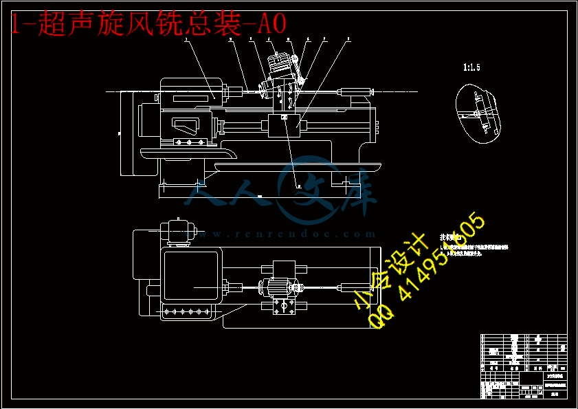
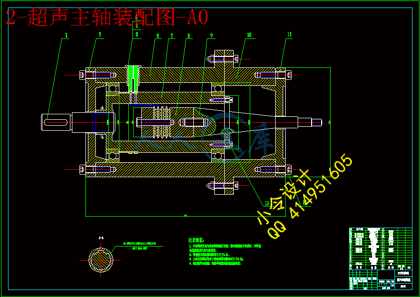
内容简介:
journal of materials processing technology 1 9 7 ( 2 0 0 8 ) 200205journal homepage: /locate/jmatprotecComparison of slurry effect on machiningcharacteristics of titanium in ultrasonic drillingR. Singha, J.S. KhambabaMechanical & Production Engineering Department, G.N.D.E. College, Ludhiana 141006, IndiabMechanical Engineering Department, Punjabi University, Patiala 147004, Indiaa r t i c l ei n f oArticle history:Received 24 December 2006Received in revised form28 May 2007Accepted 1 June 2007Keywords:Ultrasonic drillingMaterial removal rateTool wear rateSilicon carbideBoron carbideAluminaStainless steelTitaniumHigh speed steela b s t r a c tThis paper initially reviews machining of titanium and its alloys with three different slur-ries (namely silicon carbide, boron carbide and alumina) and details background work onmachinability of the same in ultrasonic drilling. Experimental research has been subse-quently presented on the production of 5mm diameter holes in pure titanium (TITAN15,ASTM Gr2) and titanium alloy (TITAN31, ASTM Gr.5) using ultrasonic drilling. This entailedthe use of a 20kHz piezoelectric transducer with three solid tools of stainless steel, titaniumand high-speed steel, operating in silicon carbide, boron carbide and alumina slurry. Thedata presented includes main effect plots for material removal rate and tool wear rate. Theresults suggested that boron carbide slurry and stainless steel tool was giving best materialremoval rate. Also relative hardness of toolwork piece affects the material removal rate inultrasonic machining. 2007 Elsevier B.V. All rights reserved.1.IntroductionTitanium alloys are generally regarded as been amongst themost difficult of work piece materials to machine in spite oftheir relatively low hardness (e.g. Ti 6/4 annealed 350HV).This is due to their low thermal conductivity, which con-centrates heat in the cutting zone (Ti 6/4 has a thermalconductivity of 11W/mK for AISI 405 steel), high chemicalreactivity at elevated temperature and a tendency to formlocalized shear bands. Titanium and its alloys are branded asdifficult to machine materials (Verma et al., 2003). Unfortu-nately, the machining of titanium is in general more difficultand consequently a significant proportion of production costsCorresponding author.E-mail address: rupindersingh78 (R. Singh).may relate to machining, even though only small volumes ofmaterial may be removed. Titanium and its alloys are verypopular and are very widely used in aerospace, marine gasturbine engines and surgical applications. Poor thermal con-ductivity of titanium alloys retard the dissipation of heatgenerated, creating, instead a very high temperature at thetoolwork piece interface and adversely affecting the toollife (Dornfeld et al., 1999). Titanium is chemically reactive atelevated temperature and therefore the tool material eitherrapidly dissolves or chemically reacts during the machin-ing process resulting in chipping and premature tool failure(Verma et al., 2003). Compounding of these characteristics isthe low elastic modulus of titanium, which permits greater0924-0136/$ see front matter 2007 Elsevier B.V. All rights reserved.doi:10.1016/j.jmatprotec.2007.06.026journal of materials processing technology 1 9 7 ( 2 0 0 8 ) 200205201deflection of the work piece and once again adds to thecomplexityofmachiningthesealloys(SME,1985).Theconven-tional machining processes thus are unable to provide goodmachining characteristics on titanium alloys. Commerciallythese alloys are machined by electric discharge machining,which is giving good material removal rate however accuracyand surface finish are some problematic area. Another non-conventional machining process that is ultrasonic drilling iswidely used nowadays for both conductive and non-metallicmaterials; preferably those with low ductility (Koval Chenkoet al., 1986; Kremer et al., 1988; Moreland, 1988) and hard-ness above 40HRC (Verma et al., 2003; Dornfeld et al., 1999;Ezugwa and Wang, 1997; Gilmore, 1990), e.g. inorganic glasses,silicon nitride, etc. (Thoe et al., 1998; IMS, 2002; Khamba andSingh Rupinder, 2003; Benedict Gary, 1987; Haslehurst, 1981;Pentland and Ektermanis, 1965). In this process tool is madeof tough material, oscillated at frequencies of the order of2030Kc/s with amplitude of about 0.02mm. An abrasive filledfluid flushed through the gap between master and work piece.The material removal mechanism involves both erosion andgrinding (Benedict Gary, 1987). The principle of stationaryultrasonic drilling has been shown in Fig. 1.The tiny abrasivechip off microscopic flakes and grinds a counterpart of face.The work material is not stressed, distorted or heated becausethegrindingforceisseldomover2lb(IMS,2002).Thereisneverany tool to work contact, and presence of cool slurry makesthis a cold cutting-process.The tool used for machining has been prepared by sil-ver brazing process (Singh, 2002). The amplitude of vibrationsgiven to the tool also influences the cutting rate (Khamba andSingh Rupinder, 2003). It has been found that the materialremoval rate is affected by amplitude of oscillations, size ofabrasive (Singh, 2002; Singh and Khamba, 2007a). There arenumber of applications of ultrasonic drilling, ranging from thefabrication of small holes in alumina substrates, to engravingglassware, to drilling large holes through laser blocks (IMS,2002). Fig. 2 shows the three-dimensional view of ultrasonicdrilling using either a magnetostrictive or piezoelectric trans-ducerwithbrazedandscrewedtooling.IthasbeenobservedinexperimentationusingaluminaasslurryandTITAN15asworkmaterial,materialremovalratefirstdecreaseswithinincreasein power rating (from 150W to 300W) and than increases from300W to 450W of ultrasonic drilling machine (USM) (Khambaand Singh Rupinder, 2003).Fig. 1 Schematic diagram of ultrasonic drilling,t=penetration in to tool, w=penetration in to work piece.Fig. 2 Three-dimensional pictorial view of USM.In the present experimental set-up the typical valueofamplitudeandfrequencyofvibrationusedwere0.02530.0258mm and 20kHz200Hz. This experimentalstudy has been conducted with the objective to understandmaterial removal rate and tool wear rate comparison ofTITAN15 and TITAN31 (having different composition, dif-ferent toughness) when drilled ultrasonically; with threedifferent types of slurries, namely silicon carbide (SiC), boroncarbide (B4C), and alumina (Al2O3) (each of 320 grit size).The pure titanium TITAN15, has ultimate tensile strength of491MPa (chemical analysis: C, 0.006%; H, 0.0007%; N, 0.014%;O, 0.140%; Fe, 0.05%; Ti, balance) and titanium alloy TITAN31,has ultimate tensile strength of 994MPa (chemical analysis:C, 0.019%; H, 0.0011%; N, 0.007%; O, 0.138%; Al, 6.27%; V, 4.04%;Fe, 0.05%; Ti, balance).The machining was performed on 500W Sonic-Mill, ultra-sonic drilling machine at three different power ratings (i.e. at150W, 300W and 450W), based upon pilot experimentation.Three conventional tool materials namely stainless steel (SS),titanium (Ti) and high-speed steel (HSS) have been used astool combinations with titanium as work material to find outmaterial removal rate (MRRs) and tool wear rate (TWR) at fixslurry concentration and temperature. The slurry concentra-tion was fixed at 15vol.% and slurry temperature at 25.7C(room temperature). An experimental set-up having a provi-sion for variation in the process parameters was designed andfabricated. Fig. 3 shows work piece dimensions. The dimen-sions of the tool were decided keeping in view the limitationsof the horn shape to economize the machining operation(Fig. 4).2.ExperimentationThe experiments have been conducted in six set-ups. In thefirstset-up,experimentwasperformedtodeterminetheeffect202journal of materials processing technology 1 9 7 ( 2 0 0 8 ) 200205Fig. 3 Detailed drawing of the work piece.on TITAN15 of SS tool using alumina slurry of 320 grit size; at15%concentrationindistilledwaterassuspensionmedia.Theexperiment started by setting power rating of the machine at(30% of 500W) 150W of ultrasonic drilling machine. The ini-tial weight of titanium work piece that is of TITAN15 andtool that is of SS was measured. Then machine was allowedto drill for fixed depth of 1mm with constant slurry flow rateand slurry temperature. The depth was closely watched usingdial gauge. Correspondingly, time taken by USM for drillingwas measured using stopwatch. After machining was com-pleted, work piece and tool weight was measured for findingdifference in weight loss.Corresponding material removal rate and tool wear ratewere calculated at 150W, 300W, and 450W (30%, 60% and 90%of 500W). In the first set-up two more experiments were setusing TITAN15 work piece SS tool with B4C slurry and SiCslurry, respectively. Fig. 5 shows the trend of MRR and TWR ofTITAN15 work material with SS tool at different power ratingof machine used.The second set-up involved machining of TITAN31 workpiece by SS tool at three settings of ultrasonic power ratingFig. 4 Detailed drawing of the tool geometry (Singh andKhamba, 2007a,b).Fig. 5 MRR and TWR vs. power rating using (W/P TITAN15and tool SS).Fig. 6 MRR and TWR vs. power rating using (W/P TITAN31and tool SS).with Al2O3, B4C and SiC slurry. Corresponding MRR and TWRwere plotted (refer Fig. 6). The third and fourth set-up coveredmachining of TITAN15 and TITAN31 work piece by Ti tool atthree settings of ultrasonic power rating with Al2O3, B4C andSiC slurry. Corresponding MRR and TWR were plotted (referFigs. 7 and 8).In the fifth and sixth set-up machining of TITAN15 andTITAN31 work piece by HSS tool at three settings of ultra-sonic power rating with Al2O3, B4C and SiC slurry has beenperformed. Corresponding MRR and TWR were plotted (referFigs. 9 and 10).journal of materials processing technology 1 9 7 ( 2 0 0 8 ) 200205203Fig. 7 MRR and TWR vs. power rating using (W/P TITAN15and tool Ti).3.Results and discussionFrom repetitive number of experiments conducted under sixdifferent set-ups, the comparative results have been plotted.FromFig.5,ithasbeenobservedthatMRRofTITAN15isoveralllower than TWR while using SS tool with Al2O3slurry. How-ever trend for MRR in all three experiments of first set-up weresimilar. The increase of MRR with increase in power rating ofmachine is quite obvious because of higher value of powerrating abrasive particles strikes with more momentum andkinetic energy with work piece. Hence more erosion of workpiece but in certain cases, with increase in power rating, MRRdecreases which may be because of strain hardening of workpiece. The increase of tool wear rate with increase in MRR andFig. 8 MRR and TWR vs. power rating using (W/P TITAN31and tool Ti).Fig. 9 MRR and TWR vs. power rating using (W/P TITAN15and tool HSS).Fig. 10 MRR and TWR vs. power rating using (W/PTITAN31 and tool HSS).power rating is quite obvious but sometimes TWR decreaseswithpowerratingincrease/increaseinMRR;thereasonforthisisagainstrainhardeningoftoolsurface.Theselectionofslurrytype for MRR of TITAN15 in this case comes out as unimpor-tant factor. However better tool properties were obtained withAl2O3slurry.As regards to machining of TITAN31 with SS tool thetrend for MRR and TWR were different from previous case ofTITAN15 with SS tool (refer Fig. 6). The main reason for thisvariation may be strain hardening of work piece/tool materialat specific ultrasonic power rating based upon its mate-rial/chemicalcompositioncharacteristics.Thebestparametersetting for machining of TITAN31 with SS tool has beenobserved at 300W with B4C slurry.204journal of materials processing technology 1 9 7 ( 2 0 0 8 ) 200205Fig. 11 Photomicrograph of the machined surface showing comparison of the conventional machining and ultrasonicmachining; magnification: 100. Ultrasonic machined surface (Ra 0.46), conventionally machined surface (Ra 0.8).In the next set-up while using titanium tool it has beenfound that for TITAN15; MRR showed insignificant effect ofslurry type, where as for TITAN31 choice of slurry has comeout as important factor. The best settings have been attainedwith B4C slurry at 300W for TITAN31.The fifth and sixth set-up highlighted machining with HSStool for TITAN15 and ITAN31 work piece. The trend obtainedfor MRR and TWR in fifth and sixth set-ups is almost similarfor Al2O3and B4C slurry, but for SiC some variation has beenobserved. Overall B4C slurry comes out as better option. Thismay be because of better work piece and tool combinationsbased on relative hardness of tool and work piece for specificmachining conditions.Fig. 11 shows the surface of an ultrasonically machinedtitanium sample exhibits a non-directional surface texturewhencomparedwithaconventionallymachined(ground)sur-face. These refined grain structure, resulting from ultrasonicmachining, can give better strength and mechanical proper-ties. The results agree with experimental observations madeotherwise (Singh and Khamba, 2006, 2007b; Jadoun et al.,2006).4.ConclusionsFrom the experiment following conclusions can be drawn:1. Titanium is well machinable using ultrasonic drillingmachine. It is not always necessary that if work piecewith higher toughness value is machined, it will have lessMRRratheritiscombinationeffectofmaterialcomposition(hardness of work piece) relative of tool and work piece.Less TWR and better MRR can be attained by using spe-cific tool, work piece combination at specific power ratingvalues and controlled experimental conditions like slurrytype.2. Best results have been obtained with SS tool and boron car-bide slurry. These results show close relationship betweenthe experimental observations made otherwise (Singh andKhamba, 2007b).3. No major fatigue problems were encountered with thestainless steel, titanium and high-speed steel tool, anychipping/fracture generally being due to tool/hole mis-alignment during fabrication.4. The verification experiments revealed that on an averagethere was 34.46% improvement in MRR, for the selectedwork piece (TITAN15 and TITAN31).referencesBenedict Gary, F., 1987. Non Traditional Manufacturing Processes.Marcel Dekker, Inc, pp. 6786.Dornfeld, D.A., Kim, J.S., Dechow, H., Hewsow, J., Chen, L.J., 1999.Drilling burr formation in titanium alloy Ti6Al4V. Ann. CIRP48, 7376.Ezugwa, E.O., Wang, Z.M., 1997. Titanium alloys and theirmachinabilitya review. J. Mater. Process. Technol. 68,262274.Gilmore, R., 1990. Ultrasonic Machining of Ceramics, SME PaperMS 90-346, p. 12.Haslehurst, M., 1981. Manufacturing Technology, 3rd ed. Arnold,Australia, pp. 270271.Instruction Manual for Stationary SONIC-MILL 500 W Model,2002. Sonic-Mill, USA.Jadoun, R.S., Kumar, P., Mishra, B.K., Mehta, R.C.S., 2006.Ultrasonic machining of titanium and its alloys: a review. Int.J. Mach. Mach. Mater. 1 (1), 94114.Khamba, J., Singh Rupinder, S., 2003. Effect of alumina (whitefused) slurry in ultrasonic assisted drilling of titanium alloys(TITAN 15). In: Proceedings of the National Conference onMaterials and Related Technologies (NCMRT), pp. 7579.Koval Chenko, M.S., Paustovskii, A.V., Perevyazko, V.A., 1986.Influence of pro
温馨提示:
1: 本站所有资源如无特殊说明,都需要本地电脑安装OFFICE2007和PDF阅读器。图纸软件为CAD,CAXA,PROE,UG,SolidWorks等.压缩文件请下载最新的WinRAR软件解压。
2: 本站的文档不包含任何第三方提供的附件图纸等,如果需要附件,请联系上传者。文件的所有权益归上传用户所有。
3.本站RAR压缩包中若带图纸,网页内容里面会有图纸预览,若没有图纸预览就没有图纸。
4. 未经权益所有人同意不得将文件中的内容挪作商业或盈利用途。
5. 人人文库网仅提供信息存储空间,仅对用户上传内容的表现方式做保护处理,对用户上传分享的文档内容本身不做任何修改或编辑,并不能对任何下载内容负责。
6. 下载文件中如有侵权或不适当内容,请与我们联系,我们立即纠正。
7. 本站不保证下载资源的准确性、安全性和完整性, 同时也不承担用户因使用这些下载资源对自己和他人造成任何形式的伤害或损失。
提示  人人文库网所有资源均是用户自行上传分享,仅供网友学习交流,未经上传用户书面授权,请勿作他用。
关于本文
本文标题:超声旋风铣削设计【12张CAD图纸+毕业论文】【答辩通过】
链接地址:https://www.renrendoc.com/p-436454.html

官方联系方式

2:不支持迅雷下载,请使用浏览器下载   
3:不支持QQ浏览器下载,请用其他浏览器   
4:下载后的文档和图纸-无水印   
5:文档经过压缩,下载后原文更清晰   
关于我们 - 网站声明 - 网站地图 - 资源地图 - 友情链接 - 网站客服 - 联系我们

网站客服QQ:2881952447     

copyright@ 2020-2025  renrendoc.com 人人文库版权所有   联系电话:400-852-1180

备案号:蜀ICP备2022000484号-2       经营许可证: 川B2-20220663       公网安备川公网安备: 51019002004831号

本站为文档C2C交易模式,即用户上传的文档直接被用户下载,本站只是中间服务平台,本站所有文档下载所得的收益归上传人(含作者)所有。人人文库网仅提供信息存储空间,仅对用户上传内容的表现方式做保护处理,对上载内容本身不做任何修改或编辑。若文档所含内容侵犯了您的版权或隐私,请立即通知人人文库网,我们立即给予删除!