设计说明书.doc

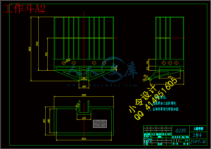
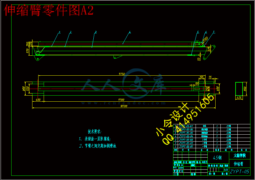
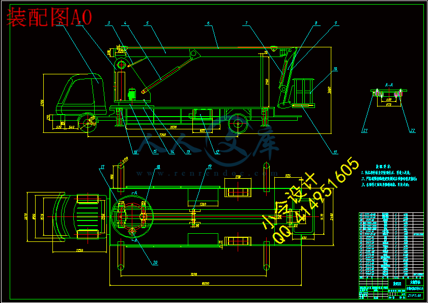
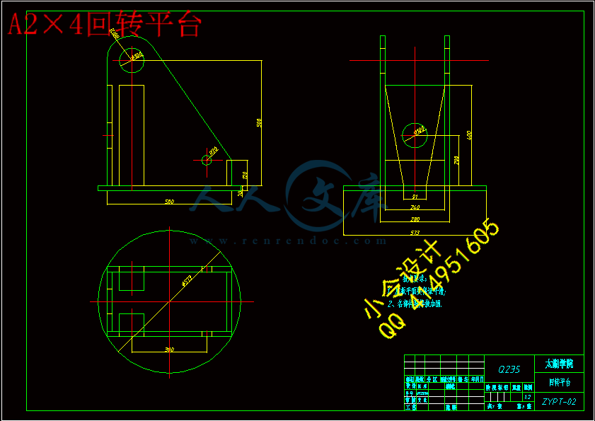
车载式高空作业平台的结构设计【7张CAD图纸+毕业论文】【答辩通过】

收藏

压缩包内文档预览:(预览前20页/共46页)
预览图 预览图 预览图 预览图 预览图 预览图 预览图 预览图 预览图 预览图 预览图 预览图 预览图 预览图 预览图 预览图 预览图 预览图 预览图 预览图
编号:436526    类型:共享资源    大小:5.04MB    格式:RAR    上传时间:2015-05-28 上传人:好资料QQ****51605 IP属地:江苏
45
积分
关 键 词:
车载 高空作业平台 结构设计
资源描述:

【温馨提示】 购买原稿文件请充值后自助下载。

[全部文件] 那张截图中的文件为本资料所有内容,下载后即可获得。


预览截图请勿抄袭,原稿文件完整清晰,无水印,可编辑。

有疑问可以咨询QQ:414951605或1304139763


摘  要


本课题首先对国内外高空作业车的发展进行了概括,提出了发展中的不足,简要介绍了高空作业车的组成,然后对目前国内生产技术不完善的混合臂和伸缩臂式高空作业车的关键结构进行了设计,同时对工作斗调平技术和液压系统等关键技术进行了研究分析。重点研究了伸缩臂的结构、运动特点,并对其进行了强度校核。根据高空作业车安全性要求高,工作幅度大,结构复杂等特点,提出了工作臂、副车架以及工作斗调平机构的研究设计方法。该课题以混合臂式高空作业车为研究对象,详细阐述了伸缩臂的结构设计、变形研究;副车架结构设计、工作稳定性分析;高空作业车的工作斗调平系统的研究分析;液压系统的设计计算。课题采用积分法对伸缩臂结构进行应力分析、变形分析。最后,对研究分析结果进行了试验和验证,将试验结果和理论分析结果进行了对比,通过对比分析进一步验证了本文提出的设计方法,对于同类型高空作业车研究计算,具有一定的参考价值。


关键词 :高空作业车;结构设计;调平系统研究;液压缸


Abstract

   This paper arranged as follows. The first part is the summary of the development of aerial working platform at home and abroad, and put forward some shortages during the development. There is a brief introduction of the component parts of the aerial working platform. This paper introduces a new design proposal of the domestic production technology of mixing arm and telescopic arm aerial working platform. Meanwhile, the analysis can also be seen in the working bucket leveling, hydraulic systems and other key technology. This paper mainly focuses on the telescopic structure, movement characteristics, and its strength check. According to the special requirements of aerial vehicles because of the high security, large in range and the complicated structure, the special design was used in the working arm, subframe and bucket leveling institutions. The subject is based on the study of mixing arm of aerial working platform. The subject describes the structural design of the telescopic boom in detail, and analysis the design of subframe structure design and the job stability. The aerial working platform bucket leveling system analysis and hydraulic syetem design are also mentioned here.the subject adopts integration method on the telescopic structure stress analysis and deformation analysis. The results of research and analysis are also compared in this part. The new design method is created through comparative analysis. And it is an useful guideline for the same type of aerial working platform.


Key words: Aerial working platform; Structure design; The research  of leveling system; The hydraulic cylinder


目  录

摘  要III

AbstractIV

目  录V

1 绪论1

1.1本课题的研究内容和意义1

1.1.1 课题研究背景1

1.1.2 课题研究的意义1

1.2 高空作业机械的国内外发展概况1

1.2.1 高空作业机械的国外发展状况1

1.2.2 高空作业机械的国内发展状况2

1.3 高空作业车的组成2

1.3.1 专用底盘2

1.3.2 工作臂架3

1.3.3 三维全旋机构3

1.3.4 电气与液压系统3

1.3.5 安全装置3

1. 4 课题研究的内容4

2伸缩臂结构分析5

2.1 伸缩臂的结构5

2.2 工况分析6

2.3 伸缩臂强度计算分析6

2.3.1 危险工况 1 计算7

2.3.2 危险工况 2 计算7

2.4 伸缩臂变形计算8

2.4.1 力学模型的建立8

2.4.2 弹性位移的计算9

2.4.3 计算结果12

2.5 伸缩臂强度校核12

2.5.1 计算基本臂臂的截面尺寸14

2.5.2对下臂进行正应力校核15

2.6 本章小结16

3 副车架结构及分析17

3.1 副车架结构17

3.2 支腿反力的计算17

3.3 转台回转系统21

3.4 本章小结22

4 工作斗调平机构的研究23

4.1 工作斗调平结构模型23

4.2调平机构液压系统25

4.3 本章小结26

5液压油缸的设计计算27

5.1 伸缩变幅油缸的结构27

5.2 伸缩变幅油缸的设计计算27

5.2.1 确定液压缸类型和安装方式27

5.2.2 确定液压缸的主要性能参数和主要尺寸27

5.3 本章小结31

6 结论与展望32

6.1 结论32

6.2 展望32

致  谢33

参考文献33

附  录33


1 绪论

1.1本课题的研究内容和意义

1.1.1 课题研究背景

现如今我国经济的飞速发展以及政府对基础设施建设的力度逐渐增大,高空作业平台的需求量不断增加,市场前景非常广阔。然而由于我国对于高空作业平台的研究开发起步较晚,对其核心技术掌握的不足以及加工工艺的落后等方面的原因,使得我国高空作业产品的使用功能、安全性等方面得不到充分的质量保证。通过对目前高空作业产品市场的发展趋势和广泛的市场研究,发现国内产品具有类型单一、设计粗糙等缺陷,无法满足很多特殊施工环境的要求[l],因此我国高空作业设备大多依赖进口。虽然国外产品功能完善、性能比较优秀,但是由于价格太高,对很多建设公司或者施工方来说成本占用比例过大,使得利润空间降低。因此,研发生产属于我国自主品牌的高性能的高空作业平台有着极其重要的经济价值和战略意义。                                                                                                                                                                                                                                                                                                                                                                                                                                                                                                                                                                                      

高空作业平台是用来运送工作人员和工作装备到指定高度进行作业的一种大型工程机械设备,并广泛用于电力、路灯、市政、园林、通信、机场、造(修)船、交通、广告、摄影等高空作业领域。国家标准GB3608.93《高处作业分级》规定:VL在坠落高度基准面2m以上(含2m)有可能坠落的高处进行作业,都称为高处作业。"因此为保障工人在高处作业的安全性,出现了越来越多的高空作业设备,然而随着科技的发展和人们对使用要求的增加,传统的高空作业设备已经无法满足人们的需求,专用高空作业平台技术在最近几十年来得以快速发展。

1.1.2 课题研究的意义

随着社会的进步和发展,人们对于产品的人性化要求越来越高,因此在产品结构设计的过程中应坚持人性化思想[2],以人机工程学原理为指导充分分析研究产品各方面因素,提出相应的设计方案。本课题在充分研究产品性能的基础上,对高空作业平台的功能模块进行了充分的结构分析,并根据其各方面的特殊性提出了相应的设计要求,指导其结构设计,因此课题研究的意义主要体现在以下几个方面:

(1)通过本课题的研究,掌握混合臂高空作业车金属结构件的设计理论和分析方法,了解高空作业车结构件的工作规律,从而达到减轻自重、优化结构、提高可靠性的目的,为研制系列伸缩臂、混合臂高空作业车奠定良好的基础。

(2)对车载式高空作业平台进行模块划分,将其分为工作平台、操作系统、运动系统和支持系统几个部分进行分别研究,对每一部分进行充分的结构分析,结合产品的相关标准和设计原则,对其结构设计进行指导。在课题的研究过程中结合产品的使用功能,通过计算机建模,在保证实现基本功能的基础上,总结相应的外观设计理论,以指导后续系列产品的结构设计,同时对于其它机械产品的外观设计研究具有一定的理论指导意义。

1.2 高空作业机械的国内外发展概况

1.2.1 高空作业机械的国外发展状况

高空作业车发展起步较早的欧美等发达国家和地区,从20世纪20年代就开始研制,发展历史久远,生产技术也很成熟,具有生产技术水平高、作业车的作业高度大、规格齐全、结构型式丰富、功能多样等优点。总体来看,技术和市场均已很成熟,产品能够进行高空作业、抢险、救援、消防等复杂工作,作业平台的最大载荷可达500kg,最大作业高度已经超过100m,这是我国目前无法设计达到的高度,同时具有各种安全保护措施,很好的保障了工人的安全。大型产品特点是科技含量高、研制与生产周期较长、投资大、市场容量有限,但市场竞争相对较少,产品的利润相对较高。如美国Genie公司、JLG公司和法国HAULOTTE公司在高空作业平台产品都形成了系列化,与此同时,产品更新换代的周期明显缩短。这大大提高了企业在国际市场中的竞争能力和企业的抗风险能力。

1.2.2 高空作业机械的国内发展状况

我国产品在质量和性能上与国外优秀产品虽然存在一定的差距,但是随着科技的不断发展,产品的功能和性能已经逐渐趋于同质化[3],因此必须通过对我国高空作业机械产品与国外先进企业产品进行分析和比较,找出发展问题的之所在,并提出相应的解决方案。我国高空作业平台的使用范围与国外相比来说还比较窄,使用较多的有路灯、交通、园林等部门,而在有发展前途的电力、电信及有线电视系统使用较少,市场远远没有挖掘和培育出来[3]。目前市场上的主要产品仍然是体积教大,对作业场地要求较高的拖车式或车载式高空作业车,而我国市场上的车载式高空作业车多为价格昂贵的国外进口产品或中外合资企业的产品,我国本土研发的设备极少,因此我们开发研制出拥有自主产权的高性能车载式高空作业平台具有很强的发展战略意义。

我们应提高工程设计效率和品质,节约设计成本,缩短设计周期[4-5]。而传统设计在设计一个工程结构的时候,首先要采用类比方法确定设计方案的初稿,然后对其结构进行分析,画出图纸,然后对重要部件进行强度的校核,并根据校核的结果重新修改设计方案,一般往往要进行多次分析校核和调整才能得到优秀的设计方案。这种设计方法的设计周期长、代价高、效率低,且所得到的方案多数不是最优方案[6-7]。只有加大行业技术创新力度,开发先进的高空作业机械,满足用户的差别化和个性化需求,为用户精细化服务,才能提高中国产品的市场竞争能力。

在我国实际工作过程中,人们对于安全性和劳动条件提出了更高的要求,尤其是在高空作业中,原始的脚手架、吊篮等安全系数较低的工作方式将会越来越少,而对于高空作业机械的需求必将越来越多[8]。另一方面,中国造船业逐渐成为世界第一,对于大型车载式高空作业平台的需求急剧增加。据不完全统计,仅中国造船行业在2009年约需六七百台高空作业平台[9],这一市场之前基本都被国外品牌占据。因此,研发生产属于我国自主品牌的高性能的高空作业平台有着极其重要的经济价值。虽然国内产品近些年来发展较快,但从整体上看,无论是技术上还是应用上都落后于国外同类产品,与国外先进产品相比还有较大的差距。

1.3 高空作业车的组成

高空作业车正常进行作业,需要由专用底盘、工作臂架、三维全旋机构、液压系统、电气系统和安全装置等部分组成,性能如下。

1.3.1 专用底盘

专用底盘。由发动机、车架、行走机构、转向机构等组成。考虑到工作可靠性、噪声、排放等方面综合要求,优选康明斯B3.3~C60型工程机械专用柴油发动机,该发动机为直列4缸水冷、自然吸气发动机,带全程调速器,运行平稳,具有热效率高、比油耗低、排放污染少等特点。由于台车行驶速度低,综合考虑作业安全性和经济性,车架采用刚性连接式,不设悬架机构,轮胎选用高负荷实心橡胶轮胎。

1.3.2 工作臂架

工作装置由回转台、工作臂架、伸缩软链等组成。回转台通过回转支承安装在车架上,由回转机构驱动,可实现360°全回转。回转机构包括行星减速机、常闭式制动器、液压马达等构成,与回转支承采用外啮合传动方式。

1.3.3 三维全旋机构

三维全旋机构设备或系统的安装位置一般由标高和方向2个参数确定。由于要求被举升物体在空间相互垂直的3个方向可以进行独立旋转,使物体可以获得任意安装角度,因此设计了三维全旋机构,即在水平和竖直方向设置±90°。旋转机构俯仰方向转角可以通过臂架变幅进行,微调由调平油缸实现,不再设单独机构,从而减少机构设置。

1.3.4 电气与液压系统

液压系统采用1台变量柱塞泵和1台定量齿轮泵供油,由发动机驱动。变量泵为行走、转台回转、臂架变幅和臂架伸缩供油,齿轮泵为行走转向机构、工作装置摆动、工作装置翻转、工作装置夹紧和调平机构微调供油。由变量泵供油的动作采用比例阀进行控制,以便精确进行速度调节,其它动作由于速度低、流量小,直接采用电磁换向阀进行控制。液压系统内设有安全溢流阀、液压锁等安全装置。

内容简介:
编号无锡太湖学院毕业设计(论文)相关资料题目: 车载式高空作业平台的结构设计 信机 系 机械工程及自动化专业学 号: 0923104学生姓名: 张 璐 指导教师: 黄敏(职称:副教授 ) (职称: )2013年5月25日目 录一、毕业设计(论文)开题报告二、毕业设计(论文)外文资料翻译及原文三、学生“毕业论文(论文)计划、进度、检查及落实表”四、实习鉴定表无锡太湖学院毕业设计(论文)开题报告题目: 车载式高空作业平台结构设计 信机 系 机械工程及自动化 专业学 号: 0923104 学生姓名: 张 璐 指导教师: 黄敏 (职称:副教授) (职称: )2012年11月25日课题来源自拟科学依据(包括课题的科学意义;国内外研究概况、水平和发展趋势;应用前景等)(1)课题科学意义高空作业平台是用来运送操作人员和工作设备到指定高度进行作业的特种车辆。随着城市化进程的加快,市政建设、城市电力、装饰物等各种养护作业需要大量的高空作业装备。高空作业平台作为一种系列化的工程机械设备,还广泛应用于船舶、建筑、消防、港口货运等行业。随着高空作业领域的不断扩展,对高空作业平台的需求将会越来越大,对高空作业平台的举升高度的要求也越来越高。因此,对高空作业平台的工作可靠性、平稳性、安全性等要求将越来越高。高空作业平台在各种复杂的工况下工作,其伸缩臂要完成各种动作,除了机器本身的自重和作用反力之外,还有吊篮中传来的冲击载荷以及运动载荷,要保证这种大型机器的正常工作,各构件的动态特性以及工作平稳性成为关心的主要问题。与一般的起重运输机械相比,高空作业平台虽然载重量要小得多,但作为高空载人作业设备,应具有更高的安全性和可靠性。因此,有必要不断深入地探讨计算机建模、计算与仿真方法,将CAD、CAE技术应用于设计中,提高设计计算与实际情况的符合度,提高预测对象工作能力的准确性,提高国内高空作业平台自主设计开发技术水平。(2)高空作业平台的研究状况及其发展前景我国高空作业机械的生产于上世纪70年代末开始起步,发展较快,根据中国工程机械工业协会对会员单位初步统计,2007年我国高空作业平台行业会员单位产量为2808 ,2008年达到了4045台,高空作业平台产品2008年比2007年增加了1237台,增长率为30.58%;2008年销量达到了3475台,比2007年增加了727台,增长率为20.92%;高空作业平台产品仅2008年19月就出口了2180台,比2007年增加了1605台。行业一些骨干企业通过近几年的技术改造,生产规模不断扩大,形成了有各自特色的系列产品,各项经济指标逐步上升,经济效益也逐年提高。国内高空作业平台行业近年来取得了较好的发展,主要表现在以下几个方面:(1)产品市场占有率进一步扩大;(2)产品种类和数量不断增加;(3)产品性能进一步提高;(4)新产品的开发推动了行业技术,利用自己的技术优势和设备优势,开发了许多本行业产品,推动了行业技术的进步。 研究内容了解高空作业平台的工作原理,国内外的研究发展现状; 完成车载式高空作业平台的总体方案设计; 完成有关零部件的选型计算、结构强度校核及液压系统设计; 熟练掌握有关计算机绘图软件,并绘制装配图和零件图纸,折合A0不少于2.5张; 完成设计说明书的撰写,并翻译外文资料1篇。拟采取的研究方法、技术路线、实验方案及可行性分析(1)技术路线首先根据高空作业车的特殊性对其色彩、造型等方面的设计需求进行分析,从整体上把握其设计原则;然后对不同的功能区域进行单独的研究分析,总结出每一部分符合工程学要求的设计理论;最后将整体的设计分析和每一部分的设计相结合,寻找有效的结合点并进行统一协调,最终设计出高质量、高档次的产品。(2)研究方法 测试出典型工况下变幅缸和上、下平衡缸的位移,获得大量的实验数据。 对实验数据进行分析处理,为建立高空作业平台工作机构动力学模型、进行仿真与分析作了必要的准备。(3)实验方案 对工作臂进行有限元分析的方案有3个:将整个工作臂作为一个整体模型进行计算;将工作臂分成一、二、三节臂单独建模,分别计算。利用积分法对结构进行强度、刚度分析。 研究计划及预期成果研究计划:2012年10月28日-2012年11月16日:学习并翻译一篇与毕业设计相关的英文材料2012年11月20日-2013年1月20日:按照任务书要求查阅论文相关参考资料,填写毕业设计开题报告书。2013年1月25日-2013年2月10日:填写毕业实习报告。2013年2月20日-2013年3月10日:按照要求修改毕业设计开题报告。2013年3月19日-2013年3月30日:根据开题报告完成任务书。2013年4月1日-2013年4月30日:完成总装图及零件图的绘制。2013年4月30日-2013年5月25日:毕业论文撰写和修改工作。预期成果:我国市场前景广阔,产品质量性能逐渐满足要求,因此产品的发展必须由单纯的追求技术上的完善,转向产品外观质量的提高,放到与技术改进放到同等重要的位置,通过本课题的研究,产品必定以合理的色彩以及人性化的结构方式提高自己的附加值,吸引到更多地客户,加大自己产品的市场占有率,提高在行业中的竞争力。特色或创新之处 本课题采用实体建模的方式对设计结构进行强度分析。 利用积分法对结构进行强度、刚度分析,其结构比常规的解析法更准确、可靠。已具备的条件和尚需解决的问题 实验方案思路已经非常明确,已经具备使用积分法进行强度校核的能力。 液压系统的研究还不够完善。指导教师意见 指导教师签名:年 月 日教研室(学科组、研究所)意见 教研室主任签名: 年 月 日系意见 主管领导签名: 年 月 日中文译文混合动力驱动车辆安装高空作业平台的控制策略 Janusz Krasucki a, Andrzej Rostkowski a, Lukasz Gozdek b, Micha Barty b,a Construction Equipment Research Institute, Napoleona 2, 05-230 Kobyka, Polandb Warsaw University of Technology, Institute of Automatic Control and Robotics, Boboli 8, 02-525 Warsaw, Poland摘要本文提出的发展过程即假设,建造,模拟和分析混合动力驱动车辆安装高空作业平台的控制策略。特别注意的是支付控制系统策略的发展,确保适当的能源再生,通过电化学形式储存能量。控制策略是围绕上下分层控制系统的概念建立起来的。高空作业平台的高程控制被假定为控制系统的主要目标。控制系统的第二个目标是制定明确的跟踪和保持在预定义的范围内的可再充电的电化学蓄电池的充电水平。在Matlab-Simulink环境下开发控制系统的仿真模型。控制系统仿真的示范性成果被一个液压动力结构驱动安装在特殊车辆MONTRAKS上的高空作业平台例子所显示。关键字:控制策略,混合动力驱动,能量恢复,环境的保护,模糊逻辑从这篇文章中的图和表:如图1所示.MONTRAKS 3PS的专用车 1.介绍 减少车辆的废气排放一直是多年的研究目标,部分是迫于日益严格的环保立法。在1997年12月的第三届缔约方会议通过的“京都议定书”,旨在减少相比于1990年的温室气体排放量(GHG)平均水平的5。2005年2月16日由俄罗斯批准后生效。 作为一个用于减少温室气体排放,提高燃油经济性和能源效率的装置,混合动力系统正在受到关注。 混合驱动汽车市场动态的增长已经多年。现代,有11个大型汽车制造商用于交付或深入发展混合动力驱动型的车辆。即使这些车商主要是专供乘用车部分,应当强调的是他们进行了显着的努力,从而实现了混合动力驱动卡车,送货车和公交车1,2。 West Start-CALSTART3,一个先进的运输技术财团,在美国陆军国家汽车中心(NAC)的支持下,组织一部分混合动力卡车用户论坛(HTUF)计划试点项目,以加快和协助混合商业化。根据制定的CAL-START的预测,混合驱动车的市场份额在2010年将达到约9的增长,2020年将达到近18.5的增长。 还有重型机器和特殊用途车辆,都是实现混合动力驱动的解决方案可能出现的对象。但也有一些疑惑,该应用程序在经济上是否是可行的。考虑到乘用车,在有关环保法规的制定下,需要重要的角色扮演“规模的影响”。在重负荷机器的情况下,高空作业平台的挑选和携带移动式起重机专用车辆的升降设备,应考虑其在混合动力解决方案中的应用驱动与操作制约和应用。 在许多情况下,该类机械的工作条件强烈限制或甚至消除燃烧的应用引擎。特别是封闭的空间领域,如工厂商店,仓库,本质安全区等。当前实现柴油 - 电力驱动,可大大推广使用该种设备。另一方面,和其他用于加工的市政服务工程在人口高度密集的区域在夜间(街道喷雾器人士,垃圾车,电车的牵引网络服务车辆等)的公共服务领域相比,是非常独特的。经常由市民报道,有关于服务项目问题的解决是关乎于柴油发动机产生的噪声的水平。 一个由瓦拉公司4 设计电池供电的起重机路线的例子,就如何满足不断增加的法规控制室内起重作业时的环境条件,最近对混合解决方案将报盘延期。另一例子是由伊顿公司5,6研究的,用于高空作业平台设备的中型卡车的混合动力系统。伊顿公司从2007年8月开始使中型混合动力系统的各种应用商业化,例如一个:电信和直辖市,城市配送,拒绝,城市公交大巴,挑选和携带等。 一种混合动力车辆,被定义为一个具有一个以上的源功率。虽然几种不同类型的混合解决方案虽已在过去被考虑,但目前仍在接受进一步的广泛研究,如混合动力电动汽车(HEV)1,它使用的电动机/发电机和电池组(或其他电存储设备)和机械混合动力汽车用飞轮来储存能量。混合液压的车辆(HHVs)2,车辆加速时的制动过程中它存储捕获的动能,并将其存储在液压气动蓄能器并返回能量传动系统。各个不同结构的混合驱动器(串行和并行)开发7,8。 混合电力系统维护传统的传动系体系结构,当添加一个能够提高发动机功率的电气时。 该系统的一个特点是它通常能够恢复在制动和储存时丢失的能量,并存储在电池中。存储的能量被用于改善燃油经济性和车辆性,只能为给定速度或用于操作车辆的电力系统。 混合动力传动系的控制比控制的ICE唯一的动力传动系要复杂得多。首先,需要在五种可能的模式(只有电动机,仅发动机,动力辅助,充电和再生)中确定最佳的操作模式。此外,当动力辅助模式或再充电模式被选择,则发动机功率和电机功率需要进行选择,以达到最佳燃油经济性,电池充电的平衡性和可操作性。随着增加的动力传动系的复杂性和需要实现多个的目标,最常用的是采用两级控制体系结构5。以下分析功率控制系统的优化:功率效率因素,燃油消耗和排放量已给出3,9,10。调查主要集中在车辆制动阶段的动能再生。 在本文中,设计一个动力管理控制系统,被描述成是一个配有液压高空作业平台(AWP)设备的专用汽车的驱动系统。AWP对该类型的车辆(被迫停止的占空比)处理应认真考虑负载势能的可回收性11,12。 混合驱动相比其他被提议的解决方案的主要优点是它是一个简单的驱动架构。它不同于已知的解决方案,那些广泛适用于私家车。经典方法(私家车)是需要完全重新设计动力传动系统。创新的方法对于特殊用途的车辆,只需要扩展经典的ICE驱动和扩展单元。扩展单元组成的电动机加上液压泵/马达。该解决方案允许区分热和电的功率流路径借助于液压子系统。然而,即使该解决方案不是简单的从功率流的角度出发,它任需求先进的控制系统策略。两层分层控制系统结构在本文中被提到。较低的控制水平是被本地经典的比例 - 积分 - 微分(PID)控制器所应用建造的。一个更高的控制水平是周围形成了一个模糊逻辑控制器(FLC),目的是对低水平本地控制器动态设置控制规则。2.目标系统的特点:一个专业的汽车MONTRAKS的(图1)打算利用市政通信服务维修和保养电车、有轨电车架空导线的系统,以及组装和拆卸的轨道部。图2结构的混合动力驱动单元理念:X - 活塞杆的位移,V - 活塞杆速度,p1- 活塞式压力,R 1 - 阀(8)的开关信号,p2的 - 供应压力,R2 - 切换阀(7)的信号- EM转速,U - 电池电压,I - 电池电流,n2 - ICE转速通常,这种类型的车辆在设计的基础上,为定期卡车的底盘配备了相应的工作配件。该设备是建立在架空工作嵌入式平台(AWP)(1)驱动的动臂(2)的端部的两个液压缸和液压回转马达(3)的集合。除了标准的道路上运行的轮胎,这些车辆的主要特征是可能在轨道上继续运行。具有低速液压马达驱动的额外的(4)轨道轮组实现了这一目标。 常常,牵引网络的维护和修理要耗时整晚,大都消耗在操作上。对于在维修工作的时间期间进行的,该车辆被停放;代替发动机连续不断地运行,并且驱动液压泵供应油给液压设备。在这个执行阶段周期,工作设备的功率需求很低 - 值不超过3,由于柴油发动机的额定功率2 接近它的低效率和重大排放量操作点的区域。同时,柴油机还产生特别恼人的噪音。上述缺点可以消除,例如通过引入额外的由一个电化学电池组成的电动机(EM)。在这种情况下,ICE将提供机械动力当车辆偏移操作区域时。停车时车辆的动力向EM以及可选的ICE工作设备索取,从而保持车辆平衡。讨论的混合动力驱动系统的结构示意图 2。用于电机的能源供给的是一组电化学蓄能器(5)。驱动设备单元的主要动力源是EM。电动机牵引参数由脉冲宽度调制器(6)控制。它可能扭转电动机运行到发电机模式。EM运行的液压泵(3)供应液压传动系统。 ICE,选择适当的工作点进行试转,成为第二液压泵(2)。液压油流量(2)和(3)在公共电源线上被添加在一起。液压切换阀(7)和(8)重定向油流量在干线电源上通过,要么储罐溢流到油箱阀或液压缸下活塞的腔室(9)。活塞缸(9)控制仰角臂(10)和间接高空作业平台部(11)的位置。很明显,气缸(9)控制负载的势能Q从而影响平台的提升或降低。图3 结构的控制系统,概念:sp xp -定位点的位置。光伏xp -实际值的位置;e xp -用位置控制误差;sp vp -定位点取消或降低速度的实际工作压力;光伏vp -实际价值,用速度;sp SOC -定位点的电池SOC;太阳能光伏电池SOC -实际价值的电池SOC;pv p1 -实际价值的压力p1;光伏p2 -实际价值的压力p2;OUT2 - PID控制器的输出。 图4 用隶属函数的位置控制误差以下几个阶段是加以区别的占空比混合动力驱动单元:SPL阶段 - 提升的AWP,SPD阶段 - 较低的AWP,SPP阶段 - 停车的AWP。在SPL阶段,由于气缸(9)的活塞式运转以及适当的吊杆上升运转,油流的添加或分化从泵(2)和(3)发生。万一流动减少,一个泵流量的一部分会被引导到主电源线,所述提供一部分驱动流量的泵(3)切换到电动机模式。在SPD阶段,油的流动方向在主油压供给线上发生变化,油运行泵(3)和机械耦合的电动马达(4)。在这两个阶段中它可能供给汽缸(9)通过油供给泵(3)由电动马达(4)驱动。电池充电(5)发生在SPP阶段。在此阶段中, AWP是被固定的,泵(3)是由石油供给给泵(2)所驱动的。3.控制策略在一般情况下,功率控制策略的主要目标是操作混合动力驱动时尽可能达到高的能源效率和低的排放量,同时保持指定车的辆性能13。控制系统的主要任务是最大限度地利用电力的混合动力驱动。MONTRAKS车辆的噪声水平和经济运行符合相对应的具体要求。这可以通过应用被建议的功率控制战略来实现。这一战略是基于通过控制一组电池的电荷(SOC)的状态从而操作AWP使其速度接近于所需的轨迹以及捕获有效的再生能量。因为它是唯一可能的,SPL和SPD占空比的阶段,应使用电力驱动。SOC是目前电池充电时瞬间可能存储在电池中最大比例的电荷。t = T时,可表示为:;其中:Q(t0)= Q max的最大容量的电池中,SOC(t0)= 1,i(t)的电池充电或充电电流。同时,一个电池组的SOC应控制在最小的SOC和最大的SOC之间,从而有效的得到能源的再生制动,使能量最少的丢失和对电池组的压力最小。最低和最高的SOC的标准是根据电池吸收再生能量的能力,并重新启动交通工具系统所确定的。在一般情况下,最小的SOC标准和最大SOC标准之间的差异,在于电池更多的可再生能源能有效地吸收。然而,对于在SOC标准内大跨度地操作可能会降低电池的使用寿命,同时受放电深度的影响。因此,SOC水平应适当地确定在最佳的最小和最大之间的水平SOC min, SOC max.。考虑到电池的充电和放电效率,本文的SOC范围被设置为0.3,0.8。发动机和电动机之间的流量分布可以通过驱动反应的程度(DOH)来确定:其中:PICE - 发动机的功率,PMOT - 电机功率。合并后的电源管理/设计优化问题可写为如下:在 SPL 和SPD 阶段出现最大值DOH其中:XSP(T)所需的AWP轨迹XPV(t)实际的AWP轨迹。为这个目的所设计出的控制系统的结构在图3。 图3示出的控制系统的结构。该控制系统由两个循环:- AWP的位置和速度的控制,- 控制电池组的SOC。每个回路可以控制电动机控制器。控制信号是受逻辑单元管理。它的目标是适当的时刻供应平稳切换的控制信号。AWP控制系统用一个级联结构来定位和控制速度。模糊控制器处理AWP的速度。其是从实际的和需求的平台位移来计算的。辅助控制器SP_vp的速度信号,被美联储以经典的PID控制器作为参考,把它与实际速度的平台PV_sp相比。第二控制回路电池的SOC保持在预定义的限制范围。这个循环是由PID控制器和逻辑单元组成的。 PID单元通过连续调节的液压阀位置控制管理电池的充电水平。3.1 AWP位置控制器AWP控制器的开发是基于已经开发的经典的级联控制器PID和控制器FLC。 FLC已经被选中,因为其适合控制的非线性,多领域的控制,并随时间变化有多种不确定因素3的工厂。该控制器有两个输入:一个AWP(SP_xp-PV_xp)控制位置误差,和一个AWP(PV_vp)测当前速度。 FLC为PID控制器的电动马达计算AWP的速度SP_vp的定位值。FLC14由三个基本的的块组成:模糊化,推断和非模糊化。控制器的输入是在模糊块被统一标准模糊化。事实上,模糊化把清晰的空间映射到模糊的空间。在这个过程中,对于适当的模糊值(模糊集),把每个鲜明的输入信号的每个样品被转变为一组数字信号理解为这个样本的隶属度。 同一的模糊化标准输入被供应到一个推理机。 推理机是在模糊输入,模糊逻辑规则和知识嵌入在规则库中(图6)进行模糊输出。该规则是根据相应的知识或通过依靠资料学习或从真实的后天获得或模拟实验建立起来的。模糊输出从推理机被转化成鲜明值通过依靠非模糊化程序。模糊化的过程中,专门三角形和梯形隶属函数已被使用。每个模糊AWP速度控制器的输入,都是依靠同一模糊化标准的7个隶属函数的装置来实现的(参见图4和5)。推理过程中应用的规则库描绘在图 6。规则库被设定定量的知识集。总共有49个规则已经被FLC论证。对于清晰度,规则库以彩色矩阵的形式显示。每个条目的矩阵对应于适当的模糊的输出(SP_vp);呈现在图6的右侧垂直条的形式 。图6 速度规则基于FLC使用,使用概念是表1中给出传统的重力中心14的方法已被应用于模糊输出的非模糊化。先进的FLC的控制面已示于图7中。正如上面提到的,从FLC输出供应到AWP的速率PID控制器。AWP的速率被控制输入到后续的控制系统,通过控制油压泵(图2)旋转的速度。速度控制器的设置经过精心调校,以确保非周期性过渡(不过冲),即使在分步激发的情况下(参见图10和11)。3.2 SOC控制器线性PID控制器的已被应用于控制电池的SOC(图3)。SOC的实际值从Ep被连续地估算。(1)使用电池电流测量。一个额外的控制单元允许用于驱动电动液压阀的线圈阀R1和R2。电动液压阀的控制信号,用于获得供应压力p2的测量,根据活塞压力P1,以及电池的电流和电压(I,U)。在提升阶段的AWP,所述的控制单元提供了的电动液压阀(7)和(8)的一个适当的激发。结果,根据气缸的滑阀腔的与主油压供给线连接。后一个AWP要求的位置达到时,阀(8)朝着它的中间位置驱动,这将完成的平台的移动。在这里,内燃机燃烧的能量可用于电池充电。在电池充电阶段,充电控制器还在控制压合液压缸的滑阀腔室。这防止不愉快情况,AWP的意外震摇所导致的负载变化。电动液压阀(7)将切换到位置,引导油从泵(2)到油箱在达到所要求的电池充电水平之后。从低级阶段的平台开始,控制单元再次切换阀(7),均衡的供应和根据活塞油的压力。紧随其后,阀(8)将被切换成上下移动的平台。势能平台在这一运动期间被转换成电的形式,并用于电池充电。 图7 控制表面的FLC3.3 无冲击切换系统模拟实验显示,在控制单元的操作模式切换期间会出现控制信号的逐步变化。这种现象应该被消除,因为它可能降低混合动力驱动的可靠性数据。例如,一个逐步改变的的控制信号,强制电动马达动态变化的旋转速度,导致压力在供油线摆动。一个特别小组已经开发,以避免突然变化的混合动力驱动控制信号的潜在影响。 “本单元的概念已被示于图 8。块P1,I1,D1分别表示:成比例的PID1控制器的加-积分 加-导数成分。控制器的主要部分是配有设置控制器输出初始值的输入配置。切换单元跟踪各自的输出:控制器PID1和PID2的OUT1和OUT2。在控制器输出切换的时刻,跟踪系统的设置输出的积分动作I1和I2的值满足下列条件:一)I1= OUT1切换到SOC控制器, 二)I2=OUT2时,切换到AWP速度控制器。控制误差值e切换的时刻(t = 0时)补偿辅助值e k,由校正单元生成。校正值e k从值E0= SP_vp-PV_vp下降到零值,在预定义的时间间隔t内。这意味着,OUT1和OUT2的值将等于在转换i.e. 控制值时对于直流电动机控制器的不会改变切换时刻。此操作可确保的切换电动机控制装置设定值时无冲击。后来t消逝i.e.= 0时,输入的PID1控制器er=e 。4.模拟调查 混合动力驱动在Matlab的Simulink环境下的分析模型的基础上已经进行了模拟调查。图11中给出。模型的调整参数部分是从专用汽车MONTRAKS的开发调查12所得的。开发的仿真模型具有的一般框图被示于图 9。 图8 交换单元的方块图 图9 MONTRAKS驱动装置模型的方块图 以下组的主要参数已被用于模拟调查:电解铅蓄电池标称容量Q nom=200Ah;额定电压U nom=48 V,DC电机:额定功率P nom = 5千瓦,标称转速速度n nom =2300 rpm,柴油机额定功率N = 120千瓦液压泵提供的标称单位QP =42.310-6 m3/rev液压缸活塞直径D = 10毫米,最大行程S =0.65米AWP的惯性负载:M= 680千克AWP允许以V max=0.5米/秒速度的提升/降低:电池充电的初级水平SOC(T0)= 0.8。 模拟调查被作为循环周期为T =18秒假设的职务执行的,以下是几个阶段:SPL阶段 - 解除平台H=1.6米,SPP阶段 - 停车平台,tp=5秒,SPD阶段 - 降低平台H=1.6米。提升和下降AWP速度的模拟结果已给定图10和11。图10. AWP 的速度在 SPL 阶段. 图11. AWP 的速度在SPD 阶段 如3.1节中提到的,速度设定值由FLC生成。在早期开始的平台提升阶段(图10)和更低的阶段(图11),当控制误差最大,FLC快速推动最大的输出值。在实际系统中,这可能造成阻尼以低振幅的速度振荡(参照图10)。 平台速度的设定值和实际值在平台运行的结束阶段会无效。这个合理的方法,保证了所要平台的位置。一个较低的平台改变电池的充电水平。在AWP的工作期间SOC的改变示于图 12。轻微电池放电过程被观察到在SPP阶段。这是由于由电动马达装载电池运行液压泵所造成的。在SPD阶段,可观察到SOC增加是由平台的势能转换和再生的。能量回收比率(在SPD阶段热能源的份额比上SPL阶段所使用的能源)以约36为例被考虑。图12 电池SOC改变占空比期间 建议配置电池放电的每一个责任周期是0.017。连续循环的模拟得出结论,SOC达到其最低值0.3在2920循环周期之后。这是相当于14.6 h工作时间,见图13。AWP的有效使用时间占整个工作周期时间74并达到2.5小时12。从而可以得出结论,即AWP的驱动电源只有在电池不过度放电时才能够供给的电动机。如下所述,为整个车辆的工作时间估计平均燃油消耗量可以降低约24。 图13 电池SOC下降5.结束语 一个用于混合动力驱动,由AWP速度控制器,AWP位置控制器和电池充电控制器组成的两级多输出控制系统结构,已经研制成功。该系统允许转移系统的工作点使其运动轨迹能达到最佳的节能效果区域。模拟混合动力驱动的调查结果,实验验证表明了所开发的控制系统的正确性。 取得的模拟结果已经制定了一个固定的基础,发展用于发展原型实验室控系统的调查。本文提出的控制系统结构可以考虑用在混合动力驱动器的应用程序中,其在占空比之后致动元件改变它的潜在能量。例如:叉车,高空作业平台,安装转盘的拖车,移动式起重机等。MONTRAKS需要增加现有的高空作业平台驱动器的投资,估计占车辆总成本的2。为进一步推广应用的技术经济可行性,研究报告应详细到每个个案。致谢 作者答谢在波兰教育部和高等教育部的资金支持下获得5 TO7C 0192:为市政工程发展建设环保的专用车和机器的电动机械动力传送单元。参考文献1 B.V. Arburg, Hybrid technology growing momentum, Hybrid Truck Users Forum,San Antonio, 2003 .2 J.S. Stecki, F. Conrad, P.L. Matheson, A. Rush, Development of a hydraulic drive for a novel hybrid diesel-hydraulic system for large commercial vehicles, 5-th JFPS International Symposium on Fluid Power, Nara, Japan, 2, 2002, pp. 425430.3 B. Baumman, G.Washington, B. Glenn, G. Rizzoni, Mechatronic design and control of hybrid electric vehicles, IEEE transactions on mechatronics, 55(1), 2000, pp.5872.4 http:/www.valla.co.5 C. Lin, H. Peng, J.W. Grizzle, J. Liu, M. Busdiecker, Control System Development for an Advanced-Technology Medium-Duty Hybrid Electric Truck, SAE International Truck & Bus Meeting & Exhibition, Fort Worth, TX, USA, SAE Paper 2003-01-3369,2003.6 R. Nellums, J. Steffen, S. Naito, Class 4 Hybrid Truck for Pick Up and Delivery Applications, SAE International Truck & Bus Meeting & Exhibition, FortWorth, TX,USA, SAE Paper 2003-01-3368, 2003.7 C. Chan, The state of the art of electric and hybrid vehicles, Proc. IEEE 90 (2) (2002)247275.8 M. Ehsani, Y. Gao, S.E. Gay, A. Emadi, Modern Electric, Hybrid Electric, and Fuel Cell Vehicles: Fundamentals, Theory, and Design, CRC Press, Washington D.C., 2004.9 J.B. Burl, J.E. Beard, Control Strategies for a Series-Parallel Hybrid Electric Vehicle,SAE 2001 World Congress, Detroit, SAE Paper 2001-01-1354, 2001.10 D. Choi, M. Im, H. Kim, An operation algorithm with state of charge recovery for a parallel-type hybrid vehicle, Proc. of the Institution of Mechanical Engineers, PartD, J. Automob. Eng. 217 (9) (2003) 801807.11 J. Krasucki, A. Rostkowski, Idea of application of electric drives in hydraulic power systems on example of actuating units of automotive crane MONTRAKS, (in Polish),Prz. Mech. 9 (2005) 1519.12 A. Rostkowski, J. Krasucki, M. Barty, The analysis of hydraulic driving system of special vehicle MONTRAKS in operating conditions, XX Conference on Problems of Heavy Duty Machines Development. Zakopane, Poland, 2007, pp. 269271, (in Polish).13 D.L. Buntin, J.W. Howze, A switching logic controller for a hybrid electric/ICE vehicle, Proc. of American Control Conference, Seattle, 2, ISBN: 0-7803-2445-5,1995, pp. 11691175.14 J.M. Mendel, Fuzzy logic systems for engineering, Proc. IEEE 83 (1995) 345377.15英文原文Control strategy of the hybrid drive for vehicle mounted aerial work platformJanusz Krasucki a, Andrzej Rostkowski a, ukasz Gozdek b, Micha Barty b,a Construction Equipment Research Institute, Napoleona 2, 05-230 Kobyka, Polandb Warsaw University of Technology, Institute of Automatic Control and Robotics, Boboli 8, 02-525 Warsaw, PolandThe development process i.e. assumptions, construction, simulations and analysis of a control strategy for thehybrid drive of the vehicle mounted aerial work platform is presented in the paper. Particular attention ispaid to the development of the control system strategy ensuring appropriate energy recuperation by makinguse of energy stored in the electrochemical form. The control strategy is built up around the concept of bilevelhierarchic control system. The elevation control of the aerial work platform is assumed as the primarygoal of the control system. The secondary goal of the control system is formulated in terms of tracking andkeeping the charging level of the rechargeable electrochemical accumulator in predefined limits. A control system simulation model is developed in Matlab-Simulink environment. Exemplary results of control system simulations are shown on the example of a hydraulic power unit driving aerial work platform mounted onspecial vehicle MONTRAKS.1. IntroductionThe reduction of vehicle emission has been an objective of research for many years; partly it is forced by increasingly stringent environmental legislation. The Kyoto protocol, whichwas adopted at the COP3in December 1997, is aimed to decrease the green house gas emissions(GHG) by an average of 5% referring to 1990 levels. It came into force on February 16, 2005 following its ratification by Russia.Hybrid systems are now gaining attention as a means for reducing GHG emissions by improving fuel economy and energy eficiency.Market for hybrid driven vehicles is growing up dynamically sincemany years. Contemporary, eleven large car manufacturers use to deliver or to intensively develop hybrid driven vehicles. Even that is mainly focusing on passenger cars segment, it should be stressed that the remarkable effort is undertaken to implement hybrid drives in the trucks, delivery vans and buses 1,2.WestStart-CALSTART 3, an advanced transportation technologies consortium, supported by U.S. Army National Automotive Center(NAC), organized the pilot program as part of its Hybrid Truck Users Forum (HTUF) program, to speed up and to assist hybrid commercialization. According to the forecasts elaborated by CALSTART,the hybrid driven trucks market share will grow reaching ca 9% in 2010 and near 18.5% in 2020.Still heavy duty machines and special purpose vehicles are the object of possible implementation for hybrid drive solution. However there are some doubts, if that application is economically feasible.Considering passenger cars,in respect of environmental regulations,important role plays the “effect of the scale”. In case of heavy duty machines, aerial work platforms, pick and carry mobile cranes or special vehicles with lift equipment, the application of hybrid solution is driven with operating constrains and application.For many cases, working conditions for that class of machinerystrongly limits or even eliminates the application of combustion engines. In particular that is case of closed space areas such as factory shops, warehouses, intrinsically safe zones, etc. Here the implementation of diesel-electric drives could considerably extend possible use of that kind of equipment. Very unique and on the other side common area of services is municipal services and works used to be processed during night in the highly populated zones (street sprayer-sweepers,garbage trucks, tramway traction networks service vehicles, etc.). It is often reported by municipalities, that the issue to be solved for that services is the level of noise generated by diesel engine.An example on how to meet the ever-increasing regulations controlling environmental conditions during indoor lifting operations is the battery powered cranes line designed by Valla Corporation 4,which recently extended the offer for hybrid solution. Another example is a hybrid system investigated by Eaton Corporation 5,6for medium trucks with optional aerial work platform equipment.Eaton began commercializing its medium-duty hybrid system in August 2007 in a wide variety of applications such a: telecommunications and municipality, city delivery, refuse, city transit bus, pick andcarry and so on.A hybrid vehicle is defined as one that has more than one source of power. Several different types of hybrid solutions have beenconsidered in the past and are still undergoing extensive research, Fig. 1. Special purpose vehicle MONTRAKS 3PS.such as Hybrid Electric Vehicles (HEVs) 1, which use a motor/generator and battery packs (or other electrical storage devices) and mechanical hybrids which use flywheels to store energy. Hybrid Hydraulic Vehicles (HHVs) 2, which store kinetic energy captured during braking events and store it in hydro-pneumatic accumulators and return energy to driveline during vehicle acceleration. Various different structures of hybrid drives (serial and parallel) have been developed. 7,8The hybrid electric system maintains conventional drive train architecture while adding the ability to enhance engine power withelectrical one.One feature of this system is its ability to recover energy normally lost during braking and store the energy in batteries. The stored energy is used to improve fuel economy and vehicle performance for a given speed or used to operate the vehicle with electric power only.The control of hybrid power trains is more complicated than the control of ICE only power train. First, one needs to determine the optimal operating mode among five possible modes (motor only,engine only, power assist, recharge, and regenerative). Furthermore,when the power assist mode or the recharge mode is selected, the enginepower and motor power needs to be selected to achieve optimal fuel economy, battery charge balance, and operability. With the increased power train complexity and the need to achieve multiple objectives, most often a two-level control architecture is adopted 5.Fig. 2. Structure of the hybrid drive unit. Notion: x piston stem displacement, v piston stem velocity, p1 under piston pressure, R1 switching signal of valve (8), p2 supply pressure, R2 switching signal of valve (7), n1 EM rotational speed, U battery voltage, I battery current, n2 ICE rotational speed, OUT setpoint of electric motor controller.Fig. 3. Structure of the control system. Notion: SP_xp Setpoint of the AWP position. PV_xp Actual value of the AWP position. e_xp AWP position control error. SP_vp Setpoint of the lifting or lower velocity of the AWP. PV_vp Actual value of the AWP velocity. SP_SOC Setpoint of the battery SOC. PV_SOC Actual value of battery SOC. PV_P1 Actual value of the pressure p1. PV_P2 Actual value of the pressure p2. OUT1, OUT2 Outputs of PID controllers.The analysis of power control systems optimizing: power efficiency factors, fuel consumption and emissions has been given in3,9,10. Investigations have been mainly focused on the possibility of kinetic energy recuperation in the phase of vehicle braking.In this paper, the design of a power management control system isdescribed for a hybrid drive system of special purpose vehicle with hydraulic aerial work platform (AWP) equipment. For that type of vehicles (stop-and-go duty cycles) the potential energy of the load being handled with AWP should be seriously considered as recyclable 11,12.The major advantage of the proposed hybrid drive over othersolutions is a simple drive architecture. It differs from known solutions, thosewidely used in personal cars. The classic approach (personal cars) needs full redesign of power transmission system. The innovative approach for the special purpose vehicles requires only extension of classic ICE drive with extension unit. Extension unit is composed of electricmotor coupledwith hydraulic pump/motor. That solution allows to differentiate the power flowbetween the thermal and electrical path with help of hydraulic subsystem. However, even that solution is not straightforward from the point of view of power flow, it demands for advanced control system strategies.Two-layer hierarchical control system architecture is considered in this paper. A lower control level is built by application of local classic proportional-integral-derivative (PID) controllers. A higher control level is developed around a fuzzy logic controller (FLC) with the intention of dynamically setting out control rules for lower level local controllers2. Characteristics of the target systemA specialized automotive vehicle MONTRAKS (Fig. 1) is intended for repairing and maintenance of tram and trolley-bus overhead wire system, assembling and disassembling of rail track sections and is exploited by the municipal communication services.Such types of vehicles are usually designed on the bases of regular trucks undercarriage equipped with appropriate working accessories. The equipment is built up around the aerial work platform (AWP) (1) embedded at the end of the boom (2) driven by the set of two hydraulic cylinders and hydraulic swing motor (3).Besides a standard road running on the tires, the major feature of these vehicles is the possibility to move on rail run. That is achieved with additional set of rail wheels (4) which are driven with low speed hydraulic motors.As often as not, maintenance and repairing of the traction networks take place throughout the night, and these are time consuming operations. For the period of the time that repair work is carried out, the vehicle is parked; instead of the engine is continuously running and driving the hydraulic pump which is used to supply oil to the hydraulic equipment. In this phase of duty cycle, a power demand from the working equipment is low does not exceed 3% value of engine rated power 2, due to that the diesel operation point approaches the regions of its low efficiency and significant emissions. Simultaneously, the diesel generates particularly bothersome noise.Disadvantages mentioned above may be eliminated for instance by introducing an additional electric motor (EM) powered by an electrochemical battery pack. In this case, the ICE will delivermechanical power when the vehicle moves from/to its operation area. While parking the vehicles power demand from the working equipment will be balanced from the EM and optionally from the ICE.The structure of discussed hybrid drive is shown in Fig. 2Energy for the motor is supplied from a set of electrochemicalaccumulators (5). The primary power source of the equipment drive unit is the EM. Motor traction parameters are controlled by the pulse width modulator (6). It is possible to reverse the motors operation into generator mode. The EM runs the hydraulic pump (3) supplying the hydraulic actuation system. The ICE, running in the appropriate chosen operating point, drives the second hydraulic pump (2).Hydraulic oil flows frompumps (2) and (3) are added together in the common supply line. Hydraulic switching valves (7) and (8) redirect the oil flow in the main supply line either to the tank via overflow valve or to the under piston chamber of the hydraulic cylinder (9).The piston stemof the cylinder (9) controls the elevation angle of the boom (10) and indirectly the position of AWP (11). It is obvious that the control of the cylinder (9) influences the potential energy of load Q while the platform is lifting or lowering.The following phases are to be distinguished in the duty cycle of thehybrid drive unit: SPL phase lifting of the AWP, SPD phase lower of the AWP, SPP phase parking of the AWP.In SPL phase, as a result of movements of the cylinders (9) piston and appropriate boom lifting movements, the addition or differentiation of oil flows from pumps (2) and (3) takes place. In case of subtraction of flows, one part of the pump flow (2) is directed to the main supply line and the reminder part of flow drives the pump (3) switched into motor mode. In SPD phase, the direction of oil flow in the main hydraulic supply line changes, oil runs the pump (3), and the mechanically coupled electric motor (4). In both phases it is possible to supply cylinder (9) by the oil delivered by the pump (3) driven by electric motor (4). Charging a battery (5) occurs in the SPP phase. In this phase, the AWP is fixed, and the pump (3) is driven by oil provided by the pump (2).Fig. 4. Membership functions of the AWP position control error.3. Control strategyIn general, the main objective of the power control strategy is to operate the hybrid drive with possible high energy efficiency and low emissions while maintaining specified vehicle performance 13.Maximal use of electric power is the main task of the hybrid drive control system. This corresponds with specific requirements for noise level and economic operation of MONTRAKS vehicle.This can be achieved by applying of the proposed power control strategy. This strategy is based on operation of AWP velocity closed to required trajectory and effectively capturing of the regenerative energy by controlling the state of charge (SOC) of a battery. As it is only possible,the electric drive should be used in SPL and SPD phases of duty cycle.SOC is the ratio of present charge of a battery to the maximum charge that can be possibly stored in the battery and in time instantt=T may be expressed as:;where:Q(t0)=Qmax maximal capacity of the battery, SOC(t0)=1,i(t) battery charging or recharging current.Meanwhile, the SOC of a battery should be controlled between a minimum SOC and a maximum SOC to obtain regenerative braking energy effectively with the least amount lost and stress on the battery.The minimum and maximum SOC levels are determined according tothe ability of a battery to absorb regenerative energy and to restart vehicle systems. In general, the larger the difference between the minimum SOC level and the maximum SOC level, the more regenerative energy a battery can effectively absorb. However, the larger span of operating SOC levels may reduce the batterys life, which is affected by the depth of discharge. Hence, the SOC levels should be appropriately determined between optimal minimum and maximum levels SOCmin, SOCmax. Considering the battery charging and discharging efficiency, the SOC range is set to 0.3, 0.8 in this paper. The power flow distribution between engine and electric motor may be defined through degree of hybridization (DOH) of the drive:where: PICE engine power, Pmot motor power.The combined power management/design optimization problem can be written as follows: where:XSP(t) 2 desired AWP trajectoryXPV(t) 2 actual AWP trajectory.A structure of the proposed control system for this purpose is given in Fig. 3.Fig. 3 shows the structure of the control system. The control system consists of two loops: control of the AWP position and velocity, control of the SOC of battery pack.Each loop may control electric motor controller. Control signals are governed by the logic unit. It is aimed to provide smooth switching of control signal for appropriate time instants. Control system for AWP positioning and velocity control has a cascade structure. Fuzzy controller processes the velocity of the AWP. It is calculated from the real and desired platform displacement. Velocity signal from the auxiliary controller SP_vp is fed as the reference to the classic PID controller and it is compared with actual velocity of the platform PV_sp. The second control loop keeps the SOC of battery in predefined limits. This loop consists of PID controller and logic unit. PID unit controls the level of charge of the battery through continuous adjustment the hydraulic valves positioning.Fig. 5. Membership functions of the AWP velocity.3.1. AWP position controllerA controller of the AWP has been developed based on the cascade of classic PID controller and FLC. The FLC has been chosen because of its suitability for control of nonlinear, multiple-domain, and timevarying plant with multiple uncertainties 3. This controller has two inputs: a control error of the AWP postion (SP_xpPV_xp), and acurrent velocity of the AWP (PV_vp). The FLC calculates setpoint value of the AWP velocity SP_vp for the PID controller of the electric motor.The FLC 14 consists of three basic blocks: fuzzyfication, inference and defuzzyfication. Inputs of the controller are fuzzyfied in the fuzzyfication block. In fact, fuzzification maps the space of crisp values onto the space of fuzzy ones. In this process, each crisp sample of each input signal is transformed into the set of numbers interpreted as the membership degrees of this samples to the appropriate fuzzy values (fuzzy sets). Fuzzyfied inputs are fed to an inference machine. The inference machine makes fuzzy outputs based on: fuzzy inputs, fuzzy logic rules and knowledge embedded in the rule base (Fig. 6). The rule base is created based on the appropriate knowledge or by means of learning from data or is acquired from real or simulation experiments. Fuzzy output from the inference machine is transformed into the crisp value by means of defuzzyfication procedure. Exclusively the triangle and trapezoidal membership functions have been used in the process of fuzzyfication. In fuzzy AWP velocity controller each input was fuzzyfied by means of seven membership functions (see Figs. 4 and 5).The rule base applied for the inference process is depicted in Fig. 6. Rule base is assumed as the set of quantitative knowledge. A total of 49 rules have been formulated for the FLC. For the clarity, the rule base is displayed in the form of colored matrix. Every entry to the matrix corresponds with the appropriate fuzzy output (SP_vp); that is presented in the form of vertical bar in the right side of Fig. 6. Conventional, center of gravity 14 method has been applied for the defuzzyfication of fuzzy output. A control surface of developed FLC has been presented in Fig. 7. As mentioned above, the output from the FLC is fed to the AWP velocity PID controller. Velocity of the AWP is controlled in the follow-up control system by controlling rotational speed of the hydraulic pump (Fig. 2). Settings of the velocity controller have been carefully tuned to ensure aperiodic transition (without overshoots) even in case of stepwise excitation (see Figs. 10 and 11).3.2. SOC controllerThe linear PID controller has been applied for the control of the batterys SOC (Fig. 3). The actual value of SOC is continuously estimated fromEq. (1) making use of the measurements of the battery current. An additional control unit allows for driving the coils of electro-hydraulic valves R1 and R2. Control signals for the electro-hydraulic valves are obtained from the measurements of supply pressure p2, under piston pressure p1, and current and voltage (I, U) of the battery.Fig. 6. The rule base of the AWP velocity FLC. Notion used is given in Table 1.Fig. 7. Control surface of the FLC.In the lifting phase of the AWP, the control unit delivers an appropriate excitation for the electro-hydraulic valves (7) and (8). In outcome, the under piston chamber of the cylinder is connected with the main hydraulic supply line. After a demanded position of the AWP is reached, the valve (8) will be driven towards its neutral position, which will finish the movement of the platform. Here, the energy of the combustion motor may be used for battery charging. In the battery charging phase, the charging controller controls also the pressure in the under piston chamber of the hydraulic cylinder. This prevents an unpleasant situation of accidental spurious jerking of the AWP in case of the incidental load changes. The electro-hydraulic valve (7) will beswitched to position that directs oil from the pump (2) to the tank after reaching the demanded battery charging level. At the beginning of the lower phase of the platform, the control unit again switches on the valve (7), which equalizes the supply and under piston oil pressures. Just after that the valve (8) will be switched on causing down movement of the platform. Potential energy of theplatform during this movement is converted to the electrical form and is used for battery charging.3.3. Shock-free switching systemSimulations have shown that during switching of the operation modes of the control unit stepwise changes of the control signal may appear. This phenomenon should be eliminated because itmay lower the reliability figures of the hybrid drive. For example, a stepwise change ofthe control signal forces dynamic changes of the rotational speed of the electric motor, which results in pressure swinging in the oil supply lines. A special unit has been developed to avoid potential influences of the sudden changes of the control signal in the hybrid drive. The concept of this unit has been presented in Fig. 8. Blocks P1, I1, D1 represent respectively: proportional plus-integralplus- derivative constituents of the PID1 controller. An integral part of the controller is additionally equipped with the input for setting of initial value of the controller output. The switching unit tracks respective outputs: OUT1 and OUT2 of controllers PID1 and PID2. In the moment of switching of controller outputs, the tracking system sets outputs of integral actions I1 and I2 to the values that satisfy the following conditions:a) I1=OUT1 when switching to the SOC controller,b) I2=OUT2 when switching to the AWP velocity controller.The control error value e in a moment of switching (t=0) is compensated by auxiliary value ek, generated by a correction unit. The correction value ek drops down to zero value in the predefined timeperiod t starting from value e0=SP_vpPV_vp. This means that OUT1 and OUT2 values will be equal in the moment of switching i.e. the control value for DC motor controller will not change in the moment of switching. This action ensures shock-free switching of the motorcontroller setpoint value. After time t elapses i.e. ek=0, the input of the PID1 controller er=e.4. Simulation investigationsSimulation investigations of the hybrid drive have been carried out in the Matlab-Simulink environment based on the analytical models given in 11. Parameters used for model tuning were acquired partly from exploitation investigations of the specialized vehicle MONTRAKS12. A general block diagram of the developed simulation model has been shown in Fig. 9.The following set of the main parameters have been used for simulation investigations: electrochemical lead battery: nominal capacity Qnom=200 Ah;nominal voltage Unom=48 V, DC electric motor: nominal power Pnom=5 kW; nominal rotational speed nnom=2300 rpm, diesel nominal power N=120 kW nominal unit delivery of hydraulic pumps qp=42.3106 m3/rev hydraulic cylinder: piston diameter D=10 mm; maximal strokes=0.65 m mass load of the AWP: m=680 kg permissible velocity of lifting/lower of the AWP: Vmax=0.5 m/s initial level of the battery charging SOC(t0)=0.8.Simulation investigations have been carried out assuming a duty cycle lasting T=18 s and the following phases: SPL phase lifting of platform H=1.6 m, SPP phase parking of platform, tp=5 s, SPD phase lower of platform H=1.6 m.Results of the simulation of lifting and lower velocities of the AWP have been given in Figs. 10 and 11.As mentioned in Section 3.1., velocity setpoint value is generated by the FLC. At the early beginning of the platform lifting phase (Fig.10) and lower phase (Fig. 11), when the control error is maximal, the FLCrapidly forces the maximal output value. In the real system this may cause damped low amplitude velocity oscillations (see Fig. 10). The setpoint and real value of the platform velocity fall down quasiasymptotically in the end phase of the platform movement. Thisassures gentle approach to the demanded platform position. A lower of the platform changes the charging level of the battery. A change of the SOC during one duty cycle of the AWP is shown in Fig. 12. A slight battery discharge is observed during SPP phase. This results from the loading of the battery by the electric motor running hydraulic pump. During the SPD phase, an increase of SOC is observable as a result of the platform potential energy conversion and recuperation. The energy recuperation ratio (quotient of the recuperated energy in SPD phase to the energy used in the SPL phase) in the considered example equals ca 36%.For proposed configuration the battery discharge per one duty cycle is 0.017%. The simulations for consecutive cycles conclude, that the SOC reaches its minimum value of 0.3 after 2920 duty cycles. It is equivalent to 14.6 h work time, see Fig. 13. The efficient time of AWP uses 74% of the whole duty cycle time and amounts to 2.5 h 12. Thus it may be concluded, that the AWP driving power can be supplied
温馨提示:
1: 本站所有资源如无特殊说明,都需要本地电脑安装OFFICE2007和PDF阅读器。图纸软件为CAD,CAXA,PROE,UG,SolidWorks等.压缩文件请下载最新的WinRAR软件解压。
2: 本站的文档不包含任何第三方提供的附件图纸等,如果需要附件,请联系上传者。文件的所有权益归上传用户所有。
3.本站RAR压缩包中若带图纸,网页内容里面会有图纸预览,若没有图纸预览就没有图纸。
4. 未经权益所有人同意不得将文件中的内容挪作商业或盈利用途。
5. 人人文库网仅提供信息存储空间,仅对用户上传内容的表现方式做保护处理,对用户上传分享的文档内容本身不做任何修改或编辑,并不能对任何下载内容负责。
6. 下载文件中如有侵权或不适当内容,请与我们联系,我们立即纠正。
7. 本站不保证下载资源的准确性、安全性和完整性, 同时也不承担用户因使用这些下载资源对自己和他人造成任何形式的伤害或损失。
提示  人人文库网所有资源均是用户自行上传分享,仅供网友学习交流,未经上传用户书面授权,请勿作他用。
关于本文
本文标题:车载式高空作业平台的结构设计【7张CAD图纸+毕业论文】【答辩通过】
链接地址:https://www.renrendoc.com/p-436526.html

官方联系方式

2:不支持迅雷下载,请使用浏览器下载   
3:不支持QQ浏览器下载,请用其他浏览器   
4:下载后的文档和图纸-无水印   
5:文档经过压缩,下载后原文更清晰   
关于我们 - 网站声明 - 网站地图 - 资源地图 - 友情链接 - 网站客服 - 联系我们

网站客服QQ:2881952447     

copyright@ 2020-2025  renrendoc.com 人人文库版权所有   联系电话:400-852-1180

备案号:蜀ICP备2022000484号-2       经营许可证: 川B2-20220663       公网安备川公网安备: 51019002004831号

本站为文档C2C交易模式,即用户上传的文档直接被用户下载,本站只是中间服务平台,本站所有文档下载所得的收益归上传人(含作者)所有。人人文库网仅提供信息存储空间,仅对用户上传内容的表现方式做保护处理,对上载内容本身不做任何修改或编辑。若文档所含内容侵犯了您的版权或隐私,请立即通知人人文库网,我们立即给予删除!