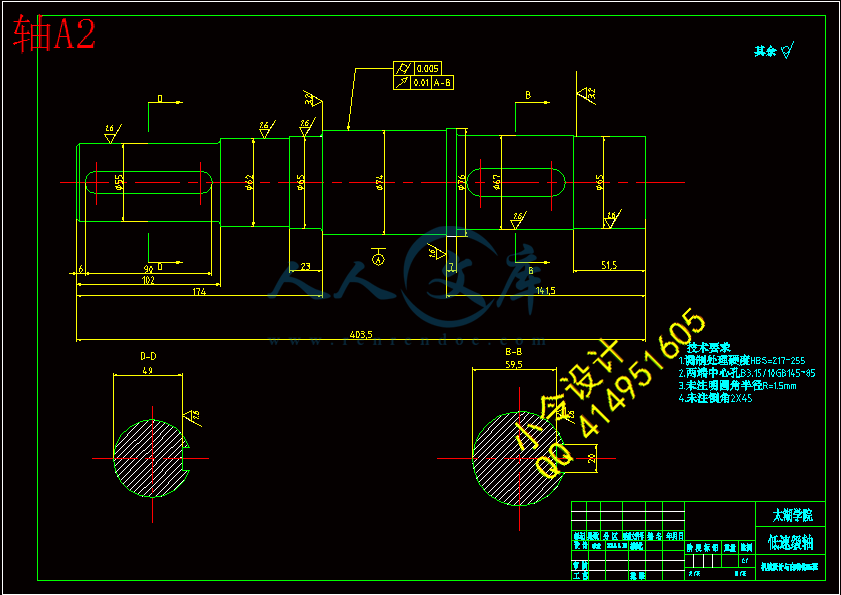
李欢的相关资料 2.doc

工业窑炉的设计(输送装置)【4张CAD图纸+毕业论文】【答辩通过】

收藏

压缩包内文档预览:(预览前20页/共24页)
预览图 预览图 预览图 预览图 预览图 预览图 预览图 预览图 预览图 预览图 预览图 预览图 预览图 预览图 预览图 预览图 预览图 预览图 预览图 预览图
编号:436935    类型:共享资源    大小:1.37MB    格式:RAR    上传时间:2015-05-29 上传人:好资料QQ****51605 IP属地:江苏
45
积分
关 键 词:
工业 设计 输送 装置
资源描述:

【温馨提示】 购买原稿文件请充值后自助下载。

[全部文件] 那张截图中的文件为本资料所有内容,下载后即可获得。


预览截图请勿抄袭,原稿文件完整清晰,无水印,可编辑。

有疑问可以咨询QQ:414951605或1304139763

摘  要

机械专业的毕业设计针对广大完成机械专业相关学科学习的应届毕业生,一次重要的事件性教学环节。同时也是高等工科院校大多数专业学生第一次较全面的设计能力训练,在此过程中,毕业生们将会对所学专业知识进行全面复习与实践。其目的是培养理论联系实际的设计思想,训练综合运用机械设计和相关选修课程的理论,结合实际分析和结局工程实际问题的能力,巩固、加深和扩展有关机械设计方面的知识。

此次设计的论文题目是《工业窑炉的设计(输送装置)》。选择输送装置方向的毕业设计题目完全符合本专业的要求,从应用性方面来说,输送装置又是很多机器所必不可少的一个部分。有效保证输送装置的功率及稳定性能够达到设计的要求,具有很好的发展前途和应用前景。带式输送机是胶带兼作牵引机构和承载机构的一种机械设备,因此本课题研究带式输送机的工作原理,以及整体机械中的零件尺寸计算、选用标准和强度校核,必须要求学生要有良好的心理素质和仔细认真的作风,对学生也是一次很好的练习机会。根据题目要求和机械设计的特点做了以下几方面的工作:①选择适宜的带式输送机的总体设计方案;②选择电动机并计算传动装置的运动和动力参数;③传动零件以及轴的设计计算,轴承、滚动轴承、键、联轴器的选择及校验计算;④绘制减速器装配图及典型零件图;⑤编写一份分析明晰,计算正确,阐述清晰的设计说明。


关键词:带式输送机;减速器 ;机械设计计算;校验计算


Abstract


Mechanical design course design is in complete mechanical design course, an important practical teaching link. Is higher engineering college students is the first time most comprehensive design ability training, but also of the mechanical course thoroughly review and practice. Its purpose is to develop the theory with the practice of design thought, training comprehensive use of mechanical design and relevant elective curriculum theory, combining with the production design analysis and the ability of solving engineering problems, consolidate, deepen and expand the mechanical design knowledge.

 This design topic is the design of industrial furnace(the conveying appliance).Choose the graduation design topic conveyor direction completely meet the professional requirements. From the application aspect, Conveying device is a part of the essential for many machine. Effectively guarantee the power and stability of conveying device can meet the design requirements, Having the good development prospect and application prospect. Belt conveyor is a kind of mechanical equipment tape used as traction mechanism and carrying mechanism, Therefore, the research of belt conveyor working principle,And the whole machinery parts size calculation, selection criteria and strength check,  Must require students to have a good psychological quality and carefully, The student is also a very good opportunity to practice. According to the topic request and mechanical design features the following aspects of work to do:①Select the general design scheme of belt conveyor is suitable for the design ;②Kinematic and dynamic parameters selection and calculation of the motor drive device ;③Calculation of transmission parts and shaft design, selection and check of bearing, rolling bearing, bond, coupling calculation; ④Rendering speed reducer assembly drawings and parts of typical figure ;⑤To prepare an analytical calculation is correct, clarity, clarity on the design description .


Key words: belt conveyer;  speed reducer;  Mechanical design ;  check computation


目  录

摘  要III

AbstractIV

目  录V

1 绪论1

 1.1 课题研究的背景和依据1

 1.2 本课题的研究意义1

 1.3 课题国内外研究现状及发展趋势1

  1.3.1 国外带式输送机技术的现状及趋势1

  1.3.2 国产带式输送机的发展现状及趋势1

2 带式输送机简介3

 2.1 带式输送机概述3

 2.2 带式输送机的特点3

 2.3 带式输送机安全运行保护装置3

3 输送装置的总体设计5

 3.1 原始数据及设计要求5

 3.2 传动方案分析5

  3.2.1 所选方案的优缺点5

 3.3 电动机的选择5

  3.3.1 选择电动机的功率5

  3.3.2 选择电动机的转速6

  3.3.3 选择电动机的类型6

 3.4 传动比的分配6

 3.5 传动装置的运动和动力参数分析7

4 传动件的设计计算9

 4.1 齿轮传动的设计计算9

  4.1.1 高速级齿轮的传动设计9

  4.1.2 低速级齿轮的传动设计12

5 轴系零部件设计16

 5.1 轴的设计和计算16

 5.2 滚动轴承的选择和计算20

  5.2.1 1轴上的轴承的选择和寿命计算20

  5.2.2 2轴上轴承的选择计算20

  5.2.3 3轴上轴承的选择计算21

 5.3 键连接的选择与计算22

 5.4 联轴器的选择与计算23

6 润滑与密封的说明24

 6.1 润滑说明24

 6.2 密封说明24

  6.2.1 减速器的密封24

  6.2.2 轴伸出端的密封24

  6.2.3 箱体结合面密封24

  6.2.4 轴承靠近箱体内外侧的密封24

7 拆装和调整的说明26

8 减速器箱体附件的说明28

9 结论和展望29

 9.1 结论29

 9.2 不足之处及未来展望29

致谢31

参考文献32


1 绪论

1.1  课题研究的背景和依据

带式输送机发展已逾百余年,随着科技和社会生产力的不断发展,带式输送机的设计由初期的主要用于农业作物等较小密度物料的输送,发展至用于制造、设计和安装的各种新技术、新方法的出现以及输送带接头技术的不断完善,带式输送机技术进入了一个高速发展阶段。它既可以进行散物料的输送,也可以进行成件物品的输送。除进行纯粹的物料输送外,还可以与各工业企业生产流程中的 工艺过程的要求相配合,形成有节奏的流水作业运输线。 带式输送机可以用于水平运 输或倾斜运输,使用非常方便,广泛应用于现代化的各种工业企业中,如:矿山的井下巷道、矿井地面运输系统、露天采矿场及选矿厂中。


1.2 本课题的研究意义

随着带式输送机在各行业的广泛应用,其结构简单、运行平稳、能耗低、对环境污染小、便于集中控制和实现自动化、管理维护方便、并可在连续装载条件下实现连续运输等许多优点,人们越发深刻理解和认识,因而带式输送机得到更多重视和高速发展。本设计在全面考虑多齿啮合、运转平稳等运动学和动力学的要求,实现高承载能力、高传递效率、高可靠性、优良动力学性能和送料定位准确等指标,而且要便于制造、装配和检修,设计了该具有合理结构的带式输送机。

此次毕业设计为设计一台工业窑炉的上下料输送机构。适用于产品340*340*30。要设计出结构,并且各个部件结构可以对应安装起来。生产率为80件/每分钟。要求运动平稳,送料定位准确。

1.3 课题国内外研究现状及发展趋势

 1.3.1 国外带式输送机技术的现状及趋势

国外带式输送机技术的发展很快,其主要表现在2个方面:一方面是带式输送机多元化功能、扩大应用范围化(高倾角带输送机、管状带式输送机、空间转弯带式输送等各种机型)方向发展;另一方面是带式输送机本身的硬件设备和技术有了很大提高,长距离、大运量、高带速等大型带式输送机成为重点发展,而将动态分析与监控技术用于带式输送机,从而使得运行性能和可靠性得到提升.

 1.3.2 国产带式输送机的发展现状及趋势

我国带式输送机行业起步相对国外较晚,但是在冶金、矿山、煤炭、交通、能源、建材等基础工业的带动下,我国带式输送机行业发展速度较快。近年来国产带式输送机产量逐年增长,根据中国重型机械工业协会数据显示,2009年我国带式输送机产量超过800万米。在产量逐年增长的同时,国产带式输送机产品的种类和技术水平也有了较大程度的提高。当前我国已经建成以北方重工、安徽盛运、山东矿机为代表的大型的带式输送机生产企业,并且随着国家产业结构的调整以及节能减排等政策的实施,行业内企业开始逐渐加大技术的研发力度,液压自动张紧技术、转弯技术、柔性制动技术、胶带防跑偏技术、监控技术以及变频技术在带式输送机上的逐步应用,使得带式输送机的安全可靠性得到了大幅度提高,同时,多转弯、上运、下运以及胶带翻转等关键技术都得到了很好地解决。当前,我国自主开发的带式输送机产品已经具备装备国内重大工程的能力,并已开始向海外市场进军。据资料显示,2009年,我国带式输送机出口产值约占带式输送机工业总产值的

15%-20%。

从未来国内市场的发展前景来看,煤炭、矿山开采、港口码头、电力、钢铁、粮食等行业的投资规模将继续扩大,这也必将带动带式输送机的市场需求不断增大;国际市场上,发展中国家正大力发展其本国的基础工业,如印度、巴西、东南亚、非洲、拉美等国家和地区对带式输送机的需求量也在逐渐增加。国产带式输送机由于的性价比较高,在国际市场上具有很强的竞争力。因此国内外市场的发展角度来看,国产带式输送机都具有较大的需求空间。根据市场的需求趋势,带式输送机将朝着长距离、大功率、大运量的方向发展,同时随着节能减排等政策的实施以及政府和全社会对安全生产的重视程度的增加,小规模火电、煤矿及水泥等生产企业相继关闭,取而代之的是具有先进工艺的大型企业,因此,对带式输送机的性能、质量、安全可靠性等方面的要求更高。由于带式输送机的核心部件决定了其整机的综合性能,因此带式输送机核心部件的专业化分工与协作将成为该行业发展的必然趋势,在带式输送机市场需求的带动下,其核心部件的市场价值也逐渐凸显。

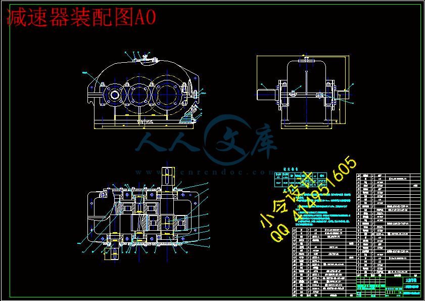
内容简介:
编号无锡太湖学院毕业设计(论文)相关资料题目: 工业窑炉的设计(输送装置) 信机 系 机械工程及自动化 专业学 号: 0923220学生姓名: 李 欢 指导教师: 徐伟明(职称: 教 授 ) (职称: )2013年5月25日目 录一、毕业设计(论文)开题报告二、毕业设计(论文)外文资料翻译及原文三、学生“毕业论文(论文)计划、进度、检查及落实表”四、实习鉴定表无锡太湖学院毕业设计(论文)开题报告题目: 工业窑炉的设计(输送装置) 信机系 机械工程及自动化 专业学 号: 0923220 学生姓名: 李 欢 指导教师: 徐伟明(职称: 教 授 ) (职称: )2012年11月20日课题来源本课题来源于导师布置的任务导老师科学依据(包括课题的科学意义;国内外研究概况、水平和发展趋势;应用前景等)输送装置的设计是机械工程及其自动化专业所包含的一个较为基础的内容,选择输送装置方向的毕业设计题目完全符合本专业的要求,从应用性方面来说,输送装置又是很多机器所必不可少的一个部分。有效保证输送装置的功率及稳定性能够达到设计的要求,具有很好的发展前途和应用前景。研究内容 1、 选择电动机,计算传动装置的运动和动力参数; 2、 拟定、分析传动装置的运动和动力参数;3、 进行传动件的设计计算,校核轴、轴承、联轴器、键等; 4、 绘制减速器装配图及典型零件图(图纸数达到3张或以上);5、 完成设计说明一份,分析明晰,计算正确,阐述清楚。适合的生产加工工 艺拟采取的研究方法、技术路线、实验方案及可行性分析首先确定整体设计方案,由公式的演算得到电动机的动力和运动分析,在以此推算相配的传动件,轴系零部件的尺寸规格。综上计算可以得到相关尺寸,再根据力学性能对所得零部件尺寸进行校验从而验证整体方案是否可行。研究计划及预期成果研究计划:2012年11月 布置任务。 2013年1月 对课题研究方向进行学习 2013年2月3月 拟定方案,提出专机总体方案,供讨论 2013年4月5日10日 确定方案,专机总体布置 11日20日 整机设计、部件设计 21日30日 改进并完成设计 2013年5月1日10日 撰写设计说明书 11日15日 总结预期成果:图纸、设计说明书特色或创新之处 带式输送机本身便具有价格便宜,标准化程度高特点,使成本大幅降低。高速级齿轮常布置在远离扭矩输入端的一边,以减小因弯曲变形所引起的载荷沿齿宽分布不均现象。已具备的条件和尚需解决的问题与指导老师的沟通中,对自己所做课题有了整体的认识,清晰了思路。指导老师提供了论文指导,从而使自己明确了每一步的方向。因第一次绘制复杂的装配图,所以在绘图方面还有待提高。指导教师意见同意作为本专业学生毕业设计课题,其难度和工作量均合适。 指导教师签名: 年 月 日教研室(学科组、研究所)意见 教研室主任签名: 年 月 日系意见 主管领导签名: 年 月 日英文原文Esign of Speed Belt ConveyorsG. Lodewijks, The Netherlands.This paper discusses aspects of high-speed belt conveyor design. The capacity of a belt conveyor is determined by the belt speed given a belt width and troughing angle. Belt speed selection however is limited by practical considerations, which are discussed in this paper. The belt speed also affects the performance of the conveyor belt, as for example its energy consumption and the stability of its running behavior. A method is discussed to evaluate the energy consumption of conveyor belts by using the loss factor of transport. With variation of the belt speed the safety factor requirements vary, which will affect the required belt strength. A new method to account for the effect of the belt speed on the safety factor is presented. Finally, the impact of the belt speed on component selection and on the design of transfer stations is discussed.Belt machine by conveyor belt continuous or intermittent motion to transport all kinds of different things ,Can transport all kinds of bulk materials, but also transport a variety of cardboard boxes, packaging bags, weight of single pieces of small goods, a wide range of uses . Belt conveyor belt material: rubber, silicone, PVC, PU and other materials, in addition to ordinary material conveying, but also to meet the transmission oil resistant, corrosion resistance, antistatic and other special requirements for material. Belt conveyor structure: groove belt machine, flat belt conveyor, climbing belt machine, turning machines and other forms belt, conveyor belt can also be created to enhance the tailgate, skirts and other accessories, can meet a variety of technological requirements.The belt conveyor drive: deceleration motor drive, electric drive roller.Belt conveyor mode: frequency control, stepless transmission.The belt rack material: carbon steel, stainless steel, aluminum profile.Scope of application: light industry, electronics, food, chemical, wood, etc.Belt machine equipment characteristics: belt conveyor is stable, the material and the conveyor belt there is no relative motion, to avoid damage to the carrier material. Low noise, suitable for quiet work environment requirements. Simple structure, easy maintenance. Low energy consumption, low use cost. Conveyor is a common dont have flexible traction component continuous conveying machinery, also called continuous conveyor.It is a material handling equipment, it with handling ability strong, persistent, direction, flexible, and other advantages in industrial production in large being applied. Although many types of belt conveyor, but its working principle is basic similar, most are driving draught device and drive transmission container transport materials. Conveyor can undertake level, the tilt and vertical conveyor, also can make the space transport routes, transmission lines is usually fixed, is a modern production and logistics transport indispensable important mechanical equipment. It has transmission capacity is strong, long distance transportation etc.With the development of industry, conveyor also obtained fast development, conveyor products have been also gradually improved. With the emergence of the power equipment of similar principle is applied, conveyor continuing into the 19th century, britons use basketwork, wire rope for traction belt conveyor. The principle of belt conveyor, when applied in the 17th century also recorded conveyor, in 1880 German company developed driven by steam belt conveyor. Then the British and German and launched inertial conveyor, if the conveyor belt, the application of the principle, creating a tilt of the belt conveyor, belt, traction with chains. All sorts of conveyor during this time arise conveyor, based on human, hydraulic power drive such. All the structures conveyor successively appeared. In 1887 americans produced the screw conveyor, make enterprise internal, between enterprise and inter-city transportation possible. The development history of belt conveyor, they very ancient instead of the original motive for conveyor provide driving force. Ancient people began to use water overturned and high TongChe conveyor, in turn after the water conservancy projects belt conveyor begin in power. Quick-tempered exaltsAccording to the mode of operation conveying machinery can be divided into: 1: belt conveyor 2: screw conveyor 3: dou pattern lift machineThe future of large scale, will toward belt use scope, energy consumption, low pollution less, material automatically grading, etc.Past research has shown the economical feasibility of using narrower, faster running conveyor belts versus wider, slower running belts for long overland belt conveyor systems. See for example I-5. Today, conveyor belts running at speeds around 8 m/s are no exceptions. However, velocities over 10 m/s up to 20 m/s are technically (dynamically) feasible and may also be economically feasible. In this paper belt speeds between the 10 and 20 m/s are classified as high. Belt speeds below the 10 m/s are classified as low.Using high belt speeds should never be a goal in itself. If using high belt speeds is not economically beneficial or if a safe and reliable operation is not ensured at a high belt speed then a lower belt speed should be selected.Selection of the belt speed is part of the total design process. The optimum belt conveyor design is determined by static or steady state design methods. In these methods the belt is assumed to be a rigid, inelastic body. This enables quantification of the steady-state operation of the belt conveyor and determination of the size of conveyor components. The specification of the steady-state operation includes a quantification of the steady-state running belt tensions and power consumption for all material loading and relevant ambient conditions. It should be realized that finding the optimum design is not a one-time effort but an iterative process 6.Design fine-tuning, determination of the optimum starting and stopping procedures, including determination of the required control algorithms, and determination of the settings and sizes of conveyor components such as drives, brakes and flywheels, are determined by dynamic design methods. In these design methods, also referred to as dynamic analyses, the belt is assumed to be a three-dimensional (visco-) elastic body. A three dimensional wave theory should be used to study time dependent transmission of large local force and displacement disturbances along the belt 7. In this theory the belt is divided into a series of finite elements. The finite elements incorporate (visco-) elastic springs and masses. The constitutive characteristics of the finite elements must represent the rheological characteristics of the belt. Dynamic analysis produces the belt tension and power consumption during non-stationary operation, like starting and stopping, of the belt conveyor.This paper discusses the design of high belt-speed conveyors, in particular the impact of using high belt speeds on the performance of the conveyor belt in terms of energy consumption and safety factor requirements. Using high belt speeds also requires high reliability of conveyor components such as idlers to achieve an acceptable component life. Another important aspect of high-speed belt conveyor design is the design of efficient feeding and discharge arrangements. These aspects will be discussed briefly.Many methods of analyzing a belts physical behavior as a rheological spring have been studied and various techniques have been used. An appropriate model needs to address: 1. Elastic modulus of the belt longitudinal tensile member 2. Resistances to motion which are velocity dependent (i.e. idlers) 3. Viscoelastic losses due to rubber-idler indentation 4. Apparent belt modulus changes due to belt sag between idlers Since the mathematics necessary to solve these dynamic problems are very complex, it is not the goal of this presentation to detail the theoretical basis of dynamic analysis. Rather, the purpose is to stress that as belt lengths increase and as horizontal curves and distributed power becomes more common, the importance of dynamic analysis taking belt elasticity into account is vital to properly develop control algorithms during both stopping and starting. Using the 8.5 km conveyor in Figure 23 as an example, two simulations of starting were performed to compare control algorithms. With a 2x1000 kW drive installed at the head end, a 2x1000 kW drive at a midpoint carry side location and a 1x1000kW drive at the tail, extreme care must be taken to insure proper coordination of all drives is maintained. Figure 27 illustrates a 90 second start with very poor coordination and severe oscillations in torque with corresponding oscillations in velocity and belt tensions. The T1/T2 slip ratio indicates drive slip could occur. Figure 28 shows the corresponding charts from a relatively good 180 second start coordinated to safely and smoothly accelerate the conveyor. Figure 27-120 Sec Poor Start BELTSPEED BELT SPEED SELECTIONThe lowest overall belt conveyor cost occur in the range of belt widths of 0.6 to 1.0 m 2. The required conveying capacity can be reached by selection of a belt width in this range and selecting whatever belt speed is required to achieve the required flow rate. Figure 1 shows an example of combinations of belt speed and belt width to achieve Specific conveyor capacities. In this example it is assumed that the bulk density is 850 kg/m3 (coal) and that the trough angle and the surcharge angle are 35 and 20 respectively.Figure 1: Belt width versus belt speed for different capacities.Belt speed selection is however limited by practical considerations. A first aspect is the troughability of the belt. In Figure 1 there is no relation with the required belt strength (rating), which partly depends on the conveyor length and elevation. The combination of belt width and strength must be chosen such that good troughability of the belt is ensured. If the troughability is not sufficient then the belt will not track properly. This will result in unstable running behavior of the belt, in particular at high belt speeds, which is not acceptable. Normally, belt manufacturers expect a sufficiently straight run if approximately 40% of the belt width when running empty, makes contact with the carrying idlers. Approximately 10% should make tangential contact with the center idler roll.A second aspect is the speed of the air relative to the speed of the bulk solid material on the belt (relative airspeed). If the relative airspeed exceeds certain limits then dust will develop. This is in particular a potential problem in mine shafts where a downward airflow is maintained for ventilation purposes. The limit in relative airspeed depends on ambient conditions and bulk material characteristics.A third aspect is the noise generated by the belt conveyor system. Noise levels generally increase with increasing belt speed. In residential areas noise levels are restricted to for example 65 dB. Although noise levels are greatly affected by the design of the conveyor support structure and conveyor covers, this may be a limiting factor in selecting the belt speed.BELT SPEED VARIATIONThe energy consumption of belt conveyor systems varies with variation of the belt speed, as will be shown in Section 3. The belt velocity can be adjusted with bulk material flow supplied at the loading point to save energy. If the belt is operating at full tonnage then it should run at the high (design) belt speed. The belt speed can be adjusted (decreased) to the actual material (volume) flow supplied at the loading point. This will maintain a constant filling of the belt trough and a constant bulk material load on the belt. A constant filling of the belt trough yields an optimum loading-ratio, and lower energy consumption per unit of conveyed material may be expected. The reduction in energy consumption will be at least 10% for systems where the belt speed is varied compared to systems where the belt speed is kept constant 8.Varying the belt speed with supplied bulk material flow has the following advantages:Less belt wear at the loading areasLower noise emissionImproved operating behavior as a result of better belt alignment and the avoidance of belt lifting in concave curve by reducing belt tensionsDrawbacks include: Investment cost for controllability of the drive and brake systemsVariation of discharge parabola with belt speed variationControl system required for controlling individual conveyors in a conveyor systemConstant high belt pre-tensionConstant high bulk material load on the idler rollsAn analysis should be made of the expected energy savings to determine whether it is worth the effort of installing a more expensive, more complex conveyor system.ENERGY CONSUMPTIONClients may request a specification of the energy consumption of a conveyor system, for example quantified in terms of maximum kW-hr/ton/km, to transport the bulk solid material at the design specifications over the projected route. For long overland systems, the energy consumption is mainly determined by the work done to overcome the indentation rolling resistance 9. This is the resistance that the belt experiences due to the visco-elastic (time delayed) response of the rubber belt cover to the indentation of the idler roll. For in-plant belt conveyors, work done to overcome side resistances that occur mainly in the loading area also affects the energy consumption. Side resistances include the resistance due to friction on the side walls of the chute and resistance that occurs due to acceleration of the material at the loading point.The required drive power of a belt conveyor is determined by the sum of the total frictional resistances and the total material lift. The frictional resistances include hysteresis losses, which can be considered as viscous (velocity dependent) friction components. It does not suffice to look just at the maximum required drive power to evaluate whether or not the energy consumption of a conveyor system is reasonable. The best method to compare the energy consumption of different transport systems is to compare their transport efficiencies.TRANSPORT EFFICIENCYThere are a number of methods to compare transport efficiencies. The first and most widely applied method is to compare equivalent friction factors such as the DIN f factor. An advantage of using an equivalent friction factor is that it can also be determined for an empty belt. A drawback of using an equivalent friction factor is that it is not a pure efficiency number. It takes into account the mass of the belt, reduced mass of the rollers and the mass of the transported material. In a pure efficiency number, only the mass of the transported material is taken into account.The second method is to compare transportation cost, either in kW-hr/ton/km or in $/ton/km. The advantage of using the transportation cost is that this number is widely used for management purposes. The disadvantage of using the transportation cost is that it does not directly reflect the efficiency of a system.The third and most pure method is to compare the loss factor of transport 10. The loss factor of transport is the ratio between the drive power required to overcome frictional losses (neglecting drive efficiency and power loss/gain required to raise/lower the bulk material) and the transport work. The transport work is defined as the multiplication of the total transported quantity of bulk material and the average transport velocity. The advantage of using loss factors of transport is that they can be compared to loss factors of transport of other means of transport, like trucks and trains. The disadvantage is that the loss factor of transport depends on the transported quantity of material, which implies that it can not be determined for an empty belt conveyor.The following are loss factors of transport for a number of transport systems to illustrate the concept:Continuous transport: Slurry transport around 0.01 Belt conveyors between 0.01 and 0.1 Vibratory feeders between 0.1 and 1 Pneumatic conveyors around 1 0 Discontinuous transport: Ship between 0.001 and 0.01 Train around 0.01 Truck between 0.05 and 0.1 INDENTATION ROLLING RESISTANCEFor long overland systems, the energy consumption is mainly determined by the work done to overcome the indentation rolling resistance. Idler rolls are made of a relatively hard material like steel or aluminum whereas conveyor belt covers are made of much softer materials like rubber or PVC. The rolls therefore indent the belts bottom-cover when the belt moves over the idler rolls, due to the weight of the belt and bulk material on the belt. The recovery of the compressed parts of the belts bottom cover will take some time due to its visco-elastic (time dependent) properties. The time delay in the recovery of the belts bottom cover results in an asymmetrical stress distribution between the belt and the rolls, see Figure 2. This yields a resultant resistance force called the indentation rolling resistance force. The magnitude of this force depends on the visco-elastic properties of the cover material, the radius of the idler roll, the vertical force due to the weight of the belt and the bulk solid material, and the radius of curvature of the belt in curves in the vertical plane.Figure 2: Asymmetric stress distribution between belt and roll 7.It is important to know how the indentation rolling resistance depends on the belt velocity to enable selection of a proper belt velocity, 11.Figure 3: Loss factor (tanb) of typical cover rubber 7Firstly, the indentation rolling resistance depends on the vertical load on the belt, which is the sum of the belt and the bulk material weight. If the vertical load on the belt decreases with a factor 2 then the indentation rolling resistance decreases with a factor 2.52 (2 4/3). The bulk load decreases with increasing belt speed assuming a constant capacity. Therefore, the indentation rolling resistance decreases more than proportionally with increasing belt speed.Secondly, the indentation rolling resistance depends on the size of the idler rolls. If the roll diameter increases with a factor 2 then the indentation rolling resistance decreases with a factor 1.58 (2 2/3). In general the idler roll diameter increases with increasing belt speed to limit the bearing rpms to maintain acceptable idler life. In that case the indentation rolling resistance decreases with increasing belt speed.Thirdly, the indentation rolling resistance depends on the visco-elastic properties of the belts cover material. These properties depend on the deformation rate, see Figure 3. The deformation rate in its turn depends on the size of the deformation area in the belts bottom cover (depending on belt and bulk load) and on the belt speed. In general the indentation rolling resistance increases with increasing deformation rate (and thus belt speed), but only to a relatively small account.Fourthly, the indentation rolling resistance depends on the belts bottom cover thickness. If the bottom cover thickness increases with a factor 2 then the indentation rolling resistance increases with a factor 1.26 (2 1/3). if a bottom cover is increased to account for an increase in belt wear with increasing belt speed, then the indentation rolling resistance increases as well.It should be realized that the indentation rolling resistance, although important, is not the only velocity dependent resistance. The rolling resistance of the idler rolls for example depends on the vertical load as well as on their rotational speed. The effect of the vertical load, which directly depends on the belt speed, is large. The effect of the rotational speed is much smaller. Another resistance occurs due to acceleration of the bulk solid material at the loading point. This resistance increases quadratically with an increase in belt speed assuming that the bulk material falls straight onto the belt. This will affect smaller, in plant belt conveyors in particular.EXAMPLETo illustrate the concept discussed above lets consider a 6 km long conveyor belt with a capacity of 5000 TPH. The trough angle, the surcharge angle and the bulk density are again taken 35, 20 and 850 kg/m3 respectively. Figure 4 shows the required belt speed as a function of the belt width to achieve the required capacity of 5000 TPH. This figure is somewhat similar to Figure 1.Figure 4The figures 5 and 6 show the required belt strength and the required drive power as a function of the belt speed. The required belt strength decreases and the required drive power slowly increases with increasing belt speed as can be seen in those figures. Figure 7 shows the loss factor of transport and the DIN f factor versus belt speed. The loss factor of transport is always higher than the DIN f factor because the DIN f factor takes the mass of the belt into account (in the denominator) whereas the loss factor of transport only accounts for the mass of the bulk solid material. Intuitively, it may be expected that there will be an economically optimum belt speed in the high belt speed range. The determination of the optimum belt speed however, requires more information and is beyond the scope of this paper.Belt conveyor safety operation procedures 1、Fixed conveyor should be required for the installation method to install on a regular basis.Mobile conveyor wheels should be before the official run using triangular wedge or with a brake check. In order to avoid the occurrence of walking, there are multiple conveyor parallel work.Between machine and machine, a proper channel between the machine and the wall. 2、To check the operation of conveyor, belt buckle, and the part of bearing device is normal before use, protective equipment are complete. Belt tension must be adjusted to the appropriate level before starting . 3、The belt conveyor unloaded start. Normal operation before feeding. Prohibit driving after feeding 4、Several conveyor series operation, from the discharge end, sequence starting. All the normal operation, in order to feed 5、Belt deviation phenomenon occurs during the operation, should stop adjustment, not reluctantly, to avoid edge wear and increase the load 6, work environment and sent the material temperature not higher than 50 and below -10 .7, the conveyor belt against pedestrian or riding on. 8、Conveyor motor must be well insulated. Mobile conveyor cable dont pull and drag. The motor is to be reliable grounding. 9、when the belt slipping is strictly prohibited to use hand to pull the belt, so as to avoid the occurrence of accidents.Misalignment fault belt line and the solutions Conveyor belt running deviation of the belt is the most common faults.n order to solve the fault point is to pay attention to the installation size precision and daily maintenance. Deviation of a variety of reasons,Need different treatment according to different reasons: 1, adjust the carrying idlers. 2, install self-aligning roller group. 3, adjust the drive drum and drum to position. 4, tensioning the adjustment at. 中文译文带式输送机G. Lodewijks,荷兰 本文主要探讨高速带式输送机设计方面的问题。带式输送机的输送量取决于输送带的速度、传送带宽度和托辊槽形角。 然而输送带速度的选择又受到各种实际条件的限制,在本文有这方面的讨论。 输送带速度也影响传送带的性能,例如它的能源消耗和它连续运行的稳定性。 一种计算输送带的能源消耗的方法就是通过考虑运输过程中的各种能量损耗来进行估算的。 输送带速度的不同使得安全系数的要求也各不相同,这也影响输送带所要求的强度。一种新的计算输送带速度对安全系数的影响的方法在本文中被介绍。 最后,输送带速度的冲击对各组成部分的选择和对中转站设计的影响也在本文中被讨论。 皮带机是皮带输送机的简称,皮带机运用输送带的连续或间歇运动来输送各种轻重不同的物品,既可输送各种散料,也可输送各种纸箱、包装袋等单件重量不大的件货,用途广泛。皮带机输送带的材质有:橡胶、硅胶、PVC、PU等多种材质,除用于普通物料的输送外,还可满足耐油、耐腐蚀、防静电等有特殊要求物料的输送。皮带机结构形式有:槽型皮带机、平型皮带机、爬坡皮带机、转弯皮带机等多种形式,输送带上还可增设提升挡板、裙边等附件,能满足各种工艺要求。皮带机驱动方式有:减速电机驱动、电动滚筒驱动。皮带机调速方式有:变频调速、无极变速。皮带机架材质有:碳钢、不锈钢、铝型材。应用范围:轻工,电子,食品,化工,木业,机械等行业。皮带机设 备 特点:皮带机输送平稳,物料与输送带没有相对运动,能够避免对输送物的损坏。噪音较小,适合于工作环境要求比较安静的场合。结构简单,便于维护。能耗较小,使用成本低。输送机是一种常用的不具有挠性牵引构件的连续物料搬运机械,又称连续输送机。是一种物料搬运装备,它以搬运能力强、持续性好、方向灵活等优点,在工业生产中大量被应用。输送机的种类虽然很多,但是其工作原理却基本相似,多数都是以动力驱动牵引装置,带动输送容器运输物料。输送机可进行水平、倾斜和垂直输送,也可组成空间输送线路,输送线路一般是固定的,是现代化生产和物流运输不可或缺的重要机械设备。它有输送能力强,运输距离长等优点。输送机械按运作方式可以分为:1:带式输送机 2:螺旋输送机 3:斗式提升机未来输送机的将向着大型化、使用范围广、能量消耗低、污染较少、物料自动分拣等方面发展。过去的研究已经证实使用窄带输送机的经济可行性,输送带的速度变快要求输送带的宽度随之变宽,低速输送机适于长距离输送。 例如图1 - 5。 现在,传送带以8 m/s的速度运行是没有问题的。 无论怎样,输送带速度在10m/s到20 m/s在技术上是(动态地)可行的,并且也许在经济上也是可行的。本文将输送带速度在10和20 m/s之间的定义为高速。输送带速度在10m/s之下的定义为低速。使用高速输送带的目的并不在于它本身。 如果使用高速输送带不是经济上有利,或则,如果安全和可靠的操作没有保证的,那么就应该选择低速输送带。输送带速度的选择是总的设计过程的一部分。 静态或稳定的设计方法决定了带式输送机的优化设计。 在这些设计方法中输送带被认为是刚性的,静止的。 这增加了输送机稳定运行的质量和也决定了带式输送机各零部件的尺寸。 稳定操作包括传送带稳定运行时的张力、相对各种物料载荷的能量消耗和相关的工作环境情况。 应该体会到找到最优的设计不是一次性的努力,而是一个反复的过程6。优化设计,开始于优化的决心,终于符合要求的确定的控制算法和组成输送机的各零部件确定的位置和尺寸的大小,例如驱动,闸和飞轮,可由动态设计方法确定。 在这些设计方法中,也涉及动态分析,输送带可看作是一个三维的弹性体。三维波动理论被用来研究大的局部受力传输的时间和沿输送带的干扰传输的位移7。 在这种理论中,输送带被划分成一系列的有限元。 有限元一体化为有弹性的弹簧和块。 有限元素的结构性特征能代表输送带的流变特征。 动态分析产生在动态操作时输送带产生的张力和能量消耗,例如在带式输送机启动和制动时。本文主要讨论告诉输送机的设计,特别是使用高速输送带对输送带在能源消耗和安全系数要求方面的影响。 使用高速输送带也要求输送机的各零部件有高可靠性,例如托辊组应达到所要求的使用寿命。 高速带式输送机设计的另一个重要方面是高效率的装料和卸载的合理安排。 这些方面在本文中将被简单地讨论。许多分析输送带无力性能的方法都在研究,如把它看做一个流变弹簧,而且大量的技术也被用来这方面的研究。一个合适的模型需要包含以下几个方面: 1. 传送带纵向拉伸量的弹性模数2. 对从属运动的阻抗3. 凹陷处的粘弹性损失4. 由于输送带的下垂引起的输送带模数变动因为纯数学解决这些动态问题是非常复杂的,它的目标不是详述基础的动态理论分析。相反,它的目的是让长距离输送、水平弯曲、分散驱动在输送机上更普遍,对传送带停止和开始进行弹性动态分析的重要性是开发适当的控制算法。 以图23 8.5千米输送机为例,两个虚拟开始被模拟来比较它们的控制算法。一种是两个1000千瓦的驱动安装在头部尾端,二个1000千瓦驱动安装在输送面的中点,另一个1000千瓦驱动安装在尾部,要极端小心保证所有驱动的协调与维护。 图27显示一个不协调并严重摆动输送机120秒启动的扭矩图及其相应的速度输送带摆动图。T1/T2滑动比率表明推进滑动可能发生。图28显示对应的一个180秒启动图,并能够安全和顺利的加速输送机。 图27-120 秒恶劣启动 续使用多年。但是受到原来机械结构的限制,不宜做突破性的改造。带速 传送带速度选择整体皮带输送机的最低成本在传送带宽度0.6到1.0 m的系列范围内2。 所要求的输送量可以在这个传送带宽度范围中选择和也可以选择符合输送量要求的任何必要的输送带速度。 图1例子显示了传送带速度和传送带宽度的组合所达到的具体输送机的输送量。 在本例中假设,物料的容积密度是850 kg/m3 (煤炭),并且槽形托辊的槽角和附加角分别为35 和20 。图1 :各种输送带的宽度相对不同的输送量的熟送带的速度然而传送带速度选择又被实际工作环境限制。 第一个方面是传送带的可成槽性,在图1没有给出与输送带强度(规定值)的联系,这部分取决于输送机的长度和海拔。 为使送带的可成槽性被保证必须选择传送带宽度和强度。 如果输送带没有充足的可成槽性就不会有适当地运行轨迹。 这导致传送带连续运行的不稳定,特别是高速传送带,这是不允许的。 通常,传送带制造者期待输送机空载时,40%传送带宽度上进行着直线运行,并且与承载托辊的正常接触。第二方面是空气在传送带上相对疏松固体物料的速度(空气相对速度)。 如果相对空速超出某些极限后灰尘将产生重要影响。 这特别是对矿井产生了潜在问题影响,因为矿井为了通气存在向下气流。空速的相对极限取决于四周情况和粒状材料特征。第三个方面是带式输送机系统引起的噪声。 随着传送带速度的增加,噪声级别也通常增加。 在住宅区噪声级限于65dB。 虽然噪声级受输送机的支持结构和输送机的覆盖层的设计的影响很大,这也是选择输送带速度的一个限制因素。 输送带速度变化带式输送机系统的能量消耗随传送带速度的变化而变化,这将在第3部分中论述。 为了节省能量,传送带速度应调整与供料点的粒状物料特性匹配。 如果传送带正在满载运行,那么它应该运行在高(设计)速度。 传送带速度可以在物质(容量)输入点进行调整。 这将维持传送带在带槽内的连续装填和在传送带的连续的粒状材料的装载。 传送带带槽在恒定的装填时产生一个最优的装货比率,并且每个输送物料单元被期望消耗能源量最低。 比较各种传送带速度不同的输送机能源消耗相差将近10% 8
温馨提示:
1: 本站所有资源如无特殊说明,都需要本地电脑安装OFFICE2007和PDF阅读器。图纸软件为CAD,CAXA,PROE,UG,SolidWorks等.压缩文件请下载最新的WinRAR软件解压。
2: 本站的文档不包含任何第三方提供的附件图纸等,如果需要附件,请联系上传者。文件的所有权益归上传用户所有。
3.本站RAR压缩包中若带图纸,网页内容里面会有图纸预览,若没有图纸预览就没有图纸。
4. 未经权益所有人同意不得将文件中的内容挪作商业或盈利用途。
5. 人人文库网仅提供信息存储空间,仅对用户上传内容的表现方式做保护处理,对用户上传分享的文档内容本身不做任何修改或编辑,并不能对任何下载内容负责。
6. 下载文件中如有侵权或不适当内容,请与我们联系,我们立即纠正。
7. 本站不保证下载资源的准确性、安全性和完整性, 同时也不承担用户因使用这些下载资源对自己和他人造成任何形式的伤害或损失。
提示  人人文库网所有资源均是用户自行上传分享,仅供网友学习交流,未经上传用户书面授权,请勿作他用。
关于本文
本文标题:工业窑炉的设计(输送装置)【4张CAD图纸+毕业论文】【答辩通过】
链接地址:https://www.renrendoc.com/p-436935.html

官方联系方式

2:不支持迅雷下载,请使用浏览器下载   
3:不支持QQ浏览器下载,请用其他浏览器   
4:下载后的文档和图纸-无水印   
5:文档经过压缩,下载后原文更清晰   
关于我们 - 网站声明 - 网站地图 - 资源地图 - 友情链接 - 网站客服 - 联系我们

网站客服QQ:2881952447     

copyright@ 2020-2025  renrendoc.com 人人文库版权所有   联系电话:400-852-1180

备案号:蜀ICP备2022000484号-2       经营许可证: 川B2-20220663       公网安备川公网安备: 51019002004831号

本站为文档C2C交易模式,即用户上传的文档直接被用户下载,本站只是中间服务平台,本站所有文档下载所得的收益归上传人(含作者)所有。人人文库网仅提供信息存储空间,仅对用户上传内容的表现方式做保护处理,对上载内容本身不做任何修改或编辑。若文档所含内容侵犯了您的版权或隐私,请立即通知人人文库网,我们立即给予删除!