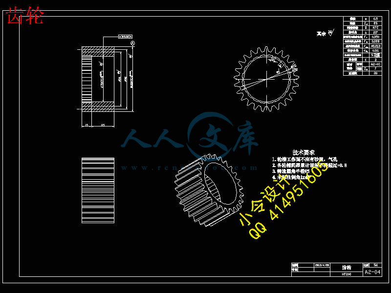
齿轮.DWG
齿轮.DWG

汽车自动调整臂的三维结构及预装配设计【9张CAD图纸+毕业论文】【答辩通过】

收藏

压缩包内文档预览:
预览图
编号:437219    类型:共享资源    大小:4.80MB    格式:RAR    上传时间:2015-05-30 上传人:好资料QQ****51605 IP属地:江苏
50
积分
关 键 词:
汽车 自动 调整 调剂 三维 结构 预装 设计
资源描述:

【温馨提示】 购买原稿文件请充值后自助下载。

[全部文件] 那张截图中的文件为本资料所有内容,下载后即可获得。


预览截图请勿抄袭,原稿文件完整清晰,无水印,可编辑。

有疑问可以咨询QQ:414951605或1304139763

摘  要

汽车自动调整臂(简称调整臂——ASA)是汽车制动系统的必备结构之一。传统的汽车自动调整臂结构复杂使用者不便操作。而本次设计的自动调整臂在结构上做了相应的调整,使得结构相对简单,而且安装高度可调,更便于安装。

本结构是应用在汽车制动系统上,利用齿条和齿轮的单向可传动控制蜗轮转动以控制凸轮轴的旋转角度。主要零部件有:蜗轮蜗杆配合,齿条齿轮配合,以及单向离合结构。通过其配合来实现对凸轮轴的调整,使得制动间隙保持在恒定最优间隙。

本文对制动调整臂的开发原理,具体特点和使用方法做了相应介绍。


关键词:自动调整臂;结构;原理


3D design and pre-assembled design of the car automatically adjusts the arm

Abstract

Car adjustment arm (referred to as the adjustment arm - ASA) is one of the essential structure of the automotive braking systems. The traditional automotive automatically adjust the arm structure complex user inconvenience. The design of the automatic adjustment arm to do the appropriate adjustments in the structure, the structure is relatively simple, and the installation height adjustable, easy to install.

The present structure is applied to the vehicle brake system, the unidirectional transmission control a worm wheel rotational angle of rotation of the camshaft to control the use of a rack and pinion. The main components are: worm with rack and pinion with one-way clutch structure. With the camshaft adjustment, so that the brake clearance is maintained at a constant optimum gap.

Corresponding development principles, specific characteristics and use of the brake adjustment arm.


Key Words: Automatic Slack Adjuster; Structure;Principle

目  录

1 绪论1

1.1 开发背景1

1.2 结构设计的意义4

1.3 开发者的主要工作5

1.4 论文的组织结构6

2 相关技术介绍7

2.1 自动调整臂介绍7

2.1.1自动调整臂简介7

2.1.2自动调整臂特点7

2.1.3自动调整臂的结构8

2.2 自动调整臂工作原理介绍8

3 自动调整臂的设计和实现9

3.1 自动调整臂设计10

3.1.1 自动调整臂设计任务10

3.1.2 蜗轮蜗杆配合10

3.1.3 齿轮齿条配合15

3.1.3 单向离合器结构设计18

3.1.4 臂体设计19

3.2 自动调整臂装配20

3.2.1 调整臂内部结构装配20

3.2.2 调整臂总体结构装配图21

3.3 调整臂的安装21

3.3.1 基本传动说明21

3.3.2 自动调整臂安装说明25

4 校核28

4.1 校核计划及执行情况28

4.2 核心零件校核28

4.2.1 单向离合器弹簧校核28

4.2.2 轴承校核29

4.2.3 蜗杆设计校核29

5 建模31

6 结论33

7 体会34

参考文献35

致  谢36

毕业设计(论文)知识产权声明37

毕业设计(论文)独创性声明38


1 绪论

1.1开发背景

21世纪以来,随着公路建设的飞速发展,随着汽车加工制造业的发展,汽车已经成为一项普遍的代步工具,使得公路客运飞速发展。据统计,本世纪以来由于交通事故所造成的人员伤亡数量堪比二战期间的人员伤亡数量。这使得人们不得不重视汽车的制动系统,特别是高速客车的制动可靠性和安全性。因此,各种自动装置和电子装置应运而生。在制动系统,除了安装ABS保证车辆的安全性外,保持制动鼓(制动盘)与摩擦片(摩擦衬块)之间的间隙恒定对保证制动可靠性非常重要。因为汽车在使用过程中,由于制动器摩擦片的磨损会使制动鼓(制动盘)与摩擦衬片(摩擦衬块)之间的间隙增大,若不及时调整,会使气室推杆行程过大、制动效能降低。另外,鼓式制动器有时摩擦接触面正处在最佳状态,如果此时拆下检查调整,可能破坏原来完好的配合,反而使制动效能降低。因此,对制动系统这样的安全系统不应过分依赖于保养调整,而在设计阶段就应使其具有较高的可靠性水平和自动调整能力。

制动系统是汽车上用以使外界(主要是路面)在汽车某些部分(主要是车轮)施加一定的力,从而对其进行一定程度的强制制动的一系列专门装置。制动系统作用是:使行驶中的汽车按照驾驶员的要求进行强制减速甚至停车;使已停驶的汽车在各种道路条件下(包括在坡道上)稳定驻车;使下坡行驶的汽车速度保持稳定。对汽车起制动作用的只能是作用在汽车上且方向与汽车行驶方向相反的外力,而这些外力的大小都是随机的、不可控制的,因此汽车上必须装设一系列专门装置以实现上述功能。

 a. 一般制动系的基本结构

 (1) 主要由车轮制动器和液压传动、气压传动机构组成;

 (2) 车轮制动器主要由旋转部分、固定部分和调整机构组成,旋转部分是制动鼓;  

 (3) 固定部分包括制动蹄和制动底板;调整机构由偏心支承销和调整凸轮组成用于调整蹄鼓间隙;

 (4) 液压制动传动机构主要由制动踏板、推杆、制动主缸、制动轮缸和管路组成;

 (5) 气压制动传动机构主要由制动踏板、推杆、制动总阀、空气干燥器、四回;

 (6) 路保护阀、制动气室和管路等组成。

 b. 制动工作原理 制动系统的一般工作原理是,利用与车身(或车架)相连的非旋转元件和与车轮(或传动轴)相连的旋转元件之间的相互摩擦来阻止车轮的转动或转动的趋势。

 (1) 制动系不工作时 蹄鼓间有间隙,车轮和制动鼓可自由旋转。

 (2) 制动时 要汽车减速,脚踏下制动器踏板通过推杆和主缸活塞,使主缸油液在一定压力下流入轮缸,并通过两轮缸活塞推使制动蹄绕支承销转动,上端向两边分开而以其摩擦片压紧在制动鼓的内圆面上。不转的制动蹄对旋转制动鼓产生摩擦力矩,从而产生制动力。

 (3) 解除制动 当放开制动踏板时回位弹簧即将制动蹄拉回原位,制动力消失。

 c. 制动主缸的结构及工作过程 制动主缸的作用是将自外界输入的机械能转换成液压能,从而液压能通过管路再输给制动轮缸

制动主缸分单腔和双腔式两种,分别用于单、双回路液压制动系。

 (1) 单腔式制动主缸

  1) 制动系不工作时 不制动时,主缸活塞位于补偿孔、回油孔之间

  2) 制动时 活塞左移,油压升高,进而车轮制动

  3) 解除制动 撤除踏板力,回位弹簧作用,活塞回位,油液回流,制动解除

 (2) 双腔式制动主缸

  1) 结构 (如一汽奥迪100型轿车双回路液压制动系统中的串联式双腔制动主缸)

主缸有两腔

第一腔与右前、左后制动器相连;第二腔与左前、右后制动器相通

每套管路和工作腔又分别通过补偿孔和回油孔与储油罐相通。第二活塞由右端弹簧保持在正确的初始位置,使补偿孔和进油孔与缸内相通。第一活塞在左端弹簧作用下,压靠在套上,使其处于补偿孔和回油孔之间的位置。

  2) 工作原理 制动时,第一活塞左移,油压升高,克服弹力将制动液送入右前左后制动回路;同时又推动第二活塞,使第二腔液压升高,进而两轮制动

解除制动时,活塞在弹簧作用下回位,液压油自轮缸和管路中流回制动主缸。如活塞回位迅速,工作腔内容积也迅速扩大,使油压迅速降低。储液罐里的油液可经进油孔和活塞上面的小孔推开密封圈流入工作腔。当活塞完全回位时,补偿孔打开,工作腔内多余的油由补偿孔流回储液罐。若液压系统由于漏油,以及由于温度变化引起主缸工作腔、管路、轮缸中油液的膨胀或收缩,都可以通过补偿孔进行调节。

制动轮缸的功用是将液力转变为机械推力。有单活塞和双活塞两种。奥迪100的双活塞式轮缸体内有两活塞,两皮碗,弹簧使皮碗、活塞、制动蹄紧密接触。 制动时,液压油进入两活塞间油腔,进而推动制动蹄张开,实现制动。轮缸缸体上有放气螺栓,以保证制动灵敏可靠。

为了保证汽车行使安全,发挥高速行使的能力,制动系必须满足下列要求

制动效能好。评价汽车制动效能的指标有:制动距离、制动减速度、制动时间;操纵轻便,制动时的方向稳定性好。制动时,前后车轮制动力分配合理,左右车轮上的制动力应基本相等,以免汽车制动时发生跑偏和侧滑;制动平顺性好。制动时应柔和、平稳;解除时应迅速、彻底;散热性好,调整方便。这要求制动蹄摩擦片抗高温能力强,潮湿后恢复能力快,磨损后间隙能够调整,并能够防尘、防油;带挂车时,能使挂车先于主车产生制动,后于主车解除制动;挂车自行脱挂时能自行进行制动。

保证车辆制动性能良好,制动性能良好的汽车,要求在任何速度下行驶时,通过制动措施,能在很短的时间和距离内,及时迅速地降低车速或停车。良好的制动效能对于提高汽车平均速度和保证行车安全有着重要作用。提高制动效能的主要措施有:缩短制动距离,制动器在使用过程中,由于制动蹄摩擦片和制动鼓的磨损,制动器间隙将逐渐变大。制动系反应时间增加,将引起制动迟缓及制动力不足,使制动距离延长,制动效能降低。

制动时,制动器产生的摩擦力大小,在很大程度上还取决于制动蹄片与制动鼓接触面积的多少,接触面积增加,制动力增长时间快,制动效能就提高,制动距离也就相应缩短。在正常情况下,当产生较大摩擦力时,制动蹄片与制动鼓的接触面积应达到80%以上。使用中,由于制动器的磨损而使间隙增大后,必须进行检查调整。

防止制动跑偏:制动时,汽车自动偏离原行驶方向,这种现象叫制动跑偏。一旦制动跑偏很容易造成撞车、下路掉沟甚至翻车等严重事故。为提高制动的稳定性,保证行车安全,在紧急制动时,不允许汽车有明显的跑偏现象。

制动跑偏的原因,主要是前轮左右车轮制动力不等,制动时就形成绕重心的旋转力矩,使汽车有发生转动的趋势,因而易出现制动跑偏现象。为了避免跑偏,在使用中,应注意使左右车轮制动器间隙、制动蹄回位弹簧拉力应保持一致。

在更换摩擦片时,应选用同一型号和批次产品,加工精度和接触面应符合要求。并防止摩擦片出现硬化层,沾有油污,制动鼓失圆或有沟槽等。

而在汽车制动系统中,为了能够使得制动系统随时保持良好状态,进而产生了一种附带却必须的产品——自动调整臂

   目前汽车制动间隙自动调整臂(简称自调臂,ASA)在全球商用车制动系统上的应用已经有几十年的历史,但在我国却还处于成长期。

国际上大量使用的自调臂产品通常有2种结构:一种是间隙感应结构,即国内俗称的瀚德(Haldex)结构;另一种是行程感应结构,及国内俗称的(Bendix)结构。

汽车自动调整臂,最早出现在我国是九十年代中期,当时只有几个专利技术,尚不成熟,后来瀚德技术公开,国内有少数几个厂家研制,但应用效果均不理想,从此,许多有识之士,开始对自动调整臂的研究,知道近期已有几十项专利,研究人员也由过去的寥寥数人发展到几十人。代表的臂型共有以下几种:

瀚德一代为基础的瀚德臂型

瀚德二代为基础的瀚德臂型

美国臂型为基础的具有调整拐的臂型

以斜齿轮传动为特点的臂型

以上各种臂型的产品均已投放市场,但投放量远远低于主机厂需求,究其原因有以下三种:

技术尚不成熟,可靠性查故障率高

   结构复杂,使用者不易掌握,体积大,安装不便适应性差

出厂成本高,导致售价高,无法普及

由于以上原因阻碍了自动调整臂的普及推广,早在多年前,国家建设部就颁文要求强制采用自动调整臂,但由于存在上述原因未得实施,去年国家再次颁布强制执行,情况仍未好转。

鉴于以上,本次毕业设计在老师的指导下对汽车自动调整臂的结构设计进行优化及其预装配设计。

1.2结构设计的意义

自动调整臂作为汽车制动系统的基本结构之一,在每次刹车系统的运作时,都在为制动间隙的磨损做一定的补偿,使得制动鼓与制动蹄之间的间隙永远保持在最佳间隙状态。

在汽车制动系统中,用制动鼓和制动蹄的摩擦来实现制动目的。反复摩擦使得制动鼓和制动蹄之间的间隙变大,使得制动效果减弱甚至失效,传统的手动使得制动蹄与制动鼓之间的间隙变小会使得制动间隙大小不恒定,从而影响驾驶者在制动车子时的不适应,而且对汽车制动制动系统损耗较大,自动调整系统即自动调整臂解决了这一问题。如图1.1,对手动及自动调整间隙给予直观的对比。


本次设计的自动调整臂,其主要目标是实现以往的汽车自动调整臂的基本调整作用即对汽车制动蹄与制动鼓的磨损间隙,通过对机车凸轮轴旋转角度的调整进而使得制动蹄与制动鼓之间的间隙减小以达到最佳间隙间隔。由于,以往的自动调整臂结构复杂,操作者不便安装,在本次设计中,对调整臂臂体做了相应调整,使得在安装过程中可调节,在内部结构中,也相对简化,以达到方便,快捷。

1.3开发者的主要工作

开发者在对汽车制动调整臂的结构设计中需要进行的工作如下:

制动调整臂蜗轮蜗杆传动的设计,包括蜗轮和蜗杆的传动啮合,在传动过程中的受力分析,以及其齿数模数的配合。

制动调整臂的齿条齿轮配合的设计,包括齿条和齿轮的传动啮合,在传动过程中的受力分析,以及齿条的回程。

制动调整臂单向离合器的设计,包括锥形离合器,矩形弹簧和齿轮,在传动过程中单向传动,以及跟蜗杆的配合。

制动调整臂的结构设计及其预装配,包括制动调整臂和凸轮轴的装配问题。

制动调整臂的机构和装配设计完成,并验证期正常工作。


内容简介:
Journal of Mechanical Science and Technology 26 (1) (2012) 235240 /content/1738-494x DOI 10.1007/s12206-011-0921-y Investigation of thermo-structural behaviors of different ventilation applications on brake discs Mesut Duzgun* Automotive Engineering Department, Faculty of Technology, Gazi University, 06500, Ankara, Turkey (Manuscript Received November 12, 2010; Revised July 20, 2011; Accepted September 18, 2011) - Abstract One of the most common problems related to brake discs is overheating, which negatively affects braking performance especially un-der the continuous braking conditions of vehicles. Ventilation applications on brake discs can significantly improve the brake system performance by reducing the heating of the discs. In this study, the thermal behaviors of ventilated brake discs using three different con-figurations were investigated at continuous brake conditions in terms of heat generation and thermal stresses with finite element analysis. The results were compared with a solid disc. Heat generation on solid brake discs reduced to a maximum of 24% with ventilation appli-cations. The experimental study indicated finite element temperature analysis results in the range between 1.13% and 10.87%. However, thermal stress formations were higher with ventilated brake discs in comparison to those with solid discs. Keywords: Brake discs; Heat generation; Thermo-structural behaviors; Ventilation applications - 1. Introduction Ventilated brake discs or rotors are known as high-performance brakes, and are produced by making hollows or slots (or both) of different shapes on disc surfaces and side edges. Ventilated brake discs were originally tested on racing cars in the 1960s, and they have been employed widely in the automotive and railway industry using different designs 1, 2. During braking, kinetic energy is converted to heat. Around 90% of this energy is absorbed by the brake disc and then transferred to ambient air. Solid brake discs dissipate heat slowly. Therefore, ventilated brake discs are used to improve cooling by facilitating air circulation 3, 4. They generally exhibit convective heat transfer coefficients approximately twice as large as those associated with solid discs 5. There are numerous studies related to ventilation applica-tions on brake discs. Zuber and Heidenreich 6 manufactured three different ventilated brake disc constructions from carbon fiber-reinforced ceramic matrix composites (CMC) and com-pared their strengths. Antanaitis and Rifici 7 proved that the 90-hole cross-drilled pattern improved heat rejection capabil-ity of the disc between 8.8% and 20.1% depending on the vehicle speed. Aleksendric et al. 8 showed the ability of a ventilated brake disc rotor in dissipating thermal flow by finite element analysis (FEA). Venkitachalam and Maharudrappa 9 conducted flow and heat transfer analysis of six different types of disc configurations by computational fluid dynamics (CFD) and recommended ventilated brake discs for high-speed vehicles. Park et al. 10 designed a helical surface in-side vanes for a ventilated brake disc. They optimized Rey-nolds (Re), Prandtl (Pr), and Nusselt (Nu) numbers for their design and obtained improvements to a maximum of 44% in heat transfer. Improvement in brake fade resistance and higher braking performance in wet conditions are some other useful aspects of ventilated brake discs. However, they also have some disadvantages. Cracking, is one of them and this a phe-nomenon that has been correlated to stresses during braking 11. Kim et al. 12 showed the maximum von- Mises stress generation of actual fatigue cracks located on ventilated brake discs of railway vehicles by thermal stress analysis. Similarly, Bagnoli et al. 13 performed FEA to determine the tempera-ture profile and to estimate the von- Mises stress distribution that arises during braking for fire-fighting vehicles. Hwang and Wu 14 investigated temperature and thermal stress in a ventilated brake disc based on a thermo-mechanical coupling model. Decreasing the brake temperatures and/or re-designing the hub-rotor unit were some considerable conclusions of Mackin et al. 15 to eliminate cracking in brake rotors. Heat generation also affects thermo-mechanical instability of brake discs 16. Previous literature focused on heat and stress formations on ventilated discs. In this study, FEA was used to investigate the This paper was recommended for publication in revised form by Associate Editor Dae Hee Lee *Corresponding author. Tel.: +90 312 2028650, Fax.: +90 312 2120059 E-mail address: mduzgun.tr KSME & Springer 2012 236 M. Duzgun / Journal of Mechanical Science and Technology 26 (1) (2012) 235240 thermal behavior of three different ventilated brake designs: cross-drilled (CD), cross-slotted (CS), and cross-slotted with side groove (CS-SG) discs. The results were then compared to a solid (SL) disc. An experimental study was also performed to verify the FEA results. 2. Thermo-structural FEA For FEA, three-dimensional (3D) constructions of brake discs, brake pads, and their assembly designs were modeled with 1/1 scale in a software program, and then imported into another software program for the interactive thermo-structural analyses. Brake discs and brake pads were modeled by Quad-ratic Hexahedron mesh types. Quadratic Hexahedron mesh generations are known for their accuracy and computational efficiency 17. A frictional contact pair having the element type of Quadratic Quadrilat-eral Contact was defined between disc-pad interfaces. Fig. 1 shows the mesh models of the disc-pad systems. Grey cast iron, a commonly used disc material, was used for the brake discs. The mechanical and thermal properties of the brake discs and pads are given in Table 1. Ventilated brake discs were designed according to the pro-peller-shaped methodology for the hole and slot locations. For the CD disc, five holes with 5.2 mm diameter were arranged at equal intervals on an arc with a length of 60.54 mm. These holes were duplicated in groups of 20 on the disc surface. Thus, a total of 100 holes were drilled on the disc surface of the CD disc. For the CS disc, 20 channels (6.9 mm wide and 67.3 mm long) were placed on a solid disc surface. Finally, the CS-SG disc was designed by making a groove (4 mm wide and 15 mm deep) on another CS disc edge. Hence, a path opening to the outer disc side edge was obtained to provide better air circulation. 2.1 Thermal analysis For the thermal analysis, the ambient temperature was as-sumed at 22C and the disc surface temperature was 100C prior to braking, which was related with cold braking per-formance 8. The current study assumed that heat dissipation from the brake disc to the atmosphere occurs via convection, also known as Newtons law of cooling. Convection is gov-erned by Eq. (1), where Q is the rate of heat transfer (W), h is the convection heat transfer coefficient, A is the surface area of the rotor (m2), Ts is the surface temperature of the brake rotor (C), and T is the ambient air temperature (C). The convection heat transfer coefficient is applied to the body of the brake discs as the boundary condition. Thus, to increase heat transfer from the brake discs and to reduce the disc sur-face temperature on the total surface area of the brake discs, the heat transfer coefficients were gradually increased by em-ploying ventilation applications. . .()Qh A TTs= (1) The heat transfer coefficient associated with laminar flow for solid or non-ventilated brake discs was derived by Eq. (2) (for Re2.4x105) 5, where D is the outer diameter of the discs (mm), Re is the Reynolds number, and ka is the thermal conductivity of air (W/mC). 0.550.70(/)RehkDaR=(2) Meanwhile, the heat transfer coefficient associated with laminar flow for ventilated brake discs was approximated by Eq. (3) (for laminar flow condition, Re 104) 5, where Pr is the Prandtl number, dh is the hydraulic diameter (mm), and l is the length of the cooling vane (mm). The hydraulic diameter (dh) is defined as the ratio of four times the cross-sectional flow area (wetted area) of the hole and slots in ventilated brake discs divided by their wetted perimeters as illustrated in Fig. 2. 1/30.331.86()(/ )(/)hRePrdlkdaRhh=(3) In this condition, Re number is associated with the velocity of the air flow present in the hole and slot-shaped vanes as determined by Eq. (4), where a is the density of air (kg/mm3), ma is the mass flow rate of air (m3/sec), and Vaverage is the aver-age velocity (m/sec). Table 1. Mechanical and thermal properties of brake discs and pads. Mechanical and thermal properties Disc Pad Youngs modulus (N/mm2) 110000 1500 Poissons ratio 0.28 0.25 Density (kg/m3) 7200 2595 Thermal expansion (1/C) 1.1e005 6.6e005 Tensile ultimate strength (N/mm2) 240 - Compressive ultimate strength (N/mm2) 820 - Coefficient of friction 0.35 0.35 Thermal conductivity (W/mC) 52 1.212 Specific heat (J/kgC) 447 1465 (a) SL disc (b) CD disc (c) CS disc (d) CS-SG disc Fig. 1. Finite element mesh models. M. Duzgun / Journal of Mechanical Science and Technology 26 (1) (2012) 235240 237 Re(/)dmVaaaverageh=(4) The average speed can be calculated by Eq. (5), where nT is the revolutions per minute (1/min, rpm), D is the outer diame-ter of the disc (mm), d is the inner diameter of the disc (mm), Aout is the outlet area of the hole or slot-shaped vanes (mm2), and Ain is the inlet area of the hole or slot-shaped vanes (mm2). 220.0158()VnDdAAAaverageoutoutinT=+(5) Moreover, the air flow rate ma is determined by Eq. (6): 2230.00147()(sec) .mnDdAmainT=(6) 2.1.1 Experimental study The experimental study was performed to examine tem-perature changes on disc surfaces. For this purpose, the venti-lated brake discs were manufactured from the Alfred Teves (ATE) solid discs to obtain their design characteristics. The CD and CS discs were manufactured on a three-axis CNC Vertical Machining Centre. The side groove for the CS-SG disc was made on a CNC Turning Centre. The disc tempera-ture outputs were measured on a brake test system. This sys-tem consists of a caliper mechanism as seen in Fig. 3, a piezo crystal force measurement system for pedal and brake force variations, a driving engine, a gear box, and indicators for brake/pedal forces and temperature. For the temperature measurement, a thermocouple mounted on the caliper system was used. The power of the motor was 4 kW. The rotation of the discs was on a clockwise direction. ATE 501 FF brake pads were used in the experiments. Ex-periments were conducted under continuous braking condi-tions at a constant pedal force of 250 N, and eight periodic measurements of braking temperature were executed at 30, 60, 90, 120, 150, 180, 210 and 240 s. 2.2Structural analysis Disc temperatures obtained by thermal analyses were im-ported into the structural analytical models as boundary condi-tions. In the structural analyses, 9689 N equivalent to 250 N pedal force was applied on each top surface of the brake pads at a revolution speed of 60 km/h (or angular velocity of 52.56 rad/s) as seen in Fig. 4. The rate of the disc was assumed to be constant and the time required for a complete stop was 240 s. The value of the pedal force was obtained by Eq. (7) 18, where Ff is the force on each front cylinder piston, F is the force on the foot pedal, Af is the cross-sectional area of the front pistons, Am is the cross-sectional area of the master cyl-inder, pn is the number of pistons, 2.3 is the pedal leverage ratio, and 2.75 is the effect of servo unit. .2,3.2,75fF ApnfFAm=(7) This computation was done according to the test equipment used in the experimental study. The pedal force leverage ratio and the servo unit effect are the values of the test equipment. Analyses were simulated according to the equivalent (von-Mises) stress distributions. Fig. 2. Wetted areas (hydraulic diameter, dh), length of hole and slot-shaped cooling vanes, and inlet and outlet areas for air flow of venti-lated brake discs used in this study. (a) SL disc (b) CD disc (c) CS disc (d) CS-SG disc Fig. 3. Brake caliper and brake discs. Fig. 4. Structural model for the brake discs. 238 M. Duzgun / Journal of Mechanical Science and Technology 26 (1) (2012) 235240 3. Results and discussion 3.1 Heat generation Experimental and FEA results are given in Table 2 for the generation of heat on the disc surfaces. Disc surface tempera-tures increase with increasing braking time for all disc con-figurations. However, heat generation is remarkably reduced by ventilation applications. The friction coefficient between brake pad and disc surfaces decreases depending on the tem-perature rise 19, 20. Hence, maintaining friction properties of the pads at high temperatures is possible by self-ventilation on the discs under continuous braking conditions. Fig. 5 shows the temperature distributions on the disc sur-faces by FEA at the end of 240 s. The maximum temperature generation occurred in the middle regions of all disc configu-rations, similar with related studies 12, 14. However, the temperature region moves from the middle region of the disc to the inner region due to the additional side-cooling in the CS-SG disc configuration. The maximum heat generation on solid disc surfaces is reduced around 4% in the CD disc design. On the other hand, while the maximum heat generation on solid disc surfaces is reduced around 19% in the CS design, it is reduced around 24% in the CS-SG design. Thus, it is bene-ficial to investigate the thermal stress behavior of these de-signs. 3.2 Thermal stresses Fig. 6 shows thermal stress distributions on the disc surfaces by FEA. Ventilation applications increase the thermal stresses on the brake discs. Maximum thermal stress is localized on the corner of the inner and outer edges of the solid disc surfaces. In the case of the CD disc configuration, the maximum stress is located in the inner surfaces of the holes. For the CS and CS-SG disc configurations, maximum stress formations are mainly localized around the slot surfaces close to the inner and outer points of the disc. Hence, the specific regions, where maximum stresses are seen, should be strengthened to prevent potential crack and fatigue problems. One of the possible solu-tions is the design of different heat dissipation surfaces for ventilated brake discs. Therefore, more homogenous heat convection from the rotor can be provided for the disc surfaces. Table 2. Experimental and FEA results for disc temperatures. SL disc CD disc Time (sec.) Exp. temp. (C) FEA temp. (C) Exp. temp. (C) FEA temp. (C) 30 124 137.49 156 169.99 60 189 174.97 219 200.02 90 238 212.44 254 230.06 120 276 249.92 291 260.09 150 318 287.40 321 290.13 180 358 324.87 345 320.16 210 378 362.35 355 350.20 240 395 399.82 371 380.23 CS disc CS-SG disc Time (sec.) Exp. temp. (C) FEA temp. (C) Exp. temp. (C) FEA temp. (C) 30 128 139.66 125 130.89 60 184 165.68 168 155.11 90 213 191.70 201 179.32 120 240 217.72 227 203.52 150 273 243.73 253 227.70 180 289 269.74 269 251.87 210 314 295.75 285 276.03 240 325 321.76 286 300.18 (a) SL disc (b) CD disc (c) CS disc (d) CS-SG disc Fig. 5. Heat generation on different kind of brake discs. (a) SL disc (b) CD disc (c) CS disc (d) CS-SG disc Fig. 6. Thermo-structural behaviors of different kinds of ventilated and solid brake discs. M. Duzgun / Journal of Mechanical Science and Technology 26 (1) (2012) 235240 239 This is proven by the CS-SG design where the maximum stress generation on the ventilated brake discs is reduced. In this study, additional thermal stress dissipation on disc surfaces was also investigated. Fig. 7 shows the dissipation characteristics. Heat dissipation surfaces between hole and slot arcs of CD, CS and CS-SG discs were determined to examine stresses where dense friction occurs between the pad and the disc. The maximum stress locations for ventilated brake discs are seen in Fig. 6. The thermal stresses are reduced from the center point between the disc and the pad surfaces toward the inner and outer regions of the disc surfaces for the SL configu-ration. However, stress distributions on the CD disc surfaces are more homogenous in comparison with the solid disc. For the CS disc configuration, while the stresses are reduced on the frictional surfaces, they gradually increase toward the in-ner and outer surfaces of the discs, similar with the CS-SG disc configuration. These results will cause a stable wear rate on the pad and disc surfaces of the SL and the CD discs. On the other hand, wear rates will be unstable with the CS and the CS-SG discs. 4. Conclusions In this study, three different ventilated discs were modeled and their thermo-structural behaviors investigated. The ex-perimental study verified the FEA results for heat generation on the disc surfaces. The following conclusions were drawn: Heat generation on the solid brake disc surfaces are reduced to a maximum of 24% by ventilation applications. The ex-perimental study verifies the finite element temperature analy-sis results in the range between 1.13% and 10.87%. This result will positively affect the braking performance by maintaining the friction coefficient between the pad and the disc surface, and by stabilizing the wear rate of the pad surface especially under continuous braking conditions. Thermal stress formations are higher with ventilated brake discs (CD, CS and CS-SG discs) in comparison to those with solid discs. However, maximum stress formation is reduced to 11% and 19% in an alternative CS-SG disc configuration in comparison to other ventilated disc designs. Thus, CS-SG discs can more effectively reduce heat generation and thermal stresses among ventilated brake discs. In this study, to increase the heat transfer from the brake discs and to reduce the disc surface temperature on the total surface area of the brake discs, the heat transfer coefficients are gradually increased by employing ventilation applications. Acknowledgment I would like to thank my colleague Dr. Yakup Yildiz, the editors, and two anonymous reviewers for their helpful com-ments and contributions. I would also like to acknowledge the support of my wife and my daughter. Nomenclature- A : Surface area of the rotor Af : Cross-sectional area of front pistons Ains : Inlet area of the hole or slot-shaped vanes Am : Cross-sectional area of the master cylinder Aout : Outlet area of the hole or slot-shaped vanes D : Outer diameter of the disc d : Inner diameter of the disc dh : Hydraulic diameter F : Force on foot pedal Ff : Force on each front cylinder piston h : Convection heat transfer coefficient hR : Heat transfer coefficient ka : Thermal conductivity of the air l : Length of the cooling vane ma : Mass flow rate of air nT : Revolutions per minute pn : Number of pistons Pr : Prandtl number Q : Rate of heat transfer Re : Reynolds number T : Ambient air temperature Ts : Surface temperature Vaverage : Average velocity a : Density of air References 1 T. C. Chatterley and M. P. Macnaughtan, Cast iron brake discs-current position, performance and future trends in Europe (1999) SAE 1999-108-1, 505-514. 2 G. S. Patrick, An improved rotor for self-ventilating disc brakes, International Application Published under the Patent Cooperation Treaty (PCT) (2002) WO/2002/064992. 3 M. D. Hudson and R. L. Ruhl, Ventilated brake rotor air flow investigation, SAE, 971033 (1997). 4 B. Breuer and K. H. Bill, Brake technology handbook, First English Edition, SAE International, Warrandale, Pennsyl-vania, USA (2008). 5 R. Limpert, Brake design and safety, Second Edition, Soci-ety of Automotive Engineers, Inc. Warrendale USA (1999) 140-143. 6 Ch. Zuber and B. Heidenreich, Development of a net shape Fig. 7. Thermal stress variations according to disc surface regions. 240 M. Duzgun / Journal of Mechanical Science and Technology 26 (1) (2012) 235240 manufacturing mehod for ventilated brake discs in single piece design, Materialwissenschaft und Werkstofftechnik, 37 (4) (2006) 301-308. 7 D. B. Antanaitis and A. Rifici, The effect of rotor crossdrill-ing on brake performance (2006) SAE, 2006-01-0691, 571-596. 8 D. Aleksendric, C. Duboka, P. F. Gotowicki, G. V. Mariotti and V. Nigrelli, Braking procedure analysis of a pegs-wing ventilated disk brake rotor, International Journal of Vehicle System Modelling and Testing (2006) 1, 4, 233-252. 9 G. Venkitachalam and M. Maharudrappa, Flow and heat transfer analysis of a ventilated disc brake rotor using CFD, SAE, 2008-01-0822 (2008). 10 S. B. Park, K. S. Lee and D. H. Lee, An investigation of local heat transfer characteristi
温馨提示:
1: 本站所有资源如无特殊说明,都需要本地电脑安装OFFICE2007和PDF阅读器。图纸软件为CAD,CAXA,PROE,UG,SolidWorks等.压缩文件请下载最新的WinRAR软件解压。
2: 本站的文档不包含任何第三方提供的附件图纸等,如果需要附件,请联系上传者。文件的所有权益归上传用户所有。
3.本站RAR压缩包中若带图纸,网页内容里面会有图纸预览,若没有图纸预览就没有图纸。
4. 未经权益所有人同意不得将文件中的内容挪作商业或盈利用途。
5. 人人文库网仅提供信息存储空间,仅对用户上传内容的表现方式做保护处理,对用户上传分享的文档内容本身不做任何修改或编辑,并不能对任何下载内容负责。
6. 下载文件中如有侵权或不适当内容,请与我们联系,我们立即纠正。
7. 本站不保证下载资源的准确性、安全性和完整性, 同时也不承担用户因使用这些下载资源对自己和他人造成任何形式的伤害或损失。
提示  人人文库网所有资源均是用户自行上传分享,仅供网友学习交流,未经上传用户书面授权,请勿作他用。
关于本文
本文标题:汽车自动调整臂的三维结构及预装配设计【9张CAD图纸+毕业论文】【答辩通过】
链接地址:https://www.renrendoc.com/p-437219.html

官方联系方式

2:不支持迅雷下载,请使用浏览器下载   
3:不支持QQ浏览器下载,请用其他浏览器   
4:下载后的文档和图纸-无水印   
5:文档经过压缩,下载后原文更清晰   
关于我们 - 网站声明 - 网站地图 - 资源地图 - 友情链接 - 网站客服 - 联系我们

网站客服QQ:2881952447     

copyright@ 2020-2025  renrendoc.com 人人文库版权所有   联系电话:400-852-1180

备案号:蜀ICP备2022000484号-2       经营许可证: 川B2-20220663       公网安备川公网安备: 51019002004831号

本站为文档C2C交易模式,即用户上传的文档直接被用户下载,本站只是中间服务平台,本站所有文档下载所得的收益归上传人(含作者)所有。人人文库网仅提供信息存储空间,仅对用户上传内容的表现方式做保护处理,对上载内容本身不做任何修改或编辑。若文档所含内容侵犯了您的版权或隐私,请立即通知人人文库网,我们立即给予删除!