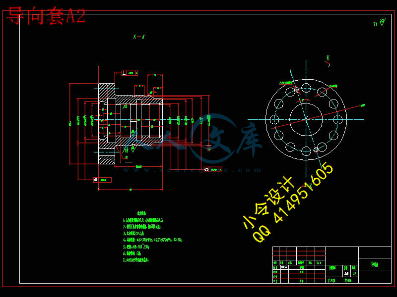
缸筒A2.dwg
缸筒A2.dwg

数控车床液压尾座设计【13张CAD图纸+毕业论文】【答辩通过】

收藏

压缩包内文档预览:
预览图
编号:437298    类型:共享资源    大小:3.24MB    格式:RAR    上传时间:2015-05-30 上传人:好资料QQ****51605 IP属地:江苏
45
积分
关 键 词:
数控车床 液压 设计
资源描述:

【温馨提示】 购买原稿文件请充值后自助下载。

[全部文件] 那张截图中的文件为本资料所有内容,下载后即可获得。


预览截图请勿抄袭,原稿文件完整清晰,无水印,可编辑。

有疑问可以咨询QQ:414951605或1304139763


车床尾座套筒液压装置设计

摘要

   为了完成本课题的设计,在设计之前的准备工作必须做好,首先是搜集和分析资料,主要包括国内外数控机床的发展现状;液压技术和液压传动系统的基本资料;同等机床液压尾座的图纸和资料等。其次是初步确定液压尾座的总体布局,包括配置形式、液压系统的布置及选择液压能源及相应的配套元件等。最后主要是关于尾座的设计计算。

数控机床变档卡紧及尾座顶紧的控制方式基本上是手工控制,在通常的加工过程中,需先用手工控制的方式完成变档和卡紧工作,然后再进行装夹,在装夹完毕后还需要使用手工控制的方式完成尾座的顶紧工作。由此可知,在数控机床的加工作效率效率并不高,而且工人劳动强度大,耗时又耗力,还会增加企业成本。因此,本课题研究所要达到的预期效果是在数控车床加工过程中,当需要使用尾座时,使用本课题所设计的尾座可以提高加工过程的机械化和自动化水平,提高生产效率,降低工人的劳动强度,降低企业成本。

关键词:数控机床;尾座;液压系统;液压缸  


                           Abstract


  To accomplish this design, I collected and analysed the information before the design, including domestic and international development of CNC machine tools; hydraulic system of hydraulic technology and the basic information; equal hydraulic machine Tailstock the drawings and information . Then is tentatively determined the overall layout of hydraulic Tailstock, including the allocation of form, layout and the hydraulic system of hydraulic energy, and select the appropriate matching components, such as. This was followed by the main Tailstock the design and calculation.

CNC machine tools changed file cards bear and Tailstock top tight is basically manual control, in the conventional process, the change required manual card file and clamping a tight and then again after the fixture also need to use a manual Tailstock The top tight. Therefore, in the process of CNC machine tools in efficiency is not high, workers in labor intensity and great. Therefore, the issue of the Institute to achieve the desired results in the CNC lathe processing, when the need to use Tailstock, the use of this issue by the Tailstock design can improve the process of mechanization and automation level, increase production efficiency and reduce Workers in the labor intensity.

Key words:Numerically-controlled machine;Tailstock;Hydraulic system;Hydraulic cylinder inside diameter


目录

1 绪论 1

1.1 研究背景和意义1

1.2 液压传动介绍1

1.3 国内外数控机床的发展现状2

1.3.1 国外数控机床发展现状2

1.3.2 国内数控机床发展现状3

1.4 本文研究对象4

2 液压尾座液压传动总体设计5

2.1 尾座简介5

2.2 回路设计5

2.2.1 液压尾座顶针液压回路6

2.2.2 液压尾座顶针夹紧液压回路7

3 尾座部分的设计9

3.1 液压系统压力9

3.2 顶针油缸的计算9

  3.2.1 顶针轴向力9

  3.2.2 液压油缸计算10

3.3 液压泵的设计12

  3.3.1 液压泵工作压力的确定13

  3.3.2 液压泵流量的确定13

  3.3.3 电动机功率的确定15

3.4 液压元件的选择16

  3.4.1 油管及管接头16

  3.4.2 过滤器的选择16

  3.4.3 油箱的选择17

  3.4.4 油箱容积的确定17

3.5 液压系统的性能验算 18

  3.5.1 液压系统压力损失计算18

  3.5.2 液压系统发热温升的验算19


4 液压尾座结构设计21

4.1 液压尾座箱体设计21

4.2 尾座顶尖的设计21

4.3 尾座主轴的设计21

4.4 尾座导轨的设计22

4.4 尾座孔系设计23

      4.4.1 套筒与尾座体的配合24

4.4.2 套筒与顶尖、尾座活塞轴的配合24

4.4.3 孔和键的设计24

5 尾座精度的设计26

5.1 表面粗糙度的确定26

5.2 尾座与机床形位公差的确定26

5.3 底面及立导向面形位公差的确定26

结  论28

参考文献29

致  谢30

毕业设计(论文)知识产权声明31          

毕业设计(论文)独创性声明32


1 绪论

1.1 研究背景和意义

随着科技的进步,生活水平提高,为了减小工人工作强度,自动化技术被广泛运用到各行各业。自动化(Automation)是指机器设备、系统或过程(生产、管理过程)在没有人或较少人的直接参与下,按照人的要求,经过自动检测、信息处理、分析判断、操纵控制,实现预期的目标的过程。自动化技术广泛用于工业、农业、军事、科学研究、交通运输、商业、医疗、服务和家庭等方面。采用自动化技术不仅可以把人从繁重的体力劳动、部分脑力劳动以及恶劣、危险的工作环境中解放出来,而且能扩展人的器官功能,极大地提高劳动生产率,增强人类认识世界和改造世界的能力。因此,自动化是工业、农业、国防和科学技术现代化的重要条件和显著标志。液压自动化技术被运用到数控车床,减小了工人的工作强度和提高了加工质量。

数控机床给机械制造业带来了革命性的变化。数控加工具有如下特点:加工柔性好,加工精度高,生产率高,减轻操作 者劳动强度、改善劳动条件,有利于生产管理的现代化以及经济效益的提高。数控机床是一种高度机电一体化的产品,适用于加工多品种小批量零件、结构较复杂、精度要求较高的零件、需要频繁改型的零件、价格昂贵不允许报废的关键零件、要求精密复制的零件、需要缩短生产周期的急需零件以及要求100%检验的零件。数控机床的特点及其应用范围使其成为国民经济和国防建设发展的重要装备。

目前,我国已经熟练掌握了液压传动技术,但是在某些环节上还不及发达国家,但是在五星红旗的照耀下,一切问题都将被我们所克服。社会主义制度的优越性决定了液压传动技术绝对能发挥其长处。它不仅能为我国的经济建设带来高度的生产力和巨大的经济效益,而且将为我国的宇宙开发、海洋开发、核能利用等新兴领域的发展做出卓越的贡献。数控机床是一种装有程序控制系统的自动化机床。该控制系统能够逻辑地处理具有控制编码或其他符号指令规定的程序,并将其译码,从而使机床动作加工零件。数控机床含盖了自动化技术、计算机技术、伺服驱动、精密测量和精密机械等各个领域的技术成果,是一门新兴的工业控制技术。

随着国内数控机床的迅速发展, 数控机床的应用普及,数控机床出现故障高发时段。然而,目前的数控维修工作混乱无序,根本不能适应数控行业快速发展的步伐。为了使数控维修工作适应现代化制造业的发展,提高数控设备维修质量,那么规范数控维护也将会增加难度,所以要大号基础,热心研究。


1.2 液压传动介绍

   液压传动是根据17世纪帕斯卡提出的液体静压力传动原理而发展起来的一门新兴技


术,是工农业生产中广为应用的一门技术,液压传动是以流体作为工作介质对能量进行传动和控制的一种传动形式。利用有压的液体经过油压管路以及方向控制阀,压力控制阀等控制原件来实现指定的动作。相对传统的机械传动方式来说,液压传动具有输出力大,重量轻,惯性小,调速方便以及易于控制等优点,因而广泛应用于工程机械,建筑机械和机床等设备上。

液压传动的发展历史:近代液压传动技术是由19世纪崛起并蓬勃发展的石油工业推动起来的,最早实践成功的液压传动装置是舰船上的炮塔转位器,其后出现了液压六角车床和磨床。第二次世界大战(1941-1945)期间,在美国机床中有30%应用了液压传动。在一些兵器上用上了功率大,反应快,动作准的液压传动和控制装置,大大提高了兵器的性能,也大大促进了液压技术的发展。战后,液压技术迅速转向民用,并随着各种标准的不断制订和完善,各类元件的标准化,规格化,系列化而在机械制造,工程机械,材料科学,控制技术,农业机械,汽车制造等行业中推广开来。由于军事及建设需要的刺激,液压技术日益成熟。20世纪60年代后,原子能技术,空间技术,计算机技术等的发展再次将液压技术推向前进,使它发展成为包括传动,控制,检测在内的一门完整的自动化技术,在国民经济的各个方面都得到了应用。如工程机械,数控加工中心,冶金自动线等。液压传动在某些领域内甚至已占有压倒性优势。

   液压传动有许多突出的优点,因此它的应用非常广泛,如一般工业用的塑料加工机械、压力机械、机床等;行走机械中的工程机械、建筑机械、农业机械、汽车等;钢铁工业用的冶金机械、提升装置、轧辊调整 装置等;土木水利工程用的防洪闸门及堤坝装置、河床升降装置、桥梁操纵机构等;发电厂涡轮机调速装置、核发电厂等等;船舶用的甲板起重机械(绞车)、船头门、舱壁阀、船尾推进器等;特殊技术用的巨型天线控制装置、测量浮标、升降旋转舞台等;军事工业用的火炮操纵装置、船舶减摇装置、飞行器仿真、飞机起落架的收放装置和方向舵控制装置。

   国内外发展现状:今天,为了和最新技术的发展保持同步,液压技术必须不断发展,不断提高和改进元件和系统的性能,以满足日益变化的市场需求。与世界上主要的工业国家相比,我国的液压工业还是相当落后的,标准化的工作有待于继续做好,优质化的工作须形成声势,智能化的工作则刚刚在准备起步,为此必须急起直追,才能迎头赶上。可以预见,为满足国民经济发展需要,液压技术也将继续获得飞速的发展,它在各个部门中的应用也越来越广泛。

1.3 国内外数控机床的发展现状

1.3.1 国外数控机床发展现状

数控车床、车削中心,是一种高精度、高效率的自动化机床。配备多工位刀塔或动力刀塔,机床就具有广泛的加工艺性能,可加工直线圆柱、斜线圆柱、圆弧和各种螺纹、槽、

蜗杆等复杂工件。具有直线插补、圆弧插补各种补偿功能,并在复杂零件的批量生产中发

挥 了良好的经济效果。

   数控(英文名字:Numerical Control 简称:NC)技术是指用数字、文字和符号组成的数字指令来实现一台或多台机械设备动作控制的技术。数控一般是采用通用或专用计算机实现数字程序控制,因此数控也称为计算机数控(Computerized Numerical Control ),简称CNC,国外一般都称为CNC,很少再用NC这个概念了。

   国外数控技术主要以以美、德、日三国为代表。美、德、日三国是当今世上在数控机床科研、设计、制造和使用上,技术最先进、经验最多的国家。美国1952年研制出世界第一台数控机床、1958年创制出加工中心、70年代初研制成FMS、1987年首创开放式数控系统等。数控技术被广泛运用到大量大批生产自动化所需的自动线,,故其高性能数控机床技术在世界也一直领先。当今美国生产宇航等使用的高性能数控机床,国外国家特别重视数控机床主机及配套件之先进实用,其机、电、液、气、光、刀具、测量、数控系统、各种功能部件,在质量、性能上居世界前列。如西门子公司之数控系统,均为世界闻名,竞相采用。日本通过规划、法规(如“机振法”、“机电法”、“机信法”等)引导数控机床工业发展。

1.3.2 国内数控机床发展现状

   我国数控技术的发展起步于二十世纪五十年代,中国于1958年研制出第一台数控机床,发展过程大致可分为两大阶段。在1958~1979年间为第一阶段,从1979年至今为第二阶段。第一阶段中对数控机床特点、发展条件缺乏认识,在人员素质差、基础薄弱、配套件不过关的情况下。在第二阶段从日、德、美、西班牙先后引进数控系统技术,并逐步向前发展。特别是最近几年,我国数控产业发展迅速,1998~2004年国产数控机床产量和消费量的年平均增长率分别为39.3%和34.9%。尽管如此,进口机床的发展势头依然强劲,从2002年开始,中国连续三年成为世界机床消费第一大国、机床进口第一大国,2004年中国机床主机消费高达94.6亿美元,国内数控机床制造企业在中高档与大型数控机床的研究开发方面与国外的差距更加明显,70%以上的此类设备和绝大多数的功能部件均依赖进口。由此可以看出国产数控机床特别是中高档数控机床仍然缺乏市场竞争力,究其原因主要在于国产数控机床的研究开发深度不够、制造水平依然落后、服务意识与能力欠缺、数控,系统生产应用推广不力及数控人才缺乏等。我们应看清形势,充分认识国产数控机床的不足,努力发展先进技术,加大技术创新与培训服务力度,以缩短与发达国家之问的差距。 在20余年间,数控机床的设计和制造技术有较大提高,主要表现在三大方面:培训一批设计、制造、使用和维护的人才;通过合作生产先进数控机床,使设计、制造、使用水平大大提高,缩小了与世界先进技术的差距;通过利用国外先进元部件、数控系统配套,开始能自行设计及制造高速、高性能、五面或五轴联动加工的数控机床,供应国内市场的需求,但对关键技术的试验、消化、掌握及创新却较差。至今许多重要功能部件、自

动化刀具、数控系统依靠国外技术支撑,不能独立发展,基本上处于从仿制走向自行开发

阶段,与日本数控机床的水平差距很大。存在的主要问题包括:缺乏象日本“机电法”、“机信法”那样的指引;严重缺乏各方面专家人才和熟练技术工人;缺少深入系统的科研工作;元部件和数控系统不配套;企业和专业间缺乏合作,基本上孤军作战,虽然厂多人众,但形成不了合力。我们国家机床业最薄弱的环节在数控系统。机床精度 (1)机械加工机床精度分静精度、加工精度(包括尺寸精度和几何精度)、定位精度、重复定位精度等5种。(2)机床精度体系 目前我们国家内承认的大致是四种体系:德国VDI标准、日本JIS标准、国际标准ISO标准、国标GB,国标和国际标准差不多。(3)看一台机床水平的高低,要看它的重复定位精度,一台机床的重复定位精度如果能达到0.005mm(ISO标准.、统计法),就是一台高精度机床,在0.005mm(ISO标准.、统计法)以下,就是超高精度机床,高精度的机床,要有最好的轴承、丝杠。(4)加工出高精度零件,不只要求机床精度高,还要有好的工艺方法、好的夹具、好的刀具。

1.4 本文研究对象                                                

   在机械制造行业中,数控车床被广泛用来加工盘类或轴类零件。在加工这类零件的时候,有许多零件需要用内孔作为定位夹紧面来进行外圆、端面、螺纹等的切削加工。目前,用数控车床对这类零件进行加工时的定位装夹通常采用人工手动夹紧,因此数控车床的尾座结构普遍是手动控制结构,用手动方式旋转手轮带动尾座套筒使尾座上的顶尖伸出以顶紧工件,实现对工件的定位,再扳动手柄实现锁紧。采用这种手动控制方式,工作效率低,劳动强度大,夹紧力大小难以精确控制,定位准确性和稳定性都比较差。故设计一种车床尾座的液压控制机构代替传统的手动式控制是完全有必要的,可进一步完善和提高数控车床的自动化程度。数控车床的尾座是在加工轴类零件时,使用其顶尖顶紧工件,保证加工的稳定性。尾座的运动包括尾座体的移动和尾座套筒的移动。

   尾座体的移动有两个作用:一个作用是在加工轴类零件时,将尾座调整到使用位置;另一个作用是在加工短轴和盘类零件时,将尾座调至非干涉位置。尾座套筒的移动是为了使顶尖顶紧或松开工件的,通常是由液压缸控制的。

   本文主要研究数控机床尾座的设计,并将液压传动运动运用到尾座上,实现尾座的自动顶紧与松开。设计出液压尾座的结构以及液压传动图、液压缸。其要求具体参数:数控车床的切削用量f=0.1-0.3mm/r;切削速度为v=50-80m/min;最大车削工件直径400mm,最大加工长度350mm,切削粗糙度为Ra1.6-3.2μm。


内容简介:
40KSMEJournal,VolA,No.1,pp.40-47,1990.ANALYTICALANDEXPERIMENTAL MOTION ANALYSISOFFINGER FOLLOWER TYPE CAM-VALVE SYSTEMWITH A HYDRAULICTAPPETWon-Jin Kim-, Hyuck-Soo Jeon- and Youn-Sik Park-(Received September11,1989)Inthis paper, the motionofa fingerfollower type cam valve system with a hydraulic tappet was analytically and experimentallystudied. First, the exact contact point between cam and follower for each corresponding cam angle was searchedbykinematicanalysis. Then a 6degree of freedomlumpejspringdampermass model was constructed to simulate the valve motion analytically.When constructing the model, mostofthe parameters were experimentally determined.Butseveral values which are difficult toderive experimentally such as damping coefficients were determined with engineering intuition.Inorder toshowthe effectivenessof the analyticalmodel,the predicted camvalve motion was directly compared with the measured valve and tappet motions.Key Words:FingerFollower(OscillatiwRoller Follower), Overhead Cam(OHC), CamValve System, Jump, BounceNOMENCLATURE-Ae:Equivalent cross-sectionalareaof oil chamber in tappet,m2C.C.2C.3:Equivalent damping coefficients of valvespring,N/mC.e:Damping coefficient of valve seat, N-s/mc,f,CVf,Cfe:Equivalent damping coefficients ofcontactpoint,Ns/mc,p:Equivalent damping coefficient of tappet:N-s/m/0:Fundamental natural frequency of valve spring, HzFo:Initial compression force of valve spring,NFif Fvf Ffe:Contact forcesateach contact point,NFifO,Fvfo, Ffeo:Initial contact forcesateach contact point,Nh:Clearance between cylinder and plunger, mmHe:Lengthofcompressed oil chamber, mmIf:Follower moment of inertia,kg-m2Ko:Valve spring stiffness, N/mKe:Equivalent stiffness oftappetoil chamber,N/mK.1K.2K.3:Equivalent stiffness coefficients of valvespring,N/mK.:Stiffness oftappetsoft spring,N/mK,f, Kvf, Kfe:Equivalent stiffness coefficients of contactpoint,N/mL:Plunger length, mmLf:Leverarmof forceFfmmLvf:Leverarmof forceFvf,mmme: Mass of oil insidetappetoil chamber, kgMf:Follower mass,kgMt:Equivalenttappetmass,kgMv:Equivalent valve mass, kgDnpartmentofMechanical Engineering, Korea Advanced Institute of Science and Technology,P.O.Box150Cheongruarlg,Seoul 130-650, Koeramm2: Equivalent valve spring masses, kgRp:Radiusoftappetplunger, mmRe:Radius of cam base circle,mmRab:Distance fromcampivot to follower pivot, mmR, : length of oscillating roller follower, mmRf:Radius of roller in roller follower model, mmYf:Follower displacement, mmY,:Tappetdisplacement,j.tmYe:Cam lift, mmYv:Valve displacement, mmY.Y.2:Displacements of equivalent valve spring masses,mm8f:Angularrotationof follower,radianj.t:Oil viscosity coefficient, Pa-sE:Bulk modulus,N/m28:Angular rotation of cam,radian1. INTRODUCTIONWhen designing a cam-valvetrainofinternal combustionengine, therearemany thingstobe considered suchasvalvelift area, peakcamacceleration, propercamevent angle,rampvelocity, etc. As increasingtheoperation speed ofinternal combustion engine, the dynamic effect of cam-valvesystem becomes more important. Recently, some researcheshave been done focusing the dynamic effects on cam-valvesystem. Akiba,etal.(1981) constructed a 4 degree of freedommodel to analyzeanOHV (Overhead Valve) type cam-valvesystem and studiedthedynamic effects onthesystem motion.Jeanand Park(1989)tried to analyze the same type of valvesystem with a lumped mass dynamic model and designed anoptimalcamshape considering dynamiceff.Pisano andFreudenstein(1982)developed a dynamic modelofa highspeed valve system capable of predicting both normal systemresponse as wellaspathological behavior associated withonsetof jumping,bounce,andspringsurge.Previousresearches in high-speedcamsystem had been almost focusedon systems with a constant rocker-armratioand onthevalve.ANALYTICALANDEXPERIMENTAL MOTIONANALYSISOF FINGER FOLLOWERTYPECAM-VALVESYSTEMWITH .41train separation phenomena. Especially, the analysis for camsystem having a hydraulic tappet has not been thoroughlystudied.In this work, an OHC cam-valve train with a hydraulictappet and a finger follower, was analyzed analytically withlumped mass model and its reliability was verified experi-mentally.Thecam-follower system usedinthis work ischaracterized with its complex dynamics of hydraulic tappetand the nonlinearity from varying rocker-arm ratio.Therocker-arm ratio deviates as much as34percent from abaseline value of I.47as the contactpoirUbetweencamandfollower moves. The pivot end of the oscillating follower issupported notata fixed point butata vertically moving pivotmountedattop a hydraulic tappet.Themajor role of thehydraulic tappet is to remove the valve lash which givesharmful impact within valve train. But in high operatingspeed region, the hydraulic tappet can be oprated abnormallyand can make an unusual valve train motion. Therefore, thecharacteristics of the hydraulic tappet must be consideredinvalve train dynamic model.Theprimary research for asimilar cam system was done by Chan and Pisano(1987).They established six degrees of freedom model consideredtranslational and rotational motion of oscillationg followerand valve. But they used a simple single degree of freedommodel for the hydraulic tappet. They focused only on analyti-cal work and did not attempttoverify the results experimen-tally2.VALVETRAINMODELINGTAPPETFig.1:0:bIiP:VALVEI()ISPRINGIf0:IIVALVESEATSchematicoffinger follower valve trainTheactual overall shape of an OHC type cam-valve trainis shown in Fig.I.Inorder to describe the valve motionprecisely, the valve train was modeled with 6 degree offreedom. Those are valve opening and closing motion,Yv,hydraulic tappet translational motion,Yfinger-followertranslational and rotational motion,Y/and 8/, and twoadditional degree of freedomYS!andYS2which representvalve spring translational motion.Thereason for takingvalve spring motionsYS!andYS2is to consider valve springsurge phenomenon.Itis knownthatvalve spring surge affectsgreatly on valve motion especially when the operation speedis high. Because camshaft can be consideredasrigid andfixed on its bearing, its dynamic characteristics was neglect-edinthe model.All thecompotsand the contact points of the cam-valvesystem wererueledwith equivalent mass, springs anddampers asshoinFig.2.Thedetails of modeling proce-dureareexplainedasfollows.2.1ContactPointModelingAs showninFig. 1the finger-follower type cam-valve trainCAMTAPPETIVALVESEATVALVESPRING. CseFig. 2Usedmodel42Won-inKim,Hyuck-SooJeonand Youn-Sik ParkTheequivalent mass(Me)offinger followerateach contactpoint can be obtained fromEq.(2)asconsidering the followermoment of inertia(If).whereMfis the follower equivalent mass andIis the dis-tance between follower mass center and each correspondingcontact point.Theequivalent mass of camshaftatcontactpoint is estimated to infinity as assumingthatit is rigid andhas4 contact points between valvetraincomponents. Thosearebetween follower and tappet, follwer and cam, followerand valve, and valve seat and valve.Thecontactatvalve seatoccurs periodicallyasdifferent with others which shouldmaintain continuous contact.Theequivalent valveseatstiff-ness(Kse)anddamping (Cse)cofficients weretakenfrom thepreviously published literature (Chan and Pisano,1987).Onthe other hand, the equivalent damping and stiffness coeffi-cientsatother contact points were predicted by Hertz con-tacttheory utilizing shape factor, modulus of elasticity, andPossons ratio.AJ;assuming the proper range of contactforces, the corresponding contact stiffness was calculated byHertz contact theory.Thenthe equivalent stiffnessesateachcontact point were determined by least squareerrorcurve fitfrom obtained contact stiffnesses (Roark and Young,1976).Itwas assumedthatthe contact between tappet and follower isaninternal contact of two spheres, between cam and follweris a contact of two cylinders, and between follower and valveis a contact of a cylinder on a plane.Thedamping coefficientsateach contact point wereassumedas0.06and the critical damping coefficient(Ccr)canbe calculated using Eq.(I). WhereM,andMzarethe equiva-lent masses of each contacting component. it was assumedthatthe equivalent masses of each contacting component(M,andMz)areconnected by a spring and a damper.(3)2m,=mz=:rKol(flo)8Kl=K.a=:rKo,K.z=4Ko2.3HydraulicTappetModelingTheleft side of Fig. 3 shows the cross section shape ofhydraulic tappet. Oil enters through entrance and fills thecentral cavity of tappet plunger. As the plunger moves down,the check valve is closed and the oil flows from oil chamberthrough narrow clearance between plunger and cylinder andgenerates damping force. In next step, when the plungermoves upward due to the spring positioned inside of oilchamber, the check valve is opened and oil is refilled in oilchamber.Thehydraulic tappet was simplifiedasshown in theright side of Fig.3 and the equivalent stiffness of the tappetwas estimated by assumingthatthe fluid is totaly compres-sive and there is no flow through diametral clearance.TheThespringrateand fundamental natural frequency of usedvalve springare35KN1mand 504.46Hz, respectively.Thedamping is assumed as4%proportional viscous damping.fixed on its bearing.Theequivalent masses of tappet andvalveatother contact points areM,andMv.2.2ValveSpringModelingIn order to consider valve spring surge effect, the valvespring was modeled with 2masses(m,andmz),3springs(KShKsandKsa),and 3 dampers(CshCszandC.a)with 2 degreeof freedom(sandz).Several assumptions were made inthe valve spring modeling. Those are; ( i ) symmetricity(K.,=KsaandC.,=Csa),(ii)equivalency ofstaticstiff-ness and fundamental natural frequency between model andfundamental natural frequency between model and actualsystem,(iii)proper damping assumption.As consideringthatvalve spring is in clamped-clampedboundary conditon, the secondary natural frequency of valvespring becomes twice of the fundamental spring naturalfrequency. All the above assumptions give(1)(2)C=2/KM,MzcrM,+M.OILENTRANCE-hJ.-0)Mf0.05981K:5.92x 10;1.1280,0)h1.1527X10-Kif5.52X10Cf118.97Mv0.08544Kfc8.37x 10Cfc197.97m,0.0092KVf4.33x 10CVf94.13m20.0092K 1.31x10C634.77K.K.9.33xlOCu.C.a2.35!5K.21.40x 10C.23.534relationship is(4)was carefully calculated considering its geometrical shape.All the used mass. stiffness and damping values were sum-marizedinTable2.whereaandpcan be determined by comparing modelsimulation result with experimentally measured record.2.4Mass and MomentofInertia ModelingValve, tappet plunger, and follower mass(Mv,Mt,andMf)were directly measured.Thefollower moment of inertia(If)whereEis bulk modulus,Heis the length of compressed oilchamber, andAeis plunger area.Onthe other hand. the equivalent damping coefficient wasestimated by assumingthatthe oil is totally incompressive.Itwas assumedthatthe excessive oil due to plunger motionflows completely through the diametral clearance. Then theequivalent damping value can be predicted from the theory offluid mechanics.Itis knownthatthe damping coefficientchanges with the direction of plunger motion. Those are(7)X=(Rc+S)cosO-sinOY=(Rc+S)sinO+cosO3.1Kinematical AnalysisWhen searching the point where cam and follower con-tacts, the tappet was considered fixed point. It was foundthatthe influence of tappet motion upon contact point is negli-gible.Thetappet motion, which isatmostO.I(mm).is enoughsmall and can be considered negligible and differs in order ofmagnitude with cam lift. When the camdatais given withdesired cam lift(S),the actualcamshape(X,.Y),contactingwith a flat follower, can be obtained fromEq.(7)Thebaselinerocker-arm ratio is1.47and the fluctuating range of rockerarmratio varies from1.15to1.97during the cycle.Thefinger-follower type ORC cam-valve system is char-acterized with varying rocker-arm ratio with cam shaftrotations. So the kinematical analysis to search theexactcontact points between cam and follower is inevitable beforedoing dynamic analysis.3.ANALYSISwhereRcis cam base circle.0is cam angle,Sis flat followerdisplacement, andXandYspecify cam shape.Theincrement ofSabout0can be calculated with cubic spline interpolation (Shoup.1979).When the cam shape(X.Y)is given,the contact point between cam and follower can be found bykinematical analysis. Fig. 4 shows the idea how to find thecontact point.Theprocedures are. first,rotatethe followeraround a fixed cam. then find out the locus of followercenter(CC) Next. search the contact point for each followerrotatingangle(Oc)using the principlethatthe contact point is(6)whereJ1.is oil viscous coefficient,Lis plunger length,Rpisplunger radius, andhis clearance between cylinder andplunger. All tappet dimensions and propertiesaregiven inTable1.Equations(4,5)derived above are two extreme cases. oneis assumed totally compressive and the other is totally incompressive. Butinactual situation, the dragforce(Fd)duetoplunger motion will be placed somewhere in the middle of thetwo values (Kreuter and Mass.1987).As introducing twocoefficientsaandP(OaI,Op1),the drag forcecanbemodeledasEq.(6).44Won-JinKim,Hyuck-Soo JeanandYoun-Sik Parkthe point where the line connectingcamcenter(A)and thefollower center (any point in locusCC)crosses with thetangent lineatthe correspondingcamangle.Thenthe contactpoint locuscanbe determined byrotatingthe searchedcontactpointtothebackwardas much asthecorrespondingcamangle(8e).Thekinematic dimensions of Fig. 4aregiveninTable3.Theinstantaneous rocker-armratiois calculatedby dividingthetotallength of the finger-follower with thehorizontal distance betweenthepivot point and cam andfollowercontactpoint for each corresponding cam angle.Theobtained contact- point locus and the corresponding fluctuat-ing rocker-armratiofor this studyareshown in Fig.5(a),(b).3.2Dynamical AnalysisWhenthecamshape, operation speed and follower shapearegiven, the equationsofmotioncanbe easily constructed.Duringthecalculation of contact point, all dimensions ofLfc(distance betweentappetand follower mass center),LoAdis-tance betweencamcontactpoint and follower mass center),andLOf(distance between valve and follower mass centercanbe obtained. Here,LuandLVfgiven inTable3are constant.Lfcis calculated with instantaneouscontactpoint.Theeffectof the fluctuating rocker-armratioon the valvetraindynamics is represented by varyingLfc.Thenthe equationsof motioncanbe constructed asFOLLOWERM,Y,=Fu-K,pY,-C,pY,MfYf=Ffc -Ff- FOffij,=FfLf+FfcLfc- FofLofmlYSI=KSI(Yo-YSI)+CSI(Yo-YSI)- Ksz(YSI- Ysz) -Csz(YSI - Ysz)mzYsz=Ksz(YSI-Yd+Csz(YSI-Ysz)(8)-KSIYsz-CSIYszmoYo=Fof- KseYo- CseYo-KSI(Yo- YSI)- CSI(Yo-YSI)ifYoFo/KsewhereFois the precompressed force of valve spring (in thisstudy,Fo=275N)Thecontact forcesFfFfc,andFOfcanbe determinedasEq.(9).(10)34.0014.2222.53unit:mm36.4031.6713.00Table 3Kinematic dimensionsBetweentappetand follower:Yf-Y,-Lf,sin8f-Ffo/KfBetween cam and follower:Ye- Yf- Lfesin8f-Ffeo/KfeBetween valve and follower:Yf- Yo+ Lofsin8f-12-8-4048x-coord.(mml(a)2.50.2.0.,L.EL.1.5flIIL.1.00.51001100cam-angle(deg.1(b)Fig. 5Contact point locus and fluctuating rocker arm ratioANALYTICALANDEXPERIMENTAL MOTION ANALYSISOFFINGER FOLLOWER TYPE CAM-VALVESYSTEMWITH45.Im.expo100l:70,i1:140-u.!i-100-203070110ca.-angIe(deg. )(a)150190.-,.1.expo100l:70ie400.!2-100-2030Fig. 7120i:OIl.,OIl90I0-0SOClI:0Cl8,30CI.k:l090014002000260Q3200ell_shllftspeed(rpm)Fig.8Maximum tappet leakage down versus camshaft speed70110150190call1-ang)e(l:Ie9)(b)(a)Camshaft speed900rpm(b)Camshaft speed1600rpmTappet leakagedown9,10,11, we can concludethatthe 6 degree of freedom lumpedmass model used in this work is quite reliable to predict valvemotion even in high operating speed.Figure12shows a sample of contact forcesatall contactpoints when the operation speed is2450rpm.Itcan beobservedthatthe contact forcesatthe first peak position arereduced andatthe second peak position are accentuated ascompared with the value of constant rocker-arm ratiocamsystem duetofluctuationg rocker-arm ratio. As examiningthe contact force record, we can easily predict the mostpossibleareaand correspondingcamangle where unwantedvalvetrainseparationcanbe occurred.Theexperimentally verified model can be expanded notonly to predict the maximum operation speed but also toFig.6Experimental apparatus5.RUSULT AND DISCUSSION4.EXPERIMENTFigure 7 compares the measured and simulated tappetleakage downatcamshaft speed900and1600rpm. Figure 8shows the measured maximum tappet leakage down.Itisknownthathydraulic tappet is stiffened as the speed ofcamshaft is increased.Themaximum compression of thehydraulic tappet was about100/lmat800rpm and approa-ched a limit of about60/lmasthe camshaft speed goes beyond3000rpm,asshown in Fig.8.As explained before, themeasured tappet motion was used to determine the weightingparamentersaand3,which determine the plungerdragforce, by least square curve fit between the measurement andthe analysis record.Itwas foundthatthe weighting parame-ter varies with operation speed. For example,aand3where0.0071and0.28when camshaft is driven by900rpm, but thevalues were changed to0.0094and0.30when the runningspeed was raised to 1600rpm.Figures9,10,11show the measured and simulated valvedisplacementsandvelocities.Thevalvevelocitywasobtained by differentiating the measured valve displacementrecord.Figure 9 compares the measured and analyzed valvemotion when the camshaft was drivenat600rpm.Itcan besaidthatthe model can simulate not only the peak valvedisplacement but also thecamevent angle quite precisely.Figure10,11show the analysis and measurement when thecamshaft speedsare1600rpm 2450rpm. As glancingatFigs.Inordertoprove the effectiveness of the model simulation,experimental work was done and compared each other.Figure6.shows the experimental apparatus. While theOHC type cam-valve train was driven by a 100kWDCmotor, valve displacement and hydraulic tappet motion weremeasured simultaneously.Thevalve displacement was mea-suredwithanopt-follow(noncontacttypeopticaldis-placement measurement device), and the tappet motionwasmeasured with a gap sensor. An encoder was placedattheone end of camshaft in order to average the measured signal.Specialcarewas taken to eliminate problems caused bycirculating engine oil. All the measurement were doneasvarying the camshaft running speed from600to 2450rpm.Won-jinKim,Hyuck-Soo jeonandYoun-Sik Park180180-81._-expo-81-expo4590135cam-ang1e(deg. )10.(;,.-,E7.5.,CQJE5.0QJUlQ.2.5tlU0.00600u300QJen-EB0-.,u0-300QJ-60004590135cam-angIe(deg. )Fig.11Valve displacement and velocity (camshaft speed2450rpm)180180-si.-expo4590135call1-angleldeg. )4590135cam-angleldeg.)4610.0E7.5.,CQJE5.0QJUlQ.2.5tlU0.00200U100QJtl-EU-0.,u0-100aJ-2000Fig.9Valve displacement and velocity(camshaft speed600rpm)400.-.,4590135180cam-ang1eIdeg.)(h)4590135180cam-angleldeg. )(a)16001200B800400oo16001200800f400o_.L-J:O:C:=.:;.;-.L-.-o1804590135cam-ang e(deg.)o0.010.
温馨提示:
1: 本站所有资源如无特殊说明,都需要本地电脑安装OFFICE2007和PDF阅读器。图纸软件为CAD,CAXA,PROE,UG,SolidWorks等.压缩文件请下载最新的WinRAR软件解压。
2: 本站的文档不包含任何第三方提供的附件图纸等,如果需要附件,请联系上传者。文件的所有权益归上传用户所有。
3.本站RAR压缩包中若带图纸,网页内容里面会有图纸预览,若没有图纸预览就没有图纸。
4. 未经权益所有人同意不得将文件中的内容挪作商业或盈利用途。
5. 人人文库网仅提供信息存储空间,仅对用户上传内容的表现方式做保护处理,对用户上传分享的文档内容本身不做任何修改或编辑,并不能对任何下载内容负责。
6. 下载文件中如有侵权或不适当内容,请与我们联系,我们立即纠正。
7. 本站不保证下载资源的准确性、安全性和完整性, 同时也不承担用户因使用这些下载资源对自己和他人造成任何形式的伤害或损失。
提示  人人文库网所有资源均是用户自行上传分享,仅供网友学习交流,未经上传用户书面授权,请勿作他用。
关于本文
本文标题:数控车床液压尾座设计【13张CAD图纸+毕业论文】【答辩通过】
链接地址:https://www.renrendoc.com/p-437298.html

官方联系方式

2:不支持迅雷下载,请使用浏览器下载   
3:不支持QQ浏览器下载,请用其他浏览器   
4:下载后的文档和图纸-无水印   
5:文档经过压缩,下载后原文更清晰   
关于我们 - 网站声明 - 网站地图 - 资源地图 - 友情链接 - 网站客服 - 联系我们

网站客服QQ:2881952447     

copyright@ 2020-2025  renrendoc.com 人人文库版权所有   联系电话:400-852-1180

备案号:蜀ICP备2022000484号-2       经营许可证: 川B2-20220663       公网安备川公网安备: 51019002004831号

本站为文档C2C交易模式,即用户上传的文档直接被用户下载,本站只是中间服务平台,本站所有文档下载所得的收益归上传人(含作者)所有。人人文库网仅提供信息存储空间,仅对用户上传内容的表现方式做保护处理,对上载内容本身不做任何修改或编辑。若文档所含内容侵犯了您的版权或隐私,请立即通知人人文库网,我们立即给予删除!