单刃刀具-外文文献.doc

CA-20地下自卸汽车工作、转向液压系统参数计算及轮边制动器的设计【14张CAD图纸+毕业论文】

收藏

资源目录
跳过导航链接。
压缩包内文档预览:
预览图 预览图 预览图 预览图 预览图 预览图 预览图
编号:437375    类型:共享资源    大小:2.87MB    格式:RAR    上传时间:2015-05-30 上传人:好资料QQ****51605 IP属地:江苏
45
积分
关 键 词:
ca 20 地下 汽车 工作 转向 液压 系统 参数 计算 制动器 设计
资源描述:

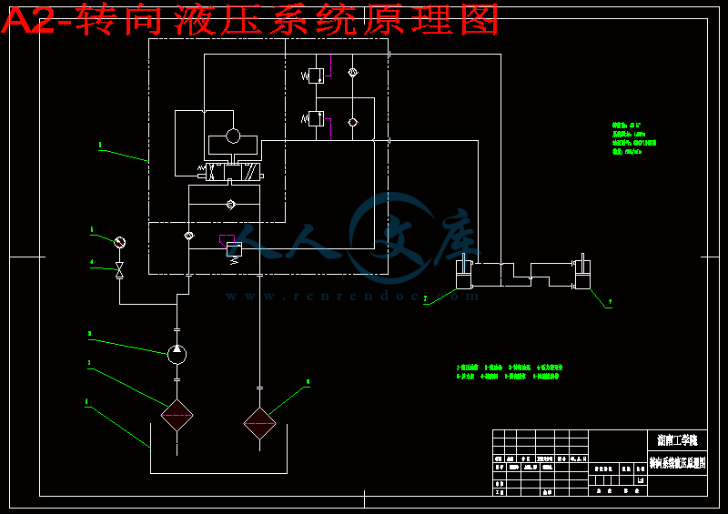
摘  要:详细介绍了CA-20地下自卸汽车工作液压系统和转向液压系统的设计,为四个步骤:根据各个系统的功能和整车布置拟定液压系统原理图;根据翻倾及转向角度分别计算工作油缸的行程;根据各系统所受的最大作用力确定系统压力;根据各系统的系统压力和流量选定各系统的泵及其他液压元件。实践CA-20地下自卸汽车液压系统是安全、可靠和高效的。

关键词:地下自卸汽车;工作液压系统;转向液压系统;泵;油缸;

Abstract: In this paper the design of the hydraulic systems of working and steering for CA-20 Rear Dump Truck is introduced. The design include four steps. First of all according to the feature of each hydraulic system, we can draw the principle diagrams of the hydraulic systems of working and steering. Then we can calculate the travels of the dumping cylinders and steering cylinders by the angles of dumping and steering. And then we can decide the pressure of each hydraulic system through the maximal force on each system. At last may chose the pumps and other hydraulic parts according to the pressure and the flow of each hydraulic system, The fact has proved that the hydraulic system of the truck is safe, reliable and efficient.

Key words:  Rear dump truck   Hydraulic system of working   hydraulic system of steering  Pump  Cylinder


目录

一、绪论

(一)立项背景                                1

(二)国内外研究现状与发展趋势 3

(三)项目实施的主要内容、技术关键与创新点、预期目标      5

(四)应用或产业化前景与市场需求                          6

(五)现有工作基础、条件和优势                            7

二、液压系统参数计算    

(一)概述                                          8

(二)工作液压系统参数计算    8

(三)转向液压系统参数计算12  

(四)变矩器与发动机优化匹配MATLAB程序的编制   18

(五)液压缸装配、维护、修理工艺                       30

                                                        37

三、参考文献     50

谢辞51

附页52


一、绪 论


(一)立项背景:

地下自卸汽车是实现无轨开采技术的主要运输设备,它具有机动灵活和经济的优越性,广泛用语条件适宜的地下矿山。随着无轨采矿技术的发展,对地下自卸汽车的需求量也愈来愈大,对它的经济性、生产能力与可靠性的要求也愈来愈高,生产地下自卸汽车的厂家也愈来愈多。除了专门生产地下自卸汽车的厂家之外,生产露天自卸汽车的厂家也纷纷将露天自卸汽车改造后用于地下,企业之间的竞争愈来愈激烈。各企业为了适应市场的变化,提高市场的竞争力,不断推出新技术、新品种、新结构和新材料,促进了无轨采矿技术与设备的发展。

国内研制地下自卸汽车始于20世纪70年代中期,由于各种原因,至今发展不快,只有几个生产厂,技术水平只相当于国外20世纪80年代末的水平,数量与质量也远远满足不了国内矿山发展的需要。我们加入了WTO之后,地下自卸汽车行业面临着极大的压力和挑战,为了对付这严峻的形势一方面要引进更多更好的国外产品与相关技术,另一方面必须迅速发展民族工业。

进入21世纪以来,我国的矿业形势发生了很大的变化。许多露天矿山,由于开采深度不断增加,为了降低开采成本、保护环境,这些矿山必须由露天开采转入地下开采。据有关协会统计,我国的铁矿山在5年后,露天开采与地下开采的比将由目前的7∶3转变成3∶7,由此可见,地下矿山设备在我国的应用前景十分广阔。据有关资料分析,我国今后地下矿山自卸汽车的需求量将呈逐年上升的趋势。目前的年需求量约30台左右,5年后年需求量约120台左右。

由于历史的原因,我国在地下矿山运输设备领域装备十分落后,尽管经过太原重型机械厂、北京矿冶研究总院、核工业第六研究所、衡阳有色冶金机械厂、金川有色公司、长沙矿山研究院等单位的努力,分别对5t、8t、10t、12t、18t、20t、25t等机型进行了一些研究,取得了一些成功,但这些探索性的研究显然还很不够,而且有些探索显然没有达到预期的目的。因此,直到目前我国可供矿山选用的地下矿山自卸汽车比较少,远远不能满足我国地下矿山运输设备需要。

国外的地下矿山自卸汽车应用得比较好,技术也比较先进,但价格比较高。一般情况是:国外的地下矿山自卸汽车整机的价格是国内价格的2~3倍,而易损件、备件的价格却是6~10倍。因此,发展我国的地下矿山自卸汽车是非常必要的。

20t地下矿山自卸汽车是我国矿山应用较多的一种机型,它比较适合中型规模的地下矿山。我国的有些公司对它有过探索,但没有达到预期的目的,至今没有该产品通过鉴定的报道。因此,我国的20t地下矿山自卸汽车目前还停


内容简介:
译文:Single Point Tools Single-point tools are cutting tools having one cutting part (or chip producing element) and one shank. They are commonly used in lathes, turret lathes, planers, shapers, boring mills, and similar machine tools. A typical single-point tool is illustrated in Fig.2.30. The most important features are the cutting edges and adjacent surfaces. These are shown in the figure and defined as follows:the face is the surface or surface over which the chip flows.The flank is the tool surface or surfaces over which the surface produced on the work-piece passes.The cutting edge is that edge of the face which is intended to perform cutting. The tool major cutting edge is that entire part of the cutting edge which is intended to be responsible for the transient surface on the work-piece. The tool minor cutting edge is the remainder of the cutting edge.The corner is the relatively small portion of the cutting edge at the junction of the major and minor cutting edges; it may be curved or straight, or it may be the actual intersection of these cutting edges.In general, when a tool is applied to a work-piece, its motion relativeto the work-piece has two components:The motion resulting form the primary motion of the machine tool, which can be called the primary motion of the tool.The motion resulting form the feed motion of the machine (Fig.2.31).The resultant of these two tool motions is called the resultant cutting motion and is defined as the motion resulting from simultaneous primary and feed motions.It should be noted that in machine tools where the feed is applied while the tool is not engaged with the work-piece (as in shaping or planning, for example ),the resultant cutting motion is identical to the primary motion. When the feed motion is applied continuously, the angle between the direction of primary motion and the resultant cutting direction is called the resultant cutting-speed angle. This angle is usually extremely small and for most practical purposes can be assumed to be zero. Further, the cutting speed , the instantaneous velocity of the primary motion of the selected point on the cutting edge relative to the work-piece, can vary along the major cutting edge. The feed speed , the instantaneous velocity of the feed motion of the selected point on the cutting edge relative to the work-piece, is constant.Finally, the resultant cutting speed ,the instantaneous velocity of the resultant cutting motion of the selected point on the cutting edge relative to the work-piece, is given by , ,but since for most practical operations is very small, it can generally be assumed that ,. One of the important tool angles when considering the geometry of a particular machining operation is the angle in Fig.2.32 called the major cutting-edge angle .The thickness of the layer of material being removed at the selected point on the cutting edge, known as the under-formed chip thickness chip thickness ,significantly affects the power required to perform the operation. Strictly, this dimension should be measured both normal to the cutting edge and normal to the resultant cutting direction. However, for all practical purposes, since is small, as described above, can be measured normal to the direction of primary motion; thus in Fig.2.32 and all subsequent figures, will be measured this way. From Fig.2.32, therefore, is given by , where is the feed engagement, the instantaneous engagement of the tool cutting edge with the work-piece measured in the direction of feed motion. For single-point cutting operations is equal to the feed, and therefore, .The cross-sectional area of the layer of material being removed (cross-sectional area of the uncut chip) is approximately giver by, ,where is the base engagement, previously known as depth of cut. The back engagement is the instantaneous engagement of the tool with the work-piece, measured perpendicular to the plane containing the directions of primary and feed motion(Fig.2.31). In general the back engagement determines the depth of material removed from the workpiece in a single point cutting operation.Jigs and FixturesIt has already been stated the work-piece must be located relative to the cutting tool, and be secured in that position. After the work-piece has been marked out, it is still necessary to position it with respect to the machine movement, and to clamp it in that position before machining is started.When several identical work-piece are to be produced the need to mark out each part is eliminated by the use of jigs and fixtures, but if a casting or forging is involve, a trail work-piece is marked out, to ensure that the work-piece can be produced from it, and to ensure that ribs, cores, etc. have not become misplaced.Jigs and fixtures are alike in that they both incorporate devices to ensure that the work-piece is correctly located and clamped, but they fifer in that they both incorporate means of tool guiding during the actual cutting operation, and fixtures do not. In practice ,the only cutting tools that can be guided while actually cutting are drills, reamers, and similar cutters; and so jigs are associated with drilling operations, and fixtures with all other operations. Fixtures may incorporate means of setting the cutting tools relative to the location system.The advantage of jigs and fixtures can be summarized as follows:1. marking out and measuring and setting out methods are eliminated;2. unskilled workers may proceed confidently and quickly in the knowledge that the work-piece can be positioned correctly, and the tools guided or set;3. the assembly of parts is facilitated, since all components will be identical within small limits, and trying and filing of work is eliminated;4. the parts will be interchangeable, and if the product is sold over a wide area, the problem of spare parts will be simplified.Bolt holes often have 1.5mm or even 3.0mm clearance for the bolt, and reader may doubt the necessity of making precision jigs for such work. It must remembered that the jigs, once made, will be used on many components, and the extra cost of an accurately made jigs is spare over a large output. Further more, it is surprising how small errors accumulate in a mechanism during its assembly. When a clearance is specified, it is better to ensure its observance, rather than allow careless marking out and machining to encroach upon it.(1) the location of work-piece. Fig 2.27 represent a body that is completely free in space; in this condition it has six degrees of freedom. Consider these freedom, with respect to the three mutually perpendicular axes XX,YY and ZZ. The body can move along these axes; it therefore has three freedoms of translation. It can also rotate about any of the three axes; it therefore has three freedoms of rotation .the total number of freedoms is six. When work is located, as many of these freedoms as possible must be eliminated, to ensure that the operation is performed with the required accuracy. Accuracy is ensured by machining suitable location features as early as possible, and using them for all location, unless other considerations mean the other location features must be used. If it is necessary, the new location features must be machined as a result of location from the former location features.(2) The clamping of the work-piece. The clamping system must be such that the work-piece is held against the cutting forces, and the clamping force must not be so great as to cause the work-piece to become distorted or damaged. The work-piece must be supported beneath t
温馨提示:
1: 本站所有资源如无特殊说明,都需要本地电脑安装OFFICE2007和PDF阅读器。图纸软件为CAD,CAXA,PROE,UG,SolidWorks等.压缩文件请下载最新的WinRAR软件解压。
2: 本站的文档不包含任何第三方提供的附件图纸等,如果需要附件,请联系上传者。文件的所有权益归上传用户所有。
3.本站RAR压缩包中若带图纸,网页内容里面会有图纸预览,若没有图纸预览就没有图纸。
4. 未经权益所有人同意不得将文件中的内容挪作商业或盈利用途。
5. 人人文库网仅提供信息存储空间,仅对用户上传内容的表现方式做保护处理,对用户上传分享的文档内容本身不做任何修改或编辑,并不能对任何下载内容负责。
6. 下载文件中如有侵权或不适当内容,请与我们联系,我们立即纠正。
7. 本站不保证下载资源的准确性、安全性和完整性, 同时也不承担用户因使用这些下载资源对自己和他人造成任何形式的伤害或损失。
提示  人人文库网所有资源均是用户自行上传分享,仅供网友学习交流,未经上传用户书面授权,请勿作他用。
关于本文
本文标题:CA-20地下自卸汽车工作、转向液压系统参数计算及轮边制动器的设计【14张CAD图纸+毕业论文】
链接地址:https://www.renrendoc.com/p-437375.html

官方联系方式

2:不支持迅雷下载,请使用浏览器下载   
3:不支持QQ浏览器下载,请用其他浏览器   
4:下载后的文档和图纸-无水印   
5:文档经过压缩,下载后原文更清晰   
关于我们 - 网站声明 - 网站地图 - 资源地图 - 友情链接 - 网站客服 - 联系我们

网站客服QQ:2881952447     

copyright@ 2020-2025  renrendoc.com 人人文库版权所有   联系电话:400-852-1180

备案号:蜀ICP备2022000484号-2       经营许可证: 川B2-20220663       公网安备川公网安备: 51019002004831号

本站为文档C2C交易模式,即用户上传的文档直接被用户下载,本站只是中间服务平台,本站所有文档下载所得的收益归上传人(含作者)所有。人人文库网仅提供信息存储空间,仅对用户上传内容的表现方式做保护处理,对上载内容本身不做任何修改或编辑。若文档所含内容侵犯了您的版权或隐私,请立即通知人人文库网,我们立即给予删除!