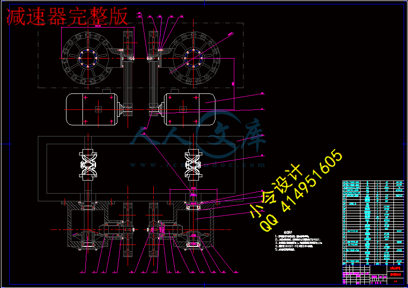
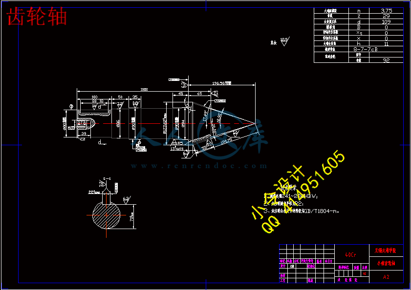
齿轮轴.dwg
齿轮轴.dwg

无轴搅拌机传动系统的设计【7张CAD图纸+毕业论文】【答辩通过】

收藏

压缩包内文档预览:
预览图
编号:437671    类型:共享资源    大小:1.23MB    格式:RAR    上传时间:2015-05-31 上传人:好资料QQ****51605 IP属地:江苏
45
积分
关 键 词:
搅拌机 传动系统 设计
资源描述:

摘 要

   本次毕业设计的题目为无轴搅拌机传动部件的设计。首先对传统的几种常见的搅拌机构进行分析、总结其工作原理及其存在的常见问题。了解目前对其存在的问题的常用解决方案。熟悉“无轴”搅拌理念,掌握无轴搅拌机的工作原理,然后将其与传统的搅拌机进行比较,分析其主要优点及可能存在的问题以及解决方案。

其次,这次设计的重点是对其传动部件的设计计算,我采用的是带轮加锥齿轮的减速机构,即利用了带轮的传动远距离传动、大传动比,又利用了锥齿轮传动可改变传动方向的优点。通过设计计算达到了即提高工作效率又能有效地节约能源的目的。


关键词: 无轴搅拌机 ;传动部件 ;搅拌机构


Abstract

The graduation project is the subject of non-transmission parts mixer shaft design. First of all, the traditional institutions in several common mixing analysis, concluding its work principle and the existence of the frequently asked questions. Understand the current problems of its common solutions. Familiar with the "non-axis" mixing the concept of master-axis mixer without the working principle, and the mixer with the traditional comparison, analysis of their main advantages and potential problems and solutions.

Secondly, this is designed to focus on the design of its drive components, I used the bevel gear pulley increases the speed, namely the use of long-distance transmission of drive pulley, the transmission ratio and the use of a bevel gear transmission can change the direction of the advantages of transmission. Achieved through the design of computing that can effectively improve the efficiency and energy savings.


Key words: No shaft mixer;Transmission parts ;Stir agencies


目 录

摘 要III

AbstractIV

目 录V

1 绪论1

  1.1 无轴式搅拌机研究发展现状1

  1.2 搅拌机的各种类型及特点2

  1.3 无轴式搅拌机特点3

  1.4 搅拌机的分析及设计任务3

    1.4.1 搅拌机常见问题的原因分析3

    1.4.2 无轴搅拌的理念4

    1.4.3 基本设计任务5

    1.4.4 毕业设计的目的5

  1.5 课题研究背景及意义5

    1.5.1 课题研究背景5

    1.5.2 课题研究意义5

2 传动方案及电动机的选择7

  2.1 传动方案的选择7

  2.2 电动机选择8

3 传动比的计算与分配9

  3.1 计算总传动比9

  3.2 传动比的分配9

4 传动运动参数的计算11

  4.1 各级转速11

  4.2 各级的输入功率11

  4.3 各级转矩11

5 V带轮传动的设计计算13

  5.1 设计准则13

  5.2 原始数据及设计内容13

    5.2.1 原始数据:13

    5.2.2 设计内容:13

  5.3 设计步骤和方法13

    5.3.1 确定计算功率13

    5.3.2 选择带型13

    5.3.3 确定带轮的基准直径和13

    5.3.4 确定中心距和带轮的基准长度14

    5.3.5 验算主动轮上的包角14

    5.3.6 单根V带传递的额定功率15

    5.3.7 确定带的根数Z15

    5.3.8 确定带的预紧力15

6 V带轮设计17

  6.1 V带轮的设计内容17

  6.2 设计要求17

  6.3 带轮材料的选择及结构形式17

    6.3.1 材料的选择17

    6.3.2 结构形式17

  6.4 V带轮的轮槽17

  6.5 V带轮传动的张紧18

7 锥齿轮传动的设计计算19

  7.1. 选定精度等级,材料及齿数19

    7.1.1齿轮精度等级的选择19

    7.1.2 材料选择19

    7.1.3 齿数选择19

  7.2 按齿面接触强度设计19

    7.2.1 确定公式内的各计算数值20

    7.2.2 计算20

  7.3 按齿根弯曲强度设计21

    7.3.1 确定公式内的各计算数值21

  7.4 几何尺寸计算22

    7.4.1 计算分度圆直径22

    7.4.2 锥距22

    7.4.3 计算齿轮宽度22

    7.4.4 锥齿轮的结构设计22

8 轴的设计计算25

  8.1 I轴的设计计算(锥齿轮轴)25

    8.1.1 材料25

    8.1.2 初定轴的最小直径25

    8.1.3 根据轴定位的要求确定轴的各段直径和长度25

    8.1.4 小锥齿轮的受力分析26

    8.1.5 键的校核26

    8.1.6 I轴轴承的校核26

    8.1.7 轴上载荷的计算28

    8.1.8 按弯扭合成应力校核轴的强度29

  8.2 II轴的设计计算29

    8.2.1 材料29

    8.2.2 初定最小直径29

    8.2.3 联轴器的选择29

    8.2.4 根据轴的定位要求,确定各段直径和长度30

    8.2.5 大锥齿轮轴的受力分析30

    8.2.6 键的校核30

    8.2.7 轴承的校核30

    8.2.8 轴上载荷的计算32

    8.2.9 按弯扭合成应力校核轴的强度33

9 结论与展望35

致谢37

参考文献39


1 绪论

1.1 无轴式搅拌机研究发展现状

改革开放35年以来,中国混凝土搅拌机市场从无到有、从小到大。目前,我国年产水泥混凝土约为15亿,搅拌机的年产量也居世界前列。相比较而言,我国具有的自主知识产权技术也很少。但随着商品混凝土的大力推广、工程建设施工的高效率化、高质量化和高效益化,推动了混凝土搅拌设备向高效率、高质量的方向不断发展,一些传统设备己经无法满足施工要求。

在现有的搅拌机的基础上,对新型搅拌设备的研究和开发,提高混凝土搅拌机的设计水平,同时带动相关技术的发展,创造一个良好的生产空间;对高效混凝土搅拌机的开发,推动搅拌及机事业性能的快速发展,生产出适应市场要求、具有高可靠性和较强竞争力的搅拌机。依据新的搅拌原理,采用理论探讨和试验分析相结合的办法,能方便解决大型双卧轴搅拌机存在的低效率问题,如果生产工业化成功应用,一定为研制具有自主知识产权的高效搅拌机做出重大贡献。

长期以来,国内外搅拌设备虽然种类很多,但他们的共同特点:有一根轴贯穿整个搅拌空间。“双螺旋轴搅拌机”是一种新型的“无轴”搅拌机,它具有双倍的径向进给料流,双倍的轴向进给料流,双倍的剪切力,使搅拌效率达到普通搅拌机的两倍,能耗更小。“双螺旋轴搅拌机”无水平的主轴,不会产生混凝土黏合中心轴并产生结块形成抱轴的现象,更适合于加工粘性强和添加有纤维的混凝土材料。

20世纪70年代未至80年代初,我国为了适应建筑业有关方面混凝土发展的需要,在引进国外搅拌机的基础上,研制出了10多种混凝土搅拌楼(站)。经过引进研究、自主开发生产等几个阶段,到本世纪初,我国搅拌机技术得到更大的发展,在产品型号和生产数量上,都达到了一定规模,出现了一批更具有自主知识产权的新产品,并开始形成了一个具有一定规模和竞争能力的产业。2006年,我国生产装机容量0.5~6的搅拌站2100多台,已成为搅拌设备的研究和生产大国。

自上世纪八十年代初已经开始研制JS系列双卧轴混凝土搅拌机,一直到现在,已研制出从JS35~JS6000系列搅拌机,一直处于国际领先水平,尤其从2000年开始采用UG等三维软件,对搅拌机研究进行优化设计,对搅拌设备进行了动力分析和受力分析,大大提高产品的可靠性,达到国际先进水平。这些搅拌机的研制,基本满足了我国混凝土发展的需求,但随着主机市场的不断发展,新型主机的需求越来越多。无轴式搅拌机在国外也处在研究发展阶段。


1.2搅拌机的各种类型及特点

目前使用的搅拌机就其原理而言,其基本上可分为自落式和强制式两大类。

自落式搅拌机有较长的历史,早在20世纪初,混凝土搅拌设备开始不断出现。50年代后,人们研发出反转出料式和倾翻出料式的双锥形搅拌机,同时,其他一些搅拌机,如裂筒式搅拌机等相继问世。运作时,拌筒绕着水平轴线旋转,加入搅拌筒内的物料,叶片将物料提升至一定高度,然后借助自重下落,这样不断的循环运动,达到搅拌的理想效果。自落式混凝土搅拌机的结构简单,一般以搅拌塑性混凝土为主。但自落式搅拌机已不符合国家的有关标准,属于淘汰产品,所以本文不作研究。

强制式搅拌机从20世纪50年代初兴起后,得到了迅速的发展和生产推广。最先出现的是圆盘立轴式强制混凝土搅拌机。这种搅拌机分为涡桨式和行星式两种。19世纪70年代后,随着轻骨料的出现,研制出了圆槽卧轴式强制搅拌机。

实践证明,在上述混凝土搅拌设备的搅拌主机在工作中经常出现混凝土 “抱轴”现象。如果不及时停机清除,“抱轴”的混凝土会越来越多,将会引发搅拌机电机因过载而堵转,造成电机烧毁。

1.3无轴式搅拌机特点

无轴式搅拌机与以上所述的各种卧轴式搅拌机相比有以下一些优点:

(1)解决了搅拌机运作中普遍存在的抱轴现象;

(2)减小了因搅拌臂的重量产生的大量弯矩;

(3)解决了因搅拌臂的安装而产生的偏心力,缓解了对轴端的冲击;

(4)搅拌机上安装搅的拌臂和连接套数量大,占用搅拌筒的空间大,减少了筒内的有效容积,无轴搅拌机搅拌装置结构简单,构思灵活,有效提高了搅拌筒的搅拌容积;

(5)无轴式搅拌机不需搅拌臂的更换,维修也方便,大大降低了工人的工作量;

(6)减少了由于抱轴引起的冲洗次数,节约用水量,同时也减少了对环境的污染,成本得到降低;

1.4 搅拌机的分析及设计任务                                    

 1.4.1 搅拌机常见问题的原因分析

   实际工作中,搅拌机的搅拌主体在工作中经常出现混凝土“抱轴”现象。如果不及时停机清除,“抱轴”的混凝土会越来越多,将会引起电机过载而发生堵转,造成电机烧毁或产生破坏。

经过调查和研究,普遍赞同搅拌机 “抱轴”产生的原因是可以避免的,原因可以分为两大类:设计不当和使用不规范。表现形式如下:

(1) 投料设备设计的不合理。比如物料和进水口位置及方向设计不合理,导致轴上堆积大量物料,粘结在轴上的物料卡住转轴;

(2)进水口方向和冲洗方向不得当,另外冲水压力过低也是原因之一。冲洗搅拌筒时,搅拌器上粘着的大量物料清理不掉;

(3) 搅拌筒的容积存在不合理利用率,容积利用率太小,搅拌时,搅拌轴在混凝土上面,粘附在上面的物料得不到搅拌,从而慢慢凝固,阻碍轴的转动;

  (4)操作人员在设备搅拌卸料后,没有及时清理搅拌罐,同时搅拌轴上残留的混凝土发生凝固,搅拌轴的表面上残留粗糙不平的物料,干燥后凝固在轴上,以后就会越聚越多影响搅拌轴转动。

 1.4.2 无轴搅拌的理念

长期以来,国内外搅拌机虽难种类繁多,但他们的共同特点就是有一跟轴贯穿整个搅拌空间。


“双螺旋轴搅拌机”是一种新型的“无轴”搅拌机,其叶片形状如图1.1所示。它具有双倍的径向物料流,双倍的轴向物料流,双倍的剪切力,使搅拌效率是普通搅拌机两倍多,能耗更小。“双螺旋轴搅拌机”无水平的主轴,不会产生混凝土骨料黏合中心轴上结块形成抱轴现象,利于加工粘性较强和添加有纤维的特种混凝土材料。无搅拌臂的阻碍,使其空间更大。

但是仅对其搅拌部分进行的改进还是不能达到真正的提高效率、节约能源的效果,所以这次我们在对一些公司、工厂进行调研后,对其传动部件进行深入研究确定了最初方案,对机器进行改良,并达到理想效果。

1.4.3 基本设计任务

毕业设计的主要任务主要有:

1、拟定传动方案;

2、对减速器进行设计计算;

3、绘制搅拌机装配部件装配总图一份和组要零件图六份;

4、按指定格式和要求撰写毕业设计计算说明书。

 1.4.4 毕业设计的目的

毕业设计是对学生进行工程师基本训练的重要环节,通过毕业设计能达到以下目的:

   (1)巩固、熟悉并综合运用所学的知识;

(2)培养理论联系实际的学风;

(3)熟悉进行机械设计的一般步骤和常见问题,掌握机械设计的一般技巧;

(4)学会查阅运用技术资料;初步掌握对专业范围内的生产技术问题进行研究的能力。


内容简介:
无锡太湖学院 信 机 系 机械工程及自动化 专业一、 题目及专题1、 题目 无轴搅拌机传动系统的设计 2、 专题 二、 课题来源及选题依据参考现场实际生产,要求学生能够结合无轴搅拌机的工作原理和过程,针对实际使用过程中存在的搅拌阻力、搅拌空间、能耗等问题,综合所学的机械原理、机械设计以及机电传动等知识,对搅拌机的无轴工作进行改进设计,使其在工作过程中真正达到提高效率,节约能源的效果。 改进过程中,在满足产品工作要求的情况下,应尽可能多的采用标准件,提高其互换性要求,以减少产品的设计生产成本。 三、 本设计(论文或其他)应达到的要求1、 该部件工作时,能运转正常;2、 熟悉有关标准、规格、手册和资料的应用; 3、 拟定工作机构和传动系统的运动方案,并进行多方案对 分析;4、 对无轴搅拌机传动系统具有初步分析能力和改进设计的能 力; 5、 理论联系实际的工作方法和独立工作能力深化和提高; 6、设计绘制零件工作图若干; 7、编制设计说明书1份。 四、 接受任务学生: 机械97 班 姓名 龙跃 五、 开始及完成日期:自2012年11月12日至2013年5月25日六、 设计(论文)指导(或顾问): 指导教师 签名 签名 签名 教研室主任 科学组组长 签名 系主任 签名 2012年11月12日I英文原文:Designing and Modeling a Torque and Speed Control Transmission (TSCT)1 Background The Partnership for a New Generation of Vehicles (PNGV) was formed between the Federal Government, Ford Motor Company, General Motors Corporation, and Chrysler Corporation. The goal of this partnership was to allow the major U.S. automotive manufactures to collaborate with each other and produce high fuelefficiency, low emissions vehicles for sale to the general public. The performance objective for these manufacturers was to create mid-sized passenger cars capable of attaining an 80 mpg (gasoline) composite fuel economy rating on the Environmental Protection Agency (EPA) city and highway cycles. Hybrid vehicle technology has shown great promise in attaining the goals set forth by the PNGV. Hybrid electric vehicles (HEVs) employ technology that helps bridge the gap between the future hope of an electric vehicle (EV) and todays current vehicles. Within the past year hybrid electric vehicles have gained an important place in the vehicle market. American Honda Motor Company, Inc. is currently releasing their first generation HEV, the Insight. The Insight is a compact, two passenger, parallel HEV which achieves more than 65 mpg (composite) on the EPA test cycles: the highest of any production vehicle ever tested. Toyota Motor Corporation has also released a hybrid vehicle for sale to the general public. The Toyota Prius is currently for sale in Japan and will come the United States in the beginning of the year 2000. The Prius is a four passenger combination hybrid employing an a gasoline engine, high power electric motor, and an electromechanical continuously variable transmission (CVT) comprised of a planetary geartrain and a high power alternator/motor. It is through technology incorporated in vehicles such as the Prius that automotive transmission design and operation will make significant new advances. 1.1 Current Automotive Transmission Technologies With the advent of the automobile also came the creation of the automotive transmission. Early vehicles were simple with manual controls for all functions including the transmission. As advances have been made in vehicles over the past several decades, transmission technology has also advanced. The automatic transmission has nearly replaced the manual transmission in all but economy and performance cars. This trend can be attributed to ease of use, higher power engines becoming available, and congestion in urban areas. Another new transmission technology beginning to see application particularly in foreign markets is the continuously variable transmission that offers continuous operation without shifting between a high and low gear ratio. These three types of transmissions are all similar in function though their objectives are accomplished in different ways. The capabilities of these transmissions are limited to decoupling the engine speed from the speed of wheels and thereby providing one of several forward or reverse gear ratios. Each transmission is also a single input (engine) and single output (drive device). There are typically no provisions for attaching multiple power sources or for extracting power from more than one point. The exception to this is heavy-duty transmissions equipped with provisions for a power take off for driving auxiliary mechanical equipment. Single input, single output operation limits drivetrain flexibility for newer systems employing multiple power sources such as those used in the next generation of hybrid vehicles. 1.1.1 Manual Transmission Operation Manual transmissions are the least complex and oldest design of power transmission available. In simplest form, a manual transmission is a linear combination of a clutch and a directly geared connection. More sophisticated examples rely on this design but add the ability to select other gear ratios to allow different output speeds for the same input speed. Of these types of transmissions, there are two variations: synchronized and unsynchronized. Synchronized manual transmissions are typically used for light duty applications. Coupled to each gear is a synchronizer that allows the operator to disengage the clutch and select whatever gear necessary. The selection of a different gear engages the synchronizer, which then matches engine input speed and transmission output speed before the gears are engaged. Unsynchronized manual transmissions are more robust by nature. The operator must double-clutch between shifts to match engine and transmission speed manually. However, this allows a transmission of a given size to handle greater load as space previously occupied by the synchronizers can now be dedicated to the use of wider gears. Applications of these types of manual transmissions are for over-the-road trucks and up to larger equipment with total vehicle weights over 100 tons. 1 1.1.2 Automatic Transmission Operation Automatic transmissions are a complex assembly of many components that allow for seamless power transmission. Those currently available in production vehicles use torque converters, clutches, and planetary gear sets for the selection of different output ratios. The engine is connected to the torque converter that acts very much like a clutch under some conditions while more like a direct connection in others. The torque converter is a hydraulic coupling that will slip under light load (idle), but engage progressively under higher load. While the torque converter transmits power to the transmission there is a speed reduction across the unit during low speed operation. This reduction is typically between 2.5:1 to 3.5:1. Once higher vehicle speeds are attained, the torque converter input and output may be locked together to achieve a direct drive though the unit. The output of the torque converter is typically connected to a hydraulic pump that provides the necessary pressure to engage different clutches within the transmission and the planetary drive. Different gear ratios are created through the use of two or more planetary gearsets. These gearsets are combined with clutches on different elements. By clutching and declutching different elements, multiple gear ratios are possible. Basic automatic transmissions are equipped with a single control input that is throttle position. The combination of this with the hydraulic pressure created within the transmission allows for mechanical open loop control of all gear selections. Newer variations of the automatic transmission are equipped with electronic feedback controls. Shift logic is dependent on many more variables such as engine speed, temperature, current driving trend, throttle position, vehicle accelerations, etc. This allows the transmission controller to monitor vehicle operation and using a rule-based control strategy decide which gear is best suited to the current driving conditions. Newer systems are also integrated with the engine controller such that a vehicle control computer has authority over engine and transmission operation simultaneously. This allows for such features as increasing engine speed during high-speed downshifts to match engine and transmission speed for smoother shifting and retarding fueling and ignition timing during high power upshifts to reduce jerk. Previously, transmissioncontrol was much simpler because overrunning clutches were employed in higher gears that only allowed for coasting to conserve fuel. 1 1.1.3 Continuously Variable Transmission Operation Continuously variable transmissions are one of the emerging transmission technologies of the last twenty years. This type of transmission allows power transmission over a given range of operation with infinitely variable gear ratios between a high and low extreme. These transmissions are constructed using two variable diameter pulleys with a belt connecting the two. As one pulley increases in size, the other decreases. This is accomplished by locating on one shaft a stationary sheave and a movable sheave. For automotive applications, a hydraulic actuator controls movement of the sheave. However, centrifugal systems along with high power electronic solenoids may be used. A second shaft in the CVT contains the other stationary sheave and movable sheave also controlled hydraulically. A flexible metal belt is fitted around these two pulleys and the movable sheaves are located on opposite sides of the belt. There are two variations of this type of transmission: push belt and pull belt. Pull belt CVTs were the first type to be manufactured due to simplicity. A clutch is attached between the first pulley and the engine while the output of the second pulley was connected to a differential and thus the wheels. A hydraulic pump is used to control the diameter of the two different pulleys. As power is applied the first pulley creates a torque that is transmitted through the belt (under tension) to the second pulley. Control of the transmission ratio is usually a direct relationship dependent upon throttle position. Push belt CVTs, similar in design to the Van Doorne, are much the same as pull belt CVTs, except that power is transmitted through the belt while under compression. This provides a higher overall efficiency due to the belt being pushed out of the second pulley and lowering frictional losses. Current work with these transmissions is being focused on creating larger units capable of handling more torque. Efficiency of the CVT is directly related to how much tension is in the belt between the two pulleys. CVT torque handling capacity increases as tension in the belt increases. However, this increased tension lowers power transmission efficiency. The belt must slide across the faces of each pulley as it enters and exits upon each half rotation. This sliding of the belt creates frictional losses within the system. In addition, there may be significant parasitic losses associated with raising the hydraulic pressure required to move or maintain the position of the sheaves in each pulley. 2 1.1.4 Automatically Shifted Manual Transmission Operation Automatically shifted manual transmissions are a fairly recent innovation. The benefit of the manual transmission is that (due to the direct mechanical connection through fixed gears) efficiency is very high. The drawback is that there must be some interaction with the user in the selection and changing of gears. Automatically shifted manuals were created to address this issue. These types of transmissions are traditionally synchronized manual transmissions with the addition of automation of the gear selection and control of the clutch. A logic controller is also employed to decide when and how to shift. Automatic shifting is usually accomplished through the use of electro-hydraulics. A high-pressure electric pump supplies pressure to hydraulic solenoids that are used to shift the transmission. A hydraulic ram is also used to engage and disengage the clutch. Current versions of these transmissions also employ unsynchronized gears. This allows for overall smaller packaging to accomplish the same task. Input speed of the engine is monitored along with layshaft speed. When a gear change is initiated, the controller opens the clutch, shifts to the desired gear while matching engine and lay shaft speed, and then closes the clutch again. This shifting operation can all be achieved in less than one third of a second. Automatically shifted manual transmissions shift gears faster than humanly possible. 3 1.1.5 Manually Shifted Automatic Transmission Operation Manually shifted automatic transmissions are a variation on control of the transmission. The user is allowed to select either automatic or manual shifting modes. During automatic mode, the transmission functions identically to an automatic transmission. While in manual shift mode however, the transmission controller allows the user full authority over gear changes as long as the gear change will not overspeed the engine. This mode of operation traditionally offers the user tighter, more positive shift feel. The only requirement of an automatic transmission for manual shifting is that shifts must be accomplished rapidly enough to allow the user a feeling of fluidity. The act of shifting must provide the immediate desired response. 3 1.1.6 Planetary Gear Drive Transmission Operation Planetary gear sets are unique in that the combination of gears creates a twodegree-of-freedom system. The gear sets are comprised of a ring gear, a sun gear in the center, and planetary gears that contact both the ring and the sun gears. Motion of the planetary gears is controlled by the carrier on which each of the planetary gears rotate. The carrier maintains the position of the planets in relation to each other but allows rotation of all planets freely. Inputs (or outputs) to the gear train are the ring gear, sun gear, and planetary carrier. By prescribing the motion of any two of these parameters, the third is fixed in relation to the other two. By employing one planetary geartrain, a fixed ratio between input and output is created. Increasing or decreasing the number of teeth on the sun and ring gears can change this ratio. This in turn changes the number of teeth on the planetary gears, which has no other effect as these gears act as idlers. When combining more than one planetary gear train at one time, braking or allowing the movement of different elements can create a wide range of effective operation in terms of relative speeds, torque transfer, and direction of rotation. This is the type of system that is used in automatic transmissions described above. These systems are also employed in large stationary power transmission applications. 1 1.2 Current Hybrid Electric Vehicle Transmission Design Hybrid vehicles are vehicles that utilize more than one power source. Current propulsion technologies being favored are compression ignition (CI) engines, spark ignition(SI) engines, hydrogen-fueled engines, fuel cells, gas turbines, and high power electric drives. Energy storage devices include batteries, ultra-capacitors, and flywheels. Hybrid powertrains can be any combinations of these technologies. The aim of these vehicles is to use cutting edge technology combined with current mass-produced components to achieve much higher fuel economy combined with lower emissions without raising consumer costs appreciably. These vehicles are targeted to bridge the gap between current technology and the future hope of a Zero Emission Vehicle (ZEV), presumably a hydrogen-fueled fuel cell vehicle. The operation of these systems must also be transparent to the user to enhance consumer acceptability and the vehicle must still maintain all required safety features with comparable dynamic performance all at an acceptable cost. By combining multiple power sources, overall vehicle efficiency can be improved by the ability to choose the most efficient power source during the given operating conditions. This is key in improving vehicle efficiency because current battery technology dictates that nearly all total energy used by the vehicle across a reasonable range of driving comes from the on-board fuel. Highly adaptive control strategies that may be employed in the next generation of HEVs may monitor vehicle speed, desired torque, energy available, and recent operating history to choose which mode of operation is most beneficial. These advanced control schemes will maximize the usage of the fuel energy available by choosing the most efficient means of power delivery at any instant. The reduced usage of energy for a given amount of work may also result in lower exhaust emissions due to a reduction in fuel energy used. 1.2.1 The Advantages and Disadvantages of Series Hybrid Vehicles Series hybrid vehicles typically have an internal combustion engine (ICE) that iscoupled directly to an electric alternator. The vehicle final drive is supplied entirely by an electric traction motor that is supplied energy by the battery pack or combination of engine and alternator. The benefit of this type of operation is the engine speed and torque are decoupled from the instantaneous vehicle load and the engine needs only to run when battery state of charge (SoC) has dropped below some lower level. This allows engine operation to be optimized for both fueling and ignition timing in the case of a spark ignited engine, or fueling and injection timing for a compression ignition engine. The engine is also operated in the most efficient speed and torque without encountering transient operation regardless of load. The result is excellent fuel economy and low emissions. Series HEV operation is exceptionally well suited to highly transient vehicle operation which is prevalent in highly urban areas and city driving. The disadvantage to series hybrid operation is the efficiency losses associated with converting mechanical to electrical and then electrical to mechanical energy. Further losses in system efficiency are realized when the energy is stored in the battery pack for later use. Only a fraction of the energy put into the batteries can be returned due to the internal resistance of the batteries. The mechanical energy of the engine is directly converted to electricity by an alternator that has losses both in internal resistance and eddy currents present. Further losses are incurred when this electrical energy is converted back to mechanical energy by the traction motor and controller. Dynamic performance is also limited, as the engine cannot supplement the traction motor in powering the vehicle. 1.2.2 The Advantages and Disadvantages of Parallel Hybrid Vehicles Parallel systems also employ two power sources, typically an engine and a traction motor with both directly coupled to the wheels typically through a multi-speed transmission. This requires that the engine see substantial transient operation. However, the motor can act as a load-leveling device allowing the engine to operate in a more efficient operating region. When the vehicle is operating in a low load state the engine can be decoupled from the drivetrain and shut off, or the motor can be used to charge while driving creating a greater power demand for the engine and storing energy in the battery pack. The disadvantage of parallel hybrids is that direct connection of the engine to the wheels requires transient engine operation. This operation lowers fuel economy and increases exhaust emissions especially when employing SI engines. Ignition timing and fueling cannot be optimized for a single region of operation either. However, dynamic performance of parallel hybrids is much better than that of series hybrids using the same components. Much more power is available as both the engine and motor can provide power to the wheels simultaneously. These characteristics lend parallel HEVs to excel in higher load, less transient situations and when using high efficiency engines such as CI engines. 1.2.3 The Advantages and Disadvantages of Combination Hybrid Vehicles The third variation of hybrid vehicle drivetrains is the combination, which is a system that can function both as a series and parallel hybrid. Complex combinations of engines, alternators, and motors can accomplish this with geared connections and multiple clutches. By clutching and declutching different elements, a combination can be designed to function as a series hybrid under low speed transient conditions and then as a parallel hybrid under higher speed and load. This allows for increased efficiency as each mode of operation is employed under the ideal operating conditions. Drawbacks to these systems are increased mechanical and drivetrain control complexity along with higher weight associated with more components. Controlling these types of systems is much more difficult than either a series or parallel HEV. The system must first be capable of operating as a series or parallel and then be able to choose which mode is optimum and switch between the two seamlessly during vehicle operation. 1.3 Combining Two Different Types of Transmissions All current automotive transmissions in production are single input, single output meaning that one power source is connected to the wheels. This design is acceptable for most situations, but to achieve the highest possible efficiency in a hybrid vehicle it would be beneficial to combine different types of transmissions. Under different conditions some transmissions are more efficient than others are. By using multipletransmissions, it is possible to combine each in a way that the area of operation for each transmission is moved toward a more efficient region than normally possible. This combination of multiple transmissions can also provide the ability to connect more than one power source and have more than one output.1.4 Multiple Transmission Combinations for Hybrid Vehicle Applications Hybrid vehicles posses more than one power source such as an engine and one or more motors. These sources can be distinctly different from each other in operating speed, power output, and control strategy. When combining multiple power source inputs into a single transmission, operation is limited by creating a transmission that cannot be optimized for either. By utilizing a combination of transmissions with a combination of power sources, the transmission for each source can be optimized for the desired area of operation increasing overall system efficiency. The total system can be tailored to couple the most efficient means of power with the most efficient way to channel the power to the wheels. 1.5 Objectives West Virginia University is proposing the design of the Torque and Speed Control Transmission (TSCT), a multiple input, multiple output transmission. This design will allow for much more freedom in powertrain configurations. Multiple power sources may be connected to the TSCT and power can be removed from the transmission either by a motor (acting as a alternator), an alternator, or the drive wheels of the vehicle. This transmission design also will employ a CVT and a planetary geartrain. The combination of these two transmission types allows for six distinct modes of operation. These modes are Conventional Vehicle, Electric Vehicle, Series HEV, Parallel HEV variate 1, Parallel HEV variate 2, and a Geared Neutral mode. The purpose of this study is to determine the feasibility of such a transmission. Several of the possible combinations will be analyzed and the most beneficial design will be reviewed further in depth.2 Literature Review Automotive manufacturers and private companies alike have created alternative transmission designs as a means to achieve greater fuel economy and lower vehicle emissions. A brief review of those transmissions and powertrains that are similar in design and operation to the TSCT follows.Results of the ETH Hybrid III-Vehicle Project The ETH-Hybrid III is a parallel hybrid drivetrain built by the Swiss Federal Institute of Technology. The ETH-Hybrid III drivetrain incorporates a spark ignited internal combustion engine, an asynchronous electric motor, a flywheel, a continuously variable transmission, and a battery pack. Under light load conditions, the electric motor is used to power the vehicle with the flywheel providing power for peak power demands through the CVT. As energy is lost from the flywheel, the engine is started and operated at full load for a short time to recharge the flywheel. Under moderate and high load conditions, the engine powers the vehicle with the flywheel acting as a load-leveling device. Engine operation is moved to a more efficient regime by selecting the proper ratio across the CVT operating range. A regenerative braking mode is also possible with the motor recharging the batteries or the energy being imparted into the flywheel. When these two storage devices are at full capacity, a latent heat energy storage device converts the energy to raise the operating temperature of the oil and coolant. However, it is unclear what real benefit is gained from adding heat to the lubrication and cooling systems other than to reduce cold or warm start emissions. Furthermore, the use of flywheels has not been proven as an effective or efficient means of energy storage. 4A Charge Sustaining Parallel HEV Application of the Transmotor The transmotor was developed by Texas A&M University. Operation of thetransmotor is characterized as an electromechanical CVT with three degrees of freedom: input, output, and an electronic connection. The transmotor is an electric motor with the input shaft connected to the stator and the output shaft connected to the rotor. This allows the transmotor to function in the place of a mechanical transmission. To accomplish speed reduction relative to the input speed, electric energy is extracted from the motor. Direct drive through the transmotor is possible by shorting the leads of the motor together and a speed increase across the transmotor is accomplished by consuming electric energy. Combination HEV operation can be achieved by employing the transmotor in conjunction with another electric motor. By combining the transmotor in series between an engine and an electric motor, operation of the engine can occur at a constant speed and torque during transient conditions. This combination of the transmotor in conjunction with another motor also requires more complex control. Also, to achieve an given speed ratio, power must always be flowing in the transmotor system. This can lead to a loss in efficiency due to the resistance and inefficiencies of the electrical components involved. 5Functional Design of a Motor Integrated CVT for a Parallel HEV Nissan ParallelHEV Nissan Motor Company has created a parallel, charge sustaining HEV. Basic components of the system are a high power four cylinder spark ignited engine, electronically engaged clutch, low power electric motor, and a continuously variable transmission. This drivetrain is capable of three main modes of operation: conventional vehicle, electric vehicle, and charge while driving. For conventional vehicle operation, the clutch is engaged and power from the engine is sent through the CVT to the wheels. In electric only operation, EV or ZEV, the clutch between the engine and motor is opened and power from the motor is transmitted to the wheels through the CVT. For parallel HEV operation, the clutch is closed between the engine and motor and all power is sent through the CVT. Under lighter load conditions the motor can act as a load leveling device and create higher load on the engine by charging the batteries. The advantages of this system are simplicity and CVT operation allows for the engine to operate in more efficient regimes than possible with an automatic or manualtransmission. However, power from the electric motor must be sent through the CVT during pure electric operation incurring high efficiency losses unnecessarily. The motor could be placed downstream of the transmission taking advantage of the inherent high torque characteristics of the motor. 6中文译文:设计与塑造转矩和速度控制变速器( TSCT )1背景新一代的(PNGV)车的合作在联邦政府、福特公司,通用汽车公司和克莱斯勒公司之间被结成了。 这次合作的目标是让美国各大汽车制造商互相协作和生产高油耗效率,低排放车辆出售给普通公众。表现这些制造商的宗旨将创造中型的客车能够获得在环境保护代办处(EPA)城市和高速公路周期的一个80 英里 (汽油)综合燃料经济规定值。混合动力汽车技术已经表现出极大的承诺,以实现由PNGV规定的目标。混合动力电动汽车(混合电动汽车)采用的技术,可以帮助弥补今天和未来当前车之间的差距。在过去的一年里混合动力电动汽车已获得在汽车市场中占有重要位置。美国本田汽车公司,公司目前正在推出的第一代混合动力汽车,有敏锐的洞察力。敏锐的洞察力是一种紧凑,可坐两名乘客,其中混合动力汽车实现并行超过在美国环保局的测试周期65英里(综合):任何生产车辆进行最高测试。丰田汽车公司也推出了混合动力汽车出售给普通公众。丰田普锐斯目前在日本销售,并将于2000年初在美国销售。普瑞斯是四个客运组合 混合使用的汽油发动机,大功率电动机,以及电机连续可变传动(无级变速器)组成的行星geartrain和高功率交流发电机/电动机。正是通过合并的技术,如普锐斯的汽车变速器设计和运行将取得重大新进展。 1.1目前的汽车变速器技术随着汽车的出现也建立了汽车传输。早期车辆简单,所有功能的手动控制包括传输。由于已经取得进展的车辆,在过去几十年来,传输技术也先进。但在所有经济和高性能汽车,自动传输几乎取代了手动变速箱。这一趋势可以归结于它的易用性,高功率的引擎成为可利用在拥挤的城市地区。另一种新的传输技术的应用开始尤其是在国外市场是连续可变传动,提供持续运作不转移之间的高,低传动比。这三种类型的传输都是相似的功能但其目标是完成以不同的方式。这些传输的能力被限制到分离从轮子的速度的发动机速度和从而提供几个向前或换向齿轮比率之一。每个传输也是一个单输入(引擎)和单输出(驱动装置) 。通常没有规定附加多个电源或用于提取从力量超过一点。此规则的例外情况是重型变速箱配备规定的力量是为驾驶辅助机械设备。单输入,单输出操作的灵活性,限制新的动力系统采用多种电源,如所使用的新一代混合动力汽车。 1.1.1手动变速箱操作手动变速箱是由最复杂和最古老的设计功率传输提供。在最简单的形式中,一个手动变速箱是一个线性组合离合器和直接面向连接。更复杂的例子依靠这种设计,但增加能力,选择其他传动比,使不同的输出速度和同样的输入速度。这些类型的传输,有两个变化:同步和不同步的。同步手动变速箱通常用于轻型应用。加上每个齿轮是同步,可让操作者脱离接触离合器和选择什么齿轮必要。选择不同的齿轮进行了同步器,然后匹配引擎输入速度和输出速度传输在齿轮接合之前。同步手动变速箱有更强劲的性质。操作员必须在双离合器之间的转变中,以配合发动机和传输速度手动。 然而,这使得同步器以前被占领的空间能允许特定大小的传输,处理更大的负荷,现在可以更专注于广泛的使用齿轮。应用这些类型的手动变速箱是超道卡车和大型设备最多的总车辆重量超过100吨。 1 1.1.2自动变速器操作自动变速器是一个复杂的装配,有许多组成部分,使无缝输电。目前可在生产的车辆中使用液力变矩器,离合器,和行星齿轮组的选择不同的输出比例。发动机是连接到液力变矩器的行为很象是离合器,而在某些情况下更像是直接连接在其他上。液力变矩器和液力偶合器是将轻负载下支路(空闲) ,但从事高负荷下逐步。虽然变矩器传递功率的传输速度是减少整个单位在低速运行。这种减少通常是2.5:1到3.5:1之间。一旦有更高的车速达到,液力变矩器输入和输出可锁定在一起,实现直接驱动传动。液力变矩器通常是连接到液压泵产出的,提供必要的压力,从事不同的离合器的传动和行星传动。不同的变速比创建通过使用两个或两个以上的行星gearsets 。这些gearsets相结合离合器的不同要素。由不同要素抓住和脱开离合器,多传动比是可能的。自动变速器基本都配备了一个单一的控制装备节气门位置。这与水压内设立传输允许机械开环控制所有设备的选择的结合,。更新不同的自动变速器都配有电子反馈控制。转向逻辑取决于许多变数,如发动机转速,温度, 电流驱动的趋势,节气门位置,车辆加速度,等这使得传输控制器,以监测车辆运行和使用以规则为基础的控制战略决定哪个齿轮最适合当前的行车条件。更新系统还集成了引擎控制器,例如,一个汽车控制计算机有权力让发动机和变速箱操作同时进行。这些特点可以增加发动机转速在高速上减速传动以匹配引擎和传输速度的平滑转移和延缓推动和点火正时在高功率加速减少反射 。此前,传输控制简单得多,因为超越离合器使用了较高的齿轮,只有允许滑行,以节约燃料。 1 1.1.3变速运行在过去的二十年,连续可变变速箱是一种新兴的传播技术。这种类型的传输,可提供电源给传输特定业务范围的无限可变传动比之间的高,低极端。这些传输采用两个可变直径滑轮用皮带连接。当一个滑轮在大小上增加,其他减少。这是通过定位在一个轴固定轮和一个可移动的滑轮。就汽车应用而言,一个液动执行机构控制滑车轮的运动。然而,离心系统以及高功率电子电磁铁可使用。第二个轴的无级变速器包含其他固定滑轮和滑动轮也控制液压。一个灵活的金属带围绕这些装有两个滑轮和滑动轮,位于两侧的安全带。有两种变异的这种类型的传输:推带和拉带。 拉带无级变速器是第一类 由于制造简单。传动器是附有在第一个滑轮和引擎之间,而第二轮被连接到一个差别和车轮之间。液压泵是用来控制直径的两种不同的滑轮。电源适用于第一轮是通过皮带(张力)第二轮产生了扭矩。控制的传动比通常有直接的关系取决于节气门位置。推带无级变速器 ,在类似的设计上和拉带无级变速器是大致相同 ,但动力是通过带同时压缩。这提供了一个更高的整体效率是由于第二轮带被挤出和摩擦损失降低。目前的工作与这些传输正集中在创造较大单位上能够处理更大的扭矩。无级变速器的效率,直接关系到滑轮皮带之间的张紧。当传送带的紧张力增加,无级变速器扭矩处理量增加。 然而,这增加的紧张力降低输电效率。带必须必须横跨每个滑轮的面上滑动自转。这传送带在系统之内的产生摩擦损失。此外,还有可能有很大的损失与提高液压需要采取或维持的立场,在每个滑轮上。 2 1.1.4自动转为手动变速箱运行自动转为手动变速箱是一个相当新的创新。那个受益的手动变速箱是(由于通过固定齿直接的机械连接轮)的效率是非常高的。缺点是必须有与用户的一些互作用选择和改变的齿轮。 自动转向手册的建立是为了解决这一问题。这些类型的传输传统同步手动变速箱,增加了自动化的设备选择和离合器的控制。逻辑控制器还用来决定何时转变和如何转变。自动转移通常是通过使用电液压。一个高压电泵供应压力 ,液压电磁铁用于转移传播。液压内存也被用来从事和脱离接触离合器。当前版本的这些变速器还采用了同步齿轮。这使得总体规模较小的包装,以完成相同的任务。输入速度的引擎是监测位置轴速度。当换挡发起,控制器打开离合器,同时转向所需的设备的匹配引擎和位置轴速度,然后再次关闭离合器。这个转变操作都可以达到三分之一秒。从人的角度自动转为手动变速箱换档速度比人快速。 3 1.1.5手动操作转向自动变速器手动转向自动变速器是一个变化的控制传输。用户可以选择自动或手动转换模式。 在自动模式下,相同的传输功能的自动传输。而在手动模式的转变中,传输控制器在允许时,用户使用变速杆只要换挡发动机不会超速。这种传统的运作模式给用户提供了更严格,更积极的变化的感觉。唯一的要求是自动变速箱手动转移是必须迅速完成的变化,足以让使用者感到流动性。转移的行为,必须立即提供所需的反应。 3 1.1.6行星齿轮传动传输操作行星齿轮组的独特之处是,结合两个齿轮创造了自由度系统。齿轮集合与圆环和中心齿轮联系在中心的包括一个冕状齿轮、一个中心齿轮和行星。 行星的行动是由其中每一个行星转动的载体控制的。载体关于彼此坚守行星的阵地,但是自由地允许所有行星的自转。 对传动机构的输入是冕状齿轮,太阳齿轮和行星载体。通过规定任何两个参数, 第三相对于其他两个是固定的。采用一个行星轮系,一个固定比例投入和产出之间产生。增加或减少太阳和环形齿轮的牙的数量可以改变这一比例。这反过来又改变了一些行星齿轮的牙,它没有任何其他作用,因为这些齿轮作为无用。在同一时间当结合多个行星传动机构,制动或让流动的不同要素可以建立一个广泛的有效行动范围中相对速度,扭矩转移,及转动方向。这是该类型的系统,用于自动变速器上文所述。这些系统还采用大型固定输电应用。 1 1.2目前的混合动力电动汽车传动设计混合动力汽车的车辆,利用一个以上的电源。当前的推进技术,被看好是压燃式( CI )的引擎,火花点火( SI )的发动机,氢燃料发动机,燃料
温馨提示:
1: 本站所有资源如无特殊说明,都需要本地电脑安装OFFICE2007和PDF阅读器。图纸软件为CAD,CAXA,PROE,UG,SolidWorks等.压缩文件请下载最新的WinRAR软件解压。
2: 本站的文档不包含任何第三方提供的附件图纸等,如果需要附件,请联系上传者。文件的所有权益归上传用户所有。
3.本站RAR压缩包中若带图纸,网页内容里面会有图纸预览,若没有图纸预览就没有图纸。
4. 未经权益所有人同意不得将文件中的内容挪作商业或盈利用途。
5. 人人文库网仅提供信息存储空间,仅对用户上传内容的表现方式做保护处理,对用户上传分享的文档内容本身不做任何修改或编辑,并不能对任何下载内容负责。
6. 下载文件中如有侵权或不适当内容,请与我们联系,我们立即纠正。
7. 本站不保证下载资源的准确性、安全性和完整性, 同时也不承担用户因使用这些下载资源对自己和他人造成任何形式的伤害或损失。
提示  人人文库网所有资源均是用户自行上传分享,仅供网友学习交流,未经上传用户书面授权,请勿作他用。
关于本文
本文标题:无轴搅拌机传动系统的设计【7张CAD图纸+毕业论文】【答辩通过】
链接地址:https://www.renrendoc.com/p-437671.html

官方联系方式

2:不支持迅雷下载,请使用浏览器下载   
3:不支持QQ浏览器下载,请用其他浏览器   
4:下载后的文档和图纸-无水印   
5:文档经过压缩,下载后原文更清晰   
关于我们 - 网站声明 - 网站地图 - 资源地图 - 友情链接 - 网站客服 - 联系我们

网站客服QQ:2881952447     

copyright@ 2020-2025  renrendoc.com 人人文库版权所有   联系电话:400-852-1180

备案号:蜀ICP备2022000484号-2       经营许可证: 川B2-20220663       公网安备川公网安备: 51019002004831号

本站为文档C2C交易模式,即用户上传的文档直接被用户下载,本站只是中间服务平台,本站所有文档下载所得的收益归上传人(含作者)所有。人人文库网仅提供信息存储空间,仅对用户上传内容的表现方式做保护处理,对上载内容本身不做任何修改或编辑。若文档所含内容侵犯了您的版权或隐私,请立即通知人人文库网,我们立即给予删除!