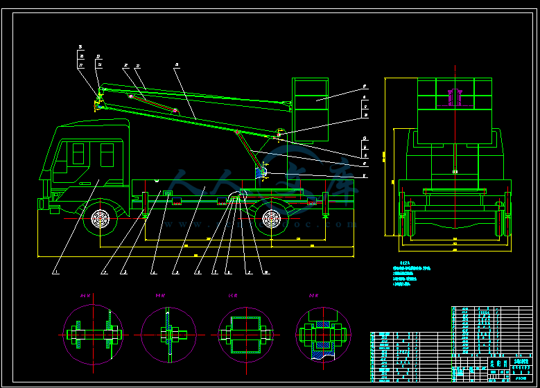
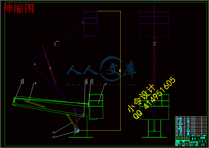
说明书-折叠臂式桥梁检测车的设计.doc

折叠臂式桥梁检测车的设计【6张CAD图纸+毕业论文】【答辩通过】

收藏

压缩包内文档预览:(预览前20页/共21页)
预览图 预览图 预览图 预览图 预览图 预览图 预览图 预览图 预览图 预览图 预览图 预览图 预览图 预览图 预览图 预览图 预览图 预览图 预览图 预览图
编号:437728    类型:共享资源    大小:2.60MB    格式:RAR    上传时间:2015-05-31 上传人:好资料QQ****51605 IP属地:江苏
45
积分
关 键 词:
折叠 桥梁 检测 设计
资源描述:

摘  要

随着公路交通的发展,我国的桥梁数量也迅猛增加。虽然在经济发展方面创造了良好的交通条件,但随之而来的检验维修问题将比较严重。由于桥梁的隐患问题而导致的交通事故往往是很严重的,因此,桥梁的安全越来越显得重要,从而产生了桥梁检测的问题,并由此衍生出一种新的检测工具--桥梁检测车。

我国未来几年的桥梁将保持着较快的速度发展,桥梁检测车在桥梁检测方面具有十分广阔的市场。

桥梁检测车是一种搭载检测设备和工作人员的改装汽车,因此安全显得特别重要。本文针对桥梁检测车的特点,以折叠臂式桥梁检测车为例子,结合液压控制系统,做如下研究:

1. 折叠臂式桥梁检测车的工作原理;

2. 对汽车设备的选型;

3. 支腿受力分析;

4. 液压控制系统。


关键词:桥梁检测车;折叠臂式;受力分析;液压控制


Abstract

With the development of highway traffic, the number of bridges in China is increasing rapidly. While in the aspect of economic development to create a good traffic conditions, but the subsequent inspection maintenance issues will be more serious. Due to the concerns of bridge caused by traffic accidents is often very serious, therefore, the safety of the bridge is more and more important, then produce the bridge detection problem, and thus derived a new detection tool - bridge inspection vehicle.

Chinese bridge in the next few years will remain relatively high speed development, bridge inspection vehicle has a very broad market in bridge inspection.

Bridge inspection vehicle is a kind of modified car carrying test equipment and staff, so is very important to safety. In this paper, according to the characteristics of the bridge inspection vehicle, with folding arm type bridge inspection vehicle car as an example, combined with the hydraulic control system, do the following research:

1. Folding arm bridge inspection vehicle automobile works;

2. Selection of automotive equipment;

3. Leg force analysis;

4. Hydraulic control system.


Keywords: bridge inspection vehicle; the folding arm type; leg force analysis; hydraulic control system


目  录

摘  要III

AbstractIV

目  录V

1 绪  论1

1.1 课题意义与背景1

1.1.1 课题意义1

1.1.2 课题背景1

1.2 桥梁检测车主要结构形式及国内外发展状况2

1.2.1 桥梁检测车主要结构形式2

1.2.2 国内外发展状况3

1.3 本文的主要研究内容5

2 桥梁检测车主要结构的设计6

2.1 折叠臂式桥梁检测车总设计方案6

2.2 总运动方案7

2.3 本章小结7

3 折叠臂式桥梁检测车的设备装置8

3.1 动力装置8

3.2 工作装置类型8

3.2.1 支腿机构8

3.2.2 举升机构9

3.2.3 回转机构9

3.2.4 作业平台的分析10

3.3 安全装置13

3.4 主题参数13

3.4.1 尺寸参数13

3.4.2 质量参数13

3.5 折叠臂式桥梁检测车地盘的选择14

3.6 本章小结14

4 举升机构与回转机构的设计15

4.1 举升机构设计15

4.1.1 举升机构运动范围15

4.1.2 动臂的结构设计和主要尺寸15

4.2 回转机构设计15

4.2.1 回转机构设计16

4.2.2 确定圆柱滚子的允许载荷16

4.3 本章小结17

5 支腿机构和液压系统设计计算18

5.1 支腿机构设计计算18

5.1.1 支腿跨距18

5.1.2 支撑脚接地面积20

5.2 液压系统设计20

5.2.1 液压系统原理分析20

5.2.2 油缸选型21

5.2.3 液压泵的选型与计算22

5.2.4 油箱容积与管路内径计算23

5.2.5 液压系统参数设计24

5.2.6 液压泵的选型24

5.3 本章小结24

6 折叠臂式桥梁检测车稳定性能分析25

6.1 支腿压力计算25

6.2 本章小结27

7 结    论28

致    谢29

参考文献30

附  录31


1 绪  论

1.1 课题意义与背景

1.1.1 课题意义

桥梁是国家的重要基础设施,桥梁是经济建设中的重要组成部分。桥梁的建设需要大量的资金投入,在经济社会中又有着重要作用,使得人们对桥梁的安全性、耐久性越来越重视。与此同时,桥梁长时间的使用,由于各种外界环境的影响,桥梁结构将不可避免地产生自然老化、损伤积累等各种各样的疲劳和损伤,这些损伤都将导致严重的交通事故,造成巨大的经济损失和人员伤亡。此外,早期设计与社会发展的不协调,很多桥梁承载能力已经达不到社会的需求、桥面宽度不能满足巨大的车流量,这就需要对原有桥梁的结构安全进行检测评估,鉴定它的实际承载能力,以确定加固改造方案;同时新建桥梁也须进行承载力检测,以检验其施,工质量,为竣工验收提供科学依据[1]。

对桥梁的结构损伤采取有效手段进行监测、预测和控制,不但可以发现桥梁当时的结构是否损坏或服务功能是否降低外,确保交通枢纽的安全和正常运行,并可获得下列的效益:(1)准确提供桥梁信息;(2)提供桥梁损坏程度信息;(3)对桥梁有完整的记录;(4)(5)及时维修;(6)对新建设的桥梁提供有效的信息[2]。

对桥梁裂缝进行长期的监测和寿命评估是十分重要的。由于大多数桥梁的结构裂缝主要产生在桥梁底部,检测起来很困难,与此同时桥梁结构形式日趋发展向大型化和新颖化,使这个问题更加难于解决。由此,桥梁检测己经成为一个巫待探索的研究领域。

1.1.2 课题背景

目前我国桥梁检测存在的主要问题表现在:

①设备不先进:

对于跨线桥等旱地上桥梁,多采用在桥梁的下方搭架,然后人员在架上工作的方式进行,对于跨河桥则采用船上搭架的方式进行,部分过高的桥梁或船只没法靠近的桥梁基本上找不到好办法来解决检测检查问题。

②耗资高:

搭设脚手架需要耗费更多的人力、物力、财力,而且从搭设到开始使用,最后再拆除也耗时较长,并且影响进度。交通影响大:

③安全小:

   工作人员站在支架上或者船上进行工作,容易造成事故。

④范围小:

   由于受到桥梁的具体环境和搭设支架的限制,现有的办法很难对桥梁的每一部分进行检测,只能选择有代表性的部分进行检查,这样也就使降低了我们对桥梁使用状况的掌握,如果设备陈旧、手段落后自然无法反映桥梁的全部现状,影响了对桥梁的质量评估。

   为了克服以上桥梁检测方式存在的问题,需要设计生产出一种可以为桥梁检测人员在检测过程中提供作业平台的专用设备。这就是通常大家所说的桥梁检测车,它实际上是一种用于桥梁检测维修作业的专用汽车,可以让作业人员随时移动位置,安全、快速、高效地进入作业位置。

   有专家认为,由于“十五”期间及至少未来10年内我国公路及桥梁建设仍将保持较快的发展速度,所以预计我国今后大型桥梁检测车等在内的道路养护检测机械车将具有十分广阔的市场。

专用的桥梁检测车通过液压伸臂机构,将检测装置(摄像机、超声波探测器等)或工作人员承载到桥梁底面任意位置的有效探测距离内,检测桥梁底部缺陷或进行维修。这种桥梁底部缺陷的检测方式,具有高效率,安全性好,较强适应性、低功率消耗等优点[3]。

因此,本文研究的目的和意义在于:

   1. 为研究和开发出新型智能化的检测装备,提供参考和基础。

2. 检测车析架结构小、工作臂长,可以穿过斜拉索,能准确、高效率地解决特大桥梁特别是斜拉桥底部缺陷的检测难题。

3.可将检测仪送到桥底的各个位置检测桥梁底部缺陷,取代人工探身桥底的检测方式,建立安全、可靠的无危险工作环境。

4.有效降低桥梁检测车的生产成本。

1.2 桥梁检测车主要结构形式及国内外发展状况

1.2.1 桥梁检测车主要结构形式

桥梁检测车是指装备有桥梁检测仪器和工作台,用于流动检测和(或)维修作业的专用汽车。它由汽车底盘和上装(上部工作装置)2部分组成。桥梁检测车最早出现在欧美,现在的装备技术已很先进,均采用电子液压控制,并配置有应急装置、稳定装置、遥控装置及发电设备。其上装结构型式有折叠臂式和桁架式2种。

(1)桁架式桥梁检测车

采用通道式工作平台,稳定性好,承载能力大,使用时检测人员能方便地从桥面进入平台或返回桥面,如配置升降机则可大大增加下桥深度。

(2)折叠臂式桥梁检测车

折叠臂式桥检车也叫吊篮式桥梁检测车,其结构小巧,受桥梁结构制约少,工作灵活,既可检测桥下也可升起检测桥梁上部结构,可有线、无线操作,灵活方便,有时候还可以做为高空作业车使用,价格相对析架式桥检车低[4]。

1.2.2 国内外发展状况

①国外状况:

桥梁检测车最早出现在欧美,美国HYDRA公司、Aspen Aerials(赛奔驰)公司,德国MOOG公司,意大利BAR工N公司等已有用于桥梁检测的检测车。现在的装备技术已很先进,均采用电子液压控制制,并配置有应急装置、稳定装置、遥控装置及发电设备。

意大利 BARIN(百灵):公司生产的 ABC 系列桁架式桥梁检测车最大水平工作范围6~23 m,最大下桥深度4~9.5m,最大承载质量300~800 kg,最大跨越宽度1.7~4.65m,最大跨越护栏高度2.0 ~5.4m∶AB系列折叠臂式桥梁检测车桥下最大水平距离6.5~22m,桥下最大垂直距离10~25.5m,桥上最大垂直距离8~20.5 m,吊篮最大载质量200~300kg[5]。

NIBL系列吊篮式桥梁检测车桥下最大水平距离12~16m,桥下最大垂直距离15~19. 5m,桥上最大垂直距离14~21m,吊篮最大载质量280 kg。

美国Aspen Aerials(赛奔驰):公司只生产折叠臂式桥梁检测车[6],主要产品型号有A~30,A~d0,UB~50,A~62,A~75,其桥下最大水平距离9.4~22. 8m,桥下最大垂直距离12.1~22m,桥上最大垂直距离9. 2~16.1m,吊篮最大载质量272~318 kg。所有Aspen Aerials桥梁检测车系列均可在无须装设液压支腿和配重的情况下进行平稳、安全、可靠地操作。

奥地利 PALFINGER (帕尔菲格)公司研发生产的 PA19000 型折叠臂式桥梁检测车,桥下吊篮最大水平伸长可达 16.2m,最大下桥深度 14m,最大承载质量 280 kg,吊篮向上最大举升高度 24.5m;美国 REACHALL 公司生产的 UB 系列折叠臂式桥梁检测车,桥下吊篮水平伸长可达到 13.2-18.6m,下桥深度可达15.8-21.3m,最大承载质量 272 kg,吊篮向上最大举升高度 10.7-14.4m。

②国内状况:

在我国,桥梁检测维修车尚处于研发的初级阶段。我国早在20世纪80年代末90年代初,由交通部公路规划设计院在北京起重机厂生产的QY~8型汽车起重机的基础上进行改造设计,最后以失败告终,后来国内又有几家单位研制也均以失败告终。最近几年,国内一批大型工程机械厂家开始从事桥梁检测车的研制,主要有徐工集团、湖南宝龙等,其产品和性能均能达到国外设备的标准。

   徐工集团:徐工集团成立于1989年,主要从事工程机械的研发和生产,1997年由徐工集团液压气动机械公司、西安公路交通大学和河南省公路局联合成功研制出XZJ5140JQJ10型折叠臂式桥梁检测车,结束了我国无桥梁检测车的历史[7]。

吊篮式(折叠臂式)桥梁检测车主要有QJ07, QJ12,QJ16、QJ16L,其桥下最水平距离8~16. 37 m,最大下桥深度10~20m,最大承载质量100~200 kg。

2006年1月,徐工集团成功研制出18m桁架式桥梁检测车,标志着徐工跻身于全球4大桥梁检测车生产领域,与意大利BARIN,德国MOOG、美国凯捷公司并驾齐驱,进入桥梁检测车系列化的快车道。目前该集团己经形成9~22m桁架式系列产品,最大水平工作范围9~21. 9m,最大下桥深度6~8.5m,最大承载质量600~800kg,最大跨越宽度2.1~2.5m,最大跨越护栏高度2.0~3.2m。

湖南恒润高利有限公司湖南恒润高利有限公司,有多年的高速公路建设与养护经验,是以提供满足客户需求的高品质道路养护机械为目标,集产品研发、制造、营销为一体的专业化工程机械企业。

2009年2月,该公司根据市场行情和发展需要,参照德国MOOG桥梁检测车,在其基础上合理改进,井在吸取国内外桥梁检测作业车经验的基础上研制推出16 in桁架式桥梁检测作业车。该公司目前主要有HHR5250JQJ16,HHR5250JQJ08车型,其最大水平工作范围8~16 m,最大下桥深度7. 0m,最大承载质量600~700 kg,最大跨越宽度2. 1~2. 2 m,最大跨越护栏高度2.2m。

1.3 本文的主要研究内容

1. 根据桥梁检测的要求,确定桥梁检测车的总体方案和臂架机构的方案。

2. 设计出检测车臂架结构。

3. 液压控制操作方案。

4. 折叠臂式桥梁检测车的稳定性。


内容简介:
无 锡 太 湖 学 院 毕业设计(论文)外文资料翻译院 (系): 信 机 系 专 业: 机械工程及自动化 班 级: 机 械 93 姓 名: 殷 晓 锋 学 号: 0923149 外文出处: 附 件: 1.原文;2.译文 2013年 5月编号无锡太湖学院毕业设计(论文)相关资料题目: 折叠臂式桥梁检测车的设计 信机 系 机械工程及自动化专业学 号: 0923110 学生姓名: 殷晓锋 指导教师: 黄敏 (职称:副教授 ) (职称: )2013年5月25日目 录一、毕业设计(论文)开题报告二、毕业设计(论文)外文资料翻译及原文三、学生“毕业论文(论文)计划、进度、检查及落实表”四、实习鉴定表无锡太湖学院毕业设计(论文)开题报告题目: 折叠臂式桥梁检测车的设计 信机 系 机械工程及自动化 专业学 号: 0923110 学生姓名: 殷晓锋 指导教师: 黄 敏(职称:副教授) (职称: )2012年11月25日 课题来源自拟题目科学依据(1)课题科学意义桥梁检测车是一种可以为桥梁检测人员在检测过程中提供作业平台,装备有桥梁检测仪器,用于流动检测和(或)维修作业的专用汽车。它可以随时移动位置,能安全、快速、高效地让检测人员进入作业位置进行流动检测或维修作业。工作时不影响交通,而且可以在不收回臂架的情况下慢速行驶。桥梁检测车技术含量很高,涉及到机械、液压、电子、雷达、通信等先进技术。具有效率高、安全性好、适应性强、功率消耗低等优点,适用于特大型公路桥、城市高架桥、铁路桥、公铁两用桥的预防性检查和维修作业,并为操作者在检测每一组成部分时提供安全保障,还可用于环境险恶不适合人工检测的场合。 这种车辆一般是在二类货车底盘基础上加装专用工作装置而成的。(2)折叠臂式桥梁监测车的研究状况及其发展前景:折叠臂式桥梁检测车一般具有以下特点; 采用机、电、液、讯一体化技术,控制系统采用电液比例及自动伺服调平技术,能精确控制每个细微动作; 一般采用一级伸缩、二级回转、二级变幅机构,形成二维空间、6个自由度的空间运动体系,工作臂可跨越一定宽度和高度的障碍物,以便顺利将工作斗或工作平台伸至桥下,安全、快捷地将工作人员和设备送到桥下幅度允许的任意位置; 工作斗中加装先进的过载保护系统,可实时监控作业平台负荷,超载报警并自动限制操作,确保检测作业的安全性,若采用工作平台,则需具有自动液压水平调节功能,确保工作平稳; 根据实际情况在底盘上加装支腿稳定器,并保证能使整车在桥下检修工作状态下行驶。桥梁检测作业车的发展适应了社会的需要,市场空间广阔,但由于技术含量较高,可靠性、安全性要求较高,而非一般企业所能生产。国内有条件的专用车生产厂应抓住有利时机和机遇,尽快提高我国桥梁检测车的技术水平,降低生产制造成本,提升市场竞争力。研究内容(1) 了解折叠臂式桥梁检测车的工作原理,国内外的研究发展现状;(2) 完成折叠臂式桥梁检测车的上体机的总体方案设计;(3) 完成零部件的选型计算、结构强度校核;(4) 熟练掌握有关计算机绘图软件,并绘制装配图和零件图纸,折合A0不少于3张;(5) 完成设计说明书的撰写,并翻译外文资料1篇。拟采取的研究方法、技术路线、实验方案及可行性分析研究方法:通过参阅借来的参考资料,并对折叠臂式桥梁检测车进行实体观察,认真研究上体机结构,了解折叠臂式桥梁检测车工作原理,与指导老师交流来完成对折叠臂式桥梁检测车结构的毕业设计。技术路线:提出任务分析对机器的需求确定任务要求,完成设计任务书。方案设计阶段对检测车功能进行分析提出可能的解决方案,组合几种可能的方案进行评价决策,选定最优方案该阶段目标为提出原理性的设计方案原理图或机构运动见简图。技术设计阶段明确构形要求结构化选择材料决定尺寸,评价再决策,确定结构形状及尺寸,零件设计、部件设计、上体设计,该阶段完成上体结构、草图及部件装配草图,并绘制出零件图部件图总装图最后完成技术文件的编制其中包括编制设计计算说明书、使用说明书、标准明细表、其他技术文件等。技术可行性:作为机械专业的学生所常用的必备软件,CAD、UG软件。研究计划及预期成果研究计划:2012年11月12日-2012年1月20日:按照任务书要求查阅论文相关参考资料,填写毕业设计开题报告书,并实训。2013年2月11日-2013年2月23日:找一篇相关外文期刊并翻译。构建框架,完成第一章绪论。2013年3月4日-2013年3月8日:完成总的结构方案设计。2013年3月11日-2013年4月20日:开始绘图,完成装配图以及部件图的绘制。2013年4月22日-5月3日:着手写说明书初稿,修改,完成初稿。2013年5月6日-5月10日:修改说明书并定稿,打印,整理资料准备答辩。特色或创新之处(1)主题明确,有针对性,稳定, 易操作, 通用性强。 (2)使用简易,功能完善。已具备的条件和尚需解决的问题(1)技术条件:整体构架基本明确,有电脑,有CAD作图软件。(2)尚未解决的问题:技术还不够成熟。指导教师意见 指导教师签名:年 月 日教研室(学科组、研究所)意见 教研室主任签名: 年 月 日系意见 主管领导签名: 年 月 日英文原文An innovative method for remote measurement of minimum vertical underclearance in routine bridge inspectionB. Riveiro a, D.V. Jauregui b, P. Arias c, J. Armesto c, R. Jiang da.Department of Materials Engineering, Applied Mechanics and Construction, School of Industrial Engineering, University of Vigo, C.P. 36208, Vigo, Spainb. Department of Civil Engineering, College of Engineering, New Mexico State University, Las Cruces, NM, USAc.Department of Natural Resources and Environmental Engineering, School of Mining Engineering, University of Vigo, C.P. 36310, Vigo, Spaind.Department of Engineering Technology and Surveying Engineering, College of Engineering, New Mexico State University, Las Cruces, NM, USAArticleinfoabstractArticle history:Accepted 18 April 2012Available online 17 May 2012This paper presents an innovative and low cost procedure for the complete and accurate measurement of minimum vertical underclearance in a safe environment for operators. This procedure draws on the principlesof terrestrial convergent photogrammetry which makes possible the reconstruction of the bridge components and surrounding features in 3D space. Using themeasured 3D coordinates, an algorithm was developed in the Matlab software to calculate the vertical underclearance. Furthermore, a procedure based on 3D curve fitting was developed to estimate the mathematical expression of the beam curve. The resulting methodology is suitable and advantageous for implementation in routine bridge inspection because it provides a more extensive and accurate measurement of vertical underclearance under much safer conditions. In addition, the estimate of the beam equation can be used not only for clearance measurement but also for periodic monitoring of the beam shape over time.Keywords:Bridge inspection ;Close range photogrammetry ;Vertical underclearance.1 IntroductionIt is true that extensive knowledge of the functional and conservation states of a structure is needed in order to properly schedule its maintenance and ultimately, ensure its preservation. Periodic monitoring of geometry usually plays a key role in the detection of structural anomalies, and in some cases such as stone arch bridges, can aid in preventing collapse due to problems with equilibrium and stability 1. In the case of modern bridges (mainly composed of concrete or steel), although the diagnosis of their condition state is assessed based primarily on the physical condition of the structural elements, the external shape and geometry also plays a very important role in the overall evaluation. The presence of deterioration, defects, and damages (e.g., impact damage caused by truck collisions, concrete spalls or delaminations, fatigue or shear cracks, section loss) and evidence of irregular movement are the most important parameters considered during a routine bridge inspection, and move advanced tools for their detection and quantification need to be investigated.Bridge inspection is a key factor in the maintenance and preservation of the civil infrastructure of a country. Many parameters have to be periodically evaluated in order to determine the physical condition of the structure 45. In the bridge management protocol of transportation agencies, there usually exists an initial phase focused on routine inspection, where, by means of quick and simple documentation, the first diagnosis of the current state of the structure is obtained 68. When some evidence of distress about the physical condition or stability of the structure is found in this initial step such as excessive beam sag or support settlement, a special inspection plan should be initiated to perform an in-depth evaluation of the bridge. Currently, there are several basic techniques available to measure irregular bridge movement such as plumb bobs, laser levels, theodolites, and total stations.Horizontal and vertical clearances are important geometric parameters that must be measured to a high level of accuracy during a routine bridge inspection. The acquisition of these dimensions is traditionally accomplished by means of basic contact tools such as tape measures and range poles that lack metric accuracy, and which also require the operators to perform the clearance measurements under dangerous traffic conditions. Fig. 1 illustrates the use of a range pole to measure the minimum vertical underclearance which is the distance from the roadway or railroad track beneath the bridge to the underside of the superstructure . As shown in the figure, measurements are usually taken at discrete points on the bottom surface of the beam to save time and also due to safety concerns. Furthermore, it is difficult to keep the range pole perfectly vertical to obtain an accurate measurement particularly for higher clearances. Consequently, it is possible that the minimum vertical underclearance is not measured accurately at the correct location. There are 116 items of bridge data used by the FHWA to monitor and manage the National Bridge Inventory (NBI) in the United States as given in the Structure Inventory and Appraisal (SI&P) sheet. The data are divided between inventory items that pertain to the permanent conditions of the bridge and appraisal items that pertain to the condition of the bridge component in comparison to current standards . In the SI&P sheet, geometric data are considered inventory items under which the minimum vertical underclearance is item 54. This particular item is coded with 5 digits; the first digit represents the reference feature (highway or railroad beneath structure) and the remaining four digits represent the minimum vertical underclearance (in feet and inches). Underclearance information is used by personnel involved with the permitting of oversize/overweight vehicles and is used in evaluating the sufficiency of a bridge to remain in service (i.e., sufficiency rating). Four separate factors are determined (using 19 of the 116 items reported in the SI&A sheet) to arrive at the sufficiency rating:(1) structural adequacy and safety; (2) serviceability and functional obsolescence; (3) essentiality for public use; and (4) special reductions. Horizontal and vertical underclearances and the deck condition affect the second factor while the superstructure and substructure conditions affect the first factor. The sufficiency rating ranges from 0 to 100% with the latter percentage representing an entirely sufficient bridge. Bridges qualify for replacement when the rating falls below 50% and rehabilitation when the rating falls below 80% . In spite of the simplicity and rapidity in using traditional instruments, the quality of metric results is poor. Surveying techniques offer better quality results in terms of accuracy, but these methods have important limitations for regular use in relation to handling of equipment and the amount of data collected. Terrestrial photogrammetry and laser scanning are two geomatic techniques which have significantly evolved, being more and more used in diverse fields including architecture 9,10; civil engineering 1114; industry15,16;and archaeology 17,18. Many investigations show the potential of these new technologies in the field of bridge engineering 19. From the captured precise 3D geometry of bridges, for example, an improved assessment of the structure can be made 20. Laser scanning is gaining popularity due to its simplicity in usage and speed of acquisition 21. A few studies of damage detection in concrete bridges using terrestrial laser scanner data can be found in 2224. Similar to traditional surveying equipment, laser scanning presents important limitations for routine inspection work including cost of equipment, necessity for trained operators, and amount of data stored during the bridge survey. Consequently, low cost technologies capable of collecting meaningful and accurate metric data without the need for overly complicated equipment operation and extensive data processing are needed. Close range photogrammetry has several strengths that make it a suitable method for measuring bridge features during a routine inspection such as it utilizes low cost equipment, it is relatively easy to use, and it provides high metric precision. An extensive review of the application of this technique in bridge engineering can be found in 19. Gonzalez-Aguilera and Gmez-Lahoz 25 present a novel photogrammetric system based on a single image for obtaining the overall geometry of bridges by means of dimensional analysis. Other studies related to bridge monitoring based on photogrammetric methods included those performed by Chang and Ji 26 and Hang et al. 27. Before new technologies are included in the protocols for metric documentation, they must first be validated. In this context, methodologies of surveying need to be adapted to overcome the existing difficulties in routine bridge inspection. This paper presents an innovative and low cost procedure for the complete and accurate measurement of minimum vertical underclearance in a safe environment for operators. This procedure draws on the principles of terrestrial convergent photogrammetry which makes possible the reconstruction of the bridge components and surrounding features in 3D space.Using the measured 3D coordinates, an algorithm was developed in the Matlab software to calculate the vertical underclearance. Furthermore, a procedure based on 3D curve fitting was developed to estimate the mathematical expression of the beam curve. The resulting methodology is suitable and advantageous for implementation inroutine bridge inspection because it provides a more extensive and accurate measurement of vertical underclearance under much safer conditions. In addition, the estimate of the beam equation can be used not only for clearance measurement but also for periodic monitoringof the beam shape over time.2 Theoretical backgrounds2.1 Photogrammetric processClose range photogrammetry is a non-destructive geomatic technique which allows the 3D shape of objects to be reconstructed from photographic images. The conversion from 2D information of images to 3D models is achieved by means of the photogrammetric process. Two main steps contribute to this process: inner orientation and external orientation. The inner orientation reconstructs the internal geometry of the imaging system, which defines the perspective system, by means of the camera calibration process. The metric parameters obtained from the camera calibration include the 3D position of the perspective centre in the image space (focal length and principal point on the sensor), sensor dimensions, and lens distortions. The lens distortions are sources of errors during the image recording and must be compensated for to obtain the most accurate reconstruction of the 3D model. The symmetric radial distortion significantly influences the photogrammetric reconstruction as shown in 28,29. There are two common formulations for radial distortion: balanced and unbalanced models. Although these models can be mathematically equivalent, the balanced model results in smaller apparent distortions so is commonly used by camera and lens manufacturers 3032. The external orientation locates the relative position of each camera used in the 3D reconstruction process at the time images were taken. Hence, if the position of one camera is known, the relative external orientation is done using the positions (X, Y, Z) and orientations (, , ) of the other cameras. For a given point in an object space, the coplanarity condition requires that the points position in two overlapped images and the cameras perspective centre are situated in the same plane. As shown by Krauss in 33, the relative orientation of images is achieved when the image coordinates of Fig. 1.Fig. 1. Measurement of minimum vertical underclearance during a routine bridge inspectionMeasurement of minimum vertical underclearance during a routine bridge .Inspection five points are known. The external orientation is completed when the model is scaled and placed in the absolute coordinate system.When the relative camera position is solved, the camera perspective centre Oi, a point in the image (xi, yi), and the position of this point over the surface of the object (X, Y, Z) are located in the same straight linebased on the collinearity equation. It is then possible to obtain the 3D position of a point on the object surface from measurements in the image. The mathematical principles of this process are further explained in 34 and 35. 2.2 3D fitting algorithmThe shape of object surfaces can be usually modelled by means of parametric surfaces. When a set of data points defining the object surface is available, a function of two independent variables (x and y) can be determined to best fit a parametric surface to the data. For 3D curve fitting, a dependent variable f can be modelled from two independent variables x and y, where data are a set of n3D points (xi, yi, fi), for i=1: n, nN. In this case, object points with three spatial coordinates (xi, yi, zi) are obtained from the photogrammetric process. Xi and Yi components of space points are initially aligned according to transversal and longitudinal bridges directions, respectively. Zi corresponds to the vertical component (clearance direction).This 3D information provides the two independent variables (x and y) as well as a third component zi for the minimization of the following expression.3 Methodology3.1 InstrumentationTo be feasible, an important aspect to consider in the effort to enhance routine bridge inspection work is maintaining the simplicity of equipments used for basic inspection tasks while providing better documentation. For this reason, the measurement procedure developed in this study was based on simple field setups and the usage of digital cameras which do not require advanced knowledge of digital image recording by operators. A digital, semi-metric camera (Canon EOS 10D) equipped with a CCD sensor, RGM matrix resolution of 6.29 million pixels and a Canon EF 20 mm f/2,8 lens was used for image acquisition. External information with real dimensions of a reference body is required in order to get the 3D model scaled. In this sense, duringthe execution of this project a reference distance was obtained by means of measuring coordinates of two control points. To validate the photogrammetric results, separate measurements using topographic equipment were made. A total station (Leica model TCR 1203+) was used to measure a set of points defining the lower profile of the beam and control points. The technical features of the instrument include long-range coverage (up to 400 m); 2 mm+2 ppm accuracy; 10 cc angular accuracy (1 cc typical average measurement in angles deviation);and 6/2 mm sensitivity of levels.3.2 Camera calibrationThe cameras are calibrated under fixed imaging parameters in the laboratory prior to the field work. Consequently, operators only have to acquire a few photographs during the actual bridge survey (field calibration requires significantly more photographs). The camera calibration process is performed in the “Calibration module” of the Photomodeler Pro software using a scaled planar grid of points which is captured by means of several images from different points of view. The calibration images are marked and imported into the photogrammetric platform where the geometric parameters of the camera are almost automatically obtained. The parameters representing the inner orientation of the camera used in this study are presented in Table 1, as well as the components of the mathematical polynomials that model the radial (K1 and K2) and tangential (P1 and P2) lens distortions. Based on the sensor dimensions given in the table, the pixel size amounts to 7.3 m, which together with the principal distance of the image system, determines the maximum perceived detail of objects captured in a digital image. The spatial resolution of an image over the object surface can be calculated as the pixel size projection or GSD (ground sample distance) by means of the following expression(2),where, A is the mean distance to the object, f is the principal distance of the calibrated camera and sx is the pixel size calculated from the CCD size of the camera sensor and image resolution. Based on the computed values of pixel size and principal distance, for instance, the pixel size projection expected is 11 mm if an operator is working with averaged object distances of 30 m. Consequently, the minimum error of measurement from images will exceed this value. 3.3 Data acquisitionOnce the cameras are calibrated, they can be directly used in the field. For the measurement of vertical clearance, as well as other geometric features, the methodology for data acquisition consists of the following steps: Selection of camera parameters according to the internal configuration determined from camera calibration. Definition of camera stations. According to the principles of convergent photogrammetry, cameras should maintain convergence angles of 90 degrees. This angle is defined by the maximum angle between the main directions of the cameras from the vertex to the same point on the object surface. Fig. 2 illustrates the recommended geometry of the camera network. Reference system has to be established. For this purpose, a reference distance has to be known in the object space, preferably measured around the imaginary plane where vertical clearance is goingto be measured. Adequate framing. It is important to ensure that the structure entirely fits into the image and that the structure takes up the most possible space in the photo area. This image configuration optimizes the spatial resolution over the bridge surface, since it corresponds to the minimum operative distance between camera and object, and, consequently, the minimum GSD value achievable. Furthermore,overlap between convergent images should always be higher than 60% of the photo area, otherwise external orientation of the images cannot be realized. Image acquisition. Images must be captured ensuring adequate exposure levels and thus, it is important to use a tripod when natural light is not sufficient and the shutter speed required is longer than 1/30 s. Lighting conditions are very important during image acquisition because underexposed images or images with excess brightness and reflections may lead to mistakes during image restitution, and consequently, a reduction of the measurement accuracy. Data storage. Most digital cameras directly store the data into portable memory devices which subsequently may be downloaded to a PC or workstation. An advantage of digital cameras is the capability to control the image acquisition process via a camera control software installed on a PDA or tablet PC.Fig. 2. Recommended geometry of camera network for image acquisition during routine bridge inspection.Table 1 Calibration parameters of Canon EOS 10D+20 mm lens, and standard deviation of Values.3.4 Data processingFollowing the field work, the images previously stored in the cameras digital media are downloaded to the workstation in the laboratory. The photogrammetric process starts when the parameters of camera calibration are imported and the perspective geometry of the rays from the image points is modelled. Next, the location and orientation of images in the reference system may be found. It is first necessary to provide the information needed for the bundle adjustment. As mentioned previously, six common points (five plus a proof point) between convergent images produces a determinate system of equations, the solution of which gives the relative external orientations of the images. The model is scaled in real space via the reference distance used during image acquisition. This reference distance was accurately measured by surveying methods, with the same accuracy of the truth data of the experiment. Optionally, the operator can define the orientation of the project coordinate system, for example, using the main vertical plane of the structure as the YZ plane. Extraction of the point clouds is then achieved during the process of restitution (reconstruction of 3D point positions) on the pavement and bottom contour of the beam. Once the 3D position of the object points is calculated they are exported to text files. These files are then imported into the algorithm developed in the Matlab software where the calculation of the minimum vertical underclearance is performed.3.5 Minimum vertical clearance algorithmTo estimate the minimum vertical underclearance, an algorithm based in 3D curve fitting was developed using the Matlab software. The input data is composed of two files that contain: the coordinates of the 3D points measured on the pavement, and those measured on the bottom beam contour, respectively. The first point cloud is fitted to a plane, whose normal vector defines the vertical line of the system. Once the verticality is defined, the points of the pavement are readjusted to a 3D surface that best fits the road shape on the basis of least squared fitting. On the other hand, the points of the beam contour are fitted to a fourth degree polynomial curve to estimate the beam camber. The vector in longitudinal direction of the 3D fitted curve, and the vertical vector defined by the pavement surface result in a plane from which the minimum vertical underclearance is measured. This inspection value is calculated as the difference between the beam curve and the vertical projection of the curve over the pavement surface. It is important to note that the vertical clearance is measured along the beam length and consequently, the minimum underclearance can be calculated as well as its relative longitudinal position on the beam. This position is also located in the photograph of the bridge structure so it is possible to monitor any changes in the vertical clearance between consecutive inspections. Additionally, this algorithm calculates the equation of the beam camber so it is possible to monitor the beam deflection and consequently, this parameter can be used to evaluate potential problems such as excessive prestress losses.4 ResultsThe methodology developed in this article was applied to a prestressed concrete highway bridge, whose beams are the structural elements which define the minimum vertical underclearance of the bridge. The bridge evaluated is named the Dr. C. Quentin FordBridge (hereafter referred to as the Ford Bridge) and carries the I-25 interstate highway in Las Cruces, New Mexico, USA. The validation of the methodology was done through comparison of the measurements obtained with the photogrammetry and topographic equipment described earlier and shown in Fig. 3. The total station provided an independent check of the photogrammetric measurements of vertical clearance and beam camber.4.1 Photogrammetric resultsThree different sets of points were obtained from the photogrammetric analysis: points restituted on the pavement surface; points defining the lower beam profile; and a set of control points located throughout the bridge area. Control points were measured to quantify the accuracy of the photogrammetric measurement system. shows the precision of the restituted points calculated as the standard deviation of each point after the bundle adjustment. As shown by the table values, the level of precision of the three data sets (beam, pavement and control points) is similar.4.2 Point-to-point measurementThe control points were measured with the total station with the aim of checking the accuracy of the 3D restitution of single points. As shown in Table 3, the precision of photogrammetric points is significantly lower than the point precision attained by the total station. Thus, the topographic measurements were taken as the true values of the control points by which the accuracy of the photogrammetricresults were evaluated. Since both measurements belong to different coordinate systems, a 3D conformal transformation 36 was applied to the photogrammetric measurements to correlate with the coordinate system defined by the total station. The residuals of the transformation represent the accuracy of each control point and were calculated as the vector distance between the real point position and the position of the transformed photogrammetric points. Table 3 presents the photogrammetric and topographic precisions and the transformation residuals for each control point. As can be seen, precision values in X component (direction parallel to cameras principal length) are significantly lower than those in the other directions, because in that direction the depth of spatial data is very low compared with the other directions.4.3 3D fitting algorithmFor the vertical underclearance measurement, the 3D coordinates of the beam and pavement points were exported in ascii format. These files were subsequently imported into the 3D fitting algorithm developed in the Matlab software and the automatic clearance measurement was carried out separately using the photogrammetric and topographic data. Fig. 4 shows the vertical underclearance values along the beam principal direction obtained from both sources of data as well as the accuracy for each point (computed as the vertical difference vector between measured and fitted points). The average precision in the polynomial fitting was 0.026 m for the photogrammetric data and 0.002 m for the total station data. As expected, the error of the adjusted point cloud is better than the average precision of single points for both measurement systems 37.4.4 Minimum vertical clearance and defection curve parameterizationAs shown in Fig. 5, the minimum vertical underclearance was measured at the left end of the beam with a real (topographic) value of 5.247 m and an estimated photogrammetric value of 5.222 m. According to the proposed methodology, the user can measure the vertical underclearance at any position along the beam so it will be possible to monitor the same position during successive routine inspections of the structure. In addition, the beam camber can be monitored by comparison of the deflection curves, whose mathematical representation is also provided by the algorithm developed.5 ConclusionsThis article presents a novel methodology for the measurement of minimum vertical underclearance during routine bridge inspections. The methodology is based on the principles of 3D measurement by terrestrial photogrammetry which provides a high level of metric precision. To automate the clearance measurement process, an algorithm based on 3D curve fitting was developed in the Matlab software whose data entry are the 3D information obtained from the photogrammetric analysis. The proposed methodology was validated by means of comparison with topographic data. Averaged vertical clearance difference, between the photogrammetric results and the real data, was 0.008 m; and the average precision of the adjustment achieved were 0.017 m and 0.0013 mfor photogrammetric and topographic data respectively. Both systems of measurement found the minimum value of vertical underclearance at the same location along the beam, which equaled 5.2220.025 mbased on the photogrammetric method. These results support the implementation of photogrammetry in the protocols of routine bridge inspections due to its high level of accuracy. In summary, this investigation showed that photogrammetry is suitable for use in routine bridge inspections because it provides an accurate measurement technique for minimum vertical underclearance. One of the most important advantages of this procedure is that it provides a safe environment for operators, particularly in high capacity roads, since operators do not need access to the roadway or rail to perform the measurement. In addition, the estimate of the mathematical expression of the beam curve can be used not only for clearance measurement but also for periodic monitoring of the beam camber over time.It is important to note that the specific equipment used in this study only permitted identifying objects whose size was bigger than 0.011 m (spatial resolution of camera system due to experiment configuration). For the same average range of measurement and the same focal length, a camera with a pixel size smaller than 4 m would provide us with a spatial resolution of 6 mm. Additionally, if a great angular lens of, for example, 50 mmis mounted on the camera instead of a 20 mm focal length one the achievable spatial resolution could be approximately 2.5 mm. Hence, future research should be focused towards the validation of different camera systems to maximize the level of accuracy of the proposed methodology. Acknowledgments The financial support of the Ministry of Science and Education (Spain) for Scientific Research under Grant No. BIA2009-08012, the Spanish Centre for Technological and Industrial Development (Grant No., IDI-20101770) and Human Resources Program of the Ministry of Science and Education (AP2006-04663) is gratefully acknowledged.References1 G.A. Drosopoulos, G.E. Stavroulakis, C.V. Massalas, Influence of the geometryand the abutments movement on the collapse of stone arch bridges, Constructionand Building Materials 22 (3) (2008) 200210, /10.1016/j.conbuildmat.2006.09.001.2 FHWA, Bridge Inspectors Reference Manual Rep. No. FHWA NHI 03001, U.S. Department of Transportation, Washington, D.C., 200.3 G.C. Beolchini, V. Gattulli, R. Ghanem, Data fusion in bridge health monitoring for management, Proceedings of the First International Conference on Bridge Maintenance,Safety and Management, IABMAS 2002, Barcelona, 1417,July, 2002,2002.4 G.C. Beolchini, V. Gattulli, R. Ghanem, Data fusion in bridge health monitoring for management, Proceedings of the First International Conference on Bridge Maintenance,Safety and Management, IABMAS 2002, Barcelona, 1417,July, 2002,2002.5 L. Bevc, B. Mahut, K. Grefstad, Review of Current Practice for Assessment of Structural Condition and Classification of Defects, Project funded by the European Commission under the transport rtd. program of the 4th Framework Program,2001 61 pp.6 V. Gatulli, L. Chiaramonte, Condition assessment by visual inspection for a bridge management system, Computer-Aided Civil and Infrastructure Engineering 20 (2005) 95107.7 A. Estes, M. Frangopol, Updating bridge reliability based on bridge management systems visual inspection results, Journal of Bridge Engineering 8 (2003) 374382.8 P. Arias, J.C. Caamano, H. Lorenzo, J. Armesto, 3D modeling and section properties of ancient irregular timber structures by means of digital photogrammetry, Computer- Aided Civil and Infrastructure Engineering 22 (8) (2007) 597611.9 C. Ordez, J. Martnez, P. Arias, J. Armesto, Measuring building faades with a low-cost close-range photogrammetry system, Automation in Construction 19 (2010) 742749.10 B. Riveiro, J.C. Caamao, P. Arias, E. Sanz, Photogrammetric 3D modelling, FEM and mechanical analysis of masonry arches behaviour: an approach based on a discontinuous model of voussoirs, Automation in Construction 20 (2011) 380388.11 R. Jiang, D.V. Jauregui, Development of a digital close-range photogrammetric bridge deflection measurement system, Measurement 43 (10) (2010) 14311438.12 D. Jauregui, Y. Tian, R. Jiang, Photogrammetry applications in routine bridge inspection and historic bridge documentation, Transportation Research Record 1958 .(2006) 2432.13 M. Solla, H. Lorenzo, B. Riveiro, F.I. Rial, non-destructive methodologies in the assessment of the masonry arch bridge of Traba, Spain, Engineering Failure Analysis 18 (2011) 828835.14 T. Luhmann, Close range photogrammetry for industrial applications, ISPRS Journal of Photogrammetry and Remote Sensing (2010), /10.1016/ j.isprsjprs.2010.06.003.15 J. Porteiro, B. Riveiro, E. Granada, J. Armesto, P. Egua, J. Collazo, Refrigerated web camera for photogrammetric video measurement inside biomass boilers and combustion analysis, Sensors 11 (2011) 12461260.16 Y. Alshawabkeh, N. Haala, D. Fritsch, A new true ortho-photo methodology for complex archaeological application, Archaeometry 52 (3) (2010) 517530.17 R. Jiang, D.V. Juregui, K.R. White, Close-range photogrammetry applications in bridge measurement: literature review, Measurement 41 (8) (2008) 823834.18 I. Lubowiecka, J. Armesto, P. Arias, H. Lorenzo, Historic bridge modelling using laser scanning, ground penetrating radar and finite element methods in the context of structural dynamics, Engineering Structures 11 (2009) (2009) 26672676.19 R.C. Lindenbergh, Engineering applications, in: G. Vosselman, H.-G. Maas (Eds.),Airborne and Terrestrial Laser Scanning, Whittles Publishing, Dunbeath, Scotland,UK, 2010, pp. 237242.20 G. Teza, A. Galgaro, F. Moro, Contactless recognition of concrete surface damage from laser scanning and curvature computation, NDT&E International 42 (4) (2009) 240249.21 R. Pucinotti, M. Tripodo, The Fiumarella bridge: concrete characterization and deterioration assessment by nondestructive testing, International Journal of Microstructure and Materials Properties 4 (1) (2009) 128139.22 D. Gonzlez-Aguilera, J. Gmez-Lahoz, Dimensional analysis of bridges from a single image, Journal of Computing in Civil Engineering 23 (6) (2009) 319329.23 C.C. Chang, Y.F. Ji, Flexible videogrammetric technique for three-dimensional structural vibration measurement, Journal of Engineering Mechanics 133 (6) (2007) 656664.24 J.G. Han, K.H. Chang, G.C. Jang, K.K. Hong, S.D. Cho, Y.S. Kim, J.M. Kim, Y.E. Shin, Development of a visual monitoring system for deformation measuring of welded members and its application, Materials Science Forum 580582 (2008) 557560.25 J.G. Fryer, Camera calibration, Close Range Photogrammetry and Machine Vision,371, Whittle Publishing, Bristol, 1996, pp. 156179.26 K. Krauss, Photogrammetry Fundamentals and Standard Processes, vol. 1, Ferd. DmmlersVerlag, Bomm, 1993 397 pp.27 D.C. Brown, Close range camera calibration, Photogrammetric Engineering 37 (8)(1973) 855866.28F. Remondino, C. Fraser, Digital camera calibration methods: considerations and comparisons,ISPRS Commision V Symposium, Image Engineering and Vision Metrology, 5, 2006, pp. 266272.29K. Krauss, Photogrammetry. Geometry from images and Laser Scans, de Gruyter,Berlin,Germany, 2007.90T. Luhmann, T. Luhmann, S. Robson, K. Stephen, I. Harley, Close Range Photogrammetry:Principles, Methods and Applications, Whittles Publishing, Scotland,UK, 2006.31P. Arias, J. Herrez, H. Lorenzo, C. Ordez, Control of structural problems in cultural heritage monuments using close-range photogrammetry and computer methods, Computers and Structures 83 (2122) (2005) 17541766.32 M.J. Smith, T. Moore, Back to basics (8). Plane transformations, Survey Review 34(266) (1997) 237244.33S.J. Gordon, D.D. Lichti, Modeling terrestrial laser scanner data for precise structural deformation measurement, Journal of Surveying Engineering 133 (2007)7280.中文译文一种对于常规桥远程测量最小垂直方向净空的创新检查方法B. Riveiro a, D.V. Jauregui b, P. Arias c, J. Armesto c, R. Jiang da.Department of Materials Engineering, Applied Mechanics and Construction, School of Industrial Engineering, University of Vigo, C.P. 36208, Vigo, Spainb. Department of Civil Engineering, College of Engineering, New Mexico State University, Las Cruces, NM, USAc.Department of Natural Resources and Environmental Engineering, School of Mining Engineering, University of Vigo, C.P. 36310, Vigo, Spaind.Department of Engineering Technology and Surveying Engineering, College of Engineering, New Mexico State University, Las Cruces, NM, USA摘要文章历史接受2012年4月18日2012年5月17日在线本文提出了一种创新的、低成本的过程的完整和精确测量的最小垂直桥下净空。本程序利用我们的陆地收敛摄影测量使可能的重建这座桥组件和周围的特性在3d空间。使用测量三维坐标,一个算法在Matlab软件计算垂直方向桥下净空。此外,一个程序基于3d曲线拟合估算了数学表达式的梁曲线。生成的方法是合适的和便于实现在常规桥梁检查,因为它提供了一个更广泛和精确测量的桥下净空环境。此外,估计的波束方程不仅仅可以用来间隙测量也定期监测梁形状随时间。关键词:桥检查;近距离摄影测量;垂直富裕水深1 介绍的确,广博的知识和保护的功能对一个结构是非常必要的,以适当安排它的维护以确保其保存。定期监测在检验结构的稳定性通常扮演着关键的角色,并在某些情况下,如石拱桥,可以帮助防止崩溃,因为问题与平衡和稳定是非常重要的。对于现代桥梁(主要由混凝土或钢),尽管对于他们的病情的诊断状态进行了评估,主要基于物理条件的结构元素,外部的形状和几何也扮演一个重要的总体评价角色。恶化的存在、缺陷、或损失(如:由于卡车碰撞造成的损害,混凝土的破碎或分层、疲劳或剪切裂缝,部分损失)和因为不规则运动是最重要的参数,被认为是在每次例行桥检验,并用先进的工具为他们的检测和量化需要做进一步调查。桥检验是一个关键因素,维护和保存民用基础设施是一个国家发展的重要前提。许多参数要定期评估,以确定物理条件的结构。在桥的管理协议运输机构,通常存在一个初始阶段集中在常规检查,通过快速和简单的文档,第一个诊断的当前状态的结构获得一些证据表明遇险的物质条件或稳定的结构是发现在这个初始步骤比如过度梁凹陷或支持结算、特殊检查计划应该开始执行一个深入的评估桥。目前,有几种基本方法可用来衡量不规则桥梁运动如垂直上下摆动,激光水平,经纬仪和总站。水平和垂直的间隙几何参数是很重要的。这必须被测量,以高水平的精度在一次常规桥检验。收获这些维度是传统上完成通过基本的联系工具如卷尺和范围,缺乏精度指标,这也要求操作员执行在危险的间隙测量交通状况。图1演示了使用一个标杆来衡量最低桥下净空的距离巷道或铁轨桥下面的底部上层建筑。如图,测量通常采取离散点在底部表面的光束来节约时间,也出于安全方面的考虑。此外,很难保持标杆完全垂直获得一个准确的测量特别是对于更高的许可。因此,它可能是这最小的桥下净空不精确的测量在正确的位置。有116项桥所使用的数据供监控和管理国家桥库存(NBI)在美国给出在结构库存和评估(SI&P)表。这个数据分为库存项属于永久性的桥的条件和评估项目有关条件的桥接组件相比,当前的标准。在SI&P表、几何数据被视为库存根据该项目最低桥下净空是项54。这个特定的项目是编码与5位数,第一个数字表示参考特性(高速公路或铁路在结构)和剩余的4个数字代表了最低桥下净空(单位是英尺和英寸)。桥下净空信息是用人员参与这个允许的超大、超重的车辆和用于评估一座桥的充分性留在服务(即充分性评级)。四个因素决定(使用1911项目报告的SI&A表)到达充足等级:(1)结构的充分性和安全;(2)可服务性和功能过时性;(3)他对公共使用的可靠性;(4)经济因素。水平和垂直下部间隙和甲板条件影响第二个因素而上层建筑和基础条件影响的首要因素。充足的评级范围从0到100%,后者百分比表示一个完全足够桥。桥梁有资格申请更换当信用评级下调低于50%和康复当评级低于80%。尽管简单和迅速,在使用传统量具度量结果的质量很差。测量技术的提供更好的质量结果在计算精度,但这些方法有重要的限制日常使用与处理的设备和收集的数据的数量。地面摄影测量和激光扫描是两个演示技术且具有显著的发展,被越来越多的用于各种领域包括架构、土木工程行业和考古学。许多调查显示了潜在的这些新技术在桥梁工程的领域。从捕获的精确3 d几何的桥梁,例如:一种改进的评估的结构可以使激光扫描是越来越受欢迎,因为它很简单的用法和收获数据的速度。一些研究混凝土的损伤检测桥梁,使用地面激光扫描数据中可以找到类似的传统测量设备,激光扫描提出了重要的限制日常检验工作包括成本的设备,需要训练有素的运营商和一定数量的数据存储在桥的调查方面。因此,低成本技术能够收集有意义的和准确的度量数据,而不需要过于复杂设备操作和广泛的数据处理。近距离摄影测量有几个优势,使它成为一个适当的方法来测量电桥特性在一次例行检查,比如它利用低成本的设备,它是相对容易的使用,并且它提供了高公制精密。一个研究小组在审查该技术的应用在桥梁工程时发现这是可行的。冈萨雷斯阿奎莱拉提出一种摄影测量系统基于单个图像获取整体几何的桥梁通过量纲分析。有些新技术是包含在协议的度量文档,他们必须首先验证。在这种背景下,方法测绘需要适应克服在桥梁检测现有的困难。本文提出了一种创新和低成本的过程的完整和准确的测量最低垂直富裕水深在一个相对安全的环境。这个程序利用陆地的原则收敛摄影测量,这让可能的重建桥的组件和周围的特性在3d空间。使用3d坐标测量,研制了一种算法在矩阵实验室软件计算垂直富裕水深。此外,一个程序基于3d曲线拟合是发达的估计数学表达式的梁曲线。结果方法论是合适的,便于实现常规桥检查,因为它提供了在垂直桥下净空方面一个更广泛的和更精确的测量的安全条件。此外,估计的梁方程可以不仅用于间隙测量还可以定期监测随着时间的桥梁的形状。2 理论背景近距离摄影测量是一种无损演示技术。它允许3d物体的形状是从摄影图片重建。从2d转换的信息图片,3d模型是通过摄影测量的方式和外在取向过程。两个主要步骤有助于这个过程:内在取向和外在取向。内在取向建构是内部几何成像系统,它定义了视角系统,通过相机的标定过程。度量参数获得从摄像机标定包括3d位置的角度来看中心
温馨提示:
1: 本站所有资源如无特殊说明,都需要本地电脑安装OFFICE2007和PDF阅读器。图纸软件为CAD,CAXA,PROE,UG,SolidWorks等.压缩文件请下载最新的WinRAR软件解压。
2: 本站的文档不包含任何第三方提供的附件图纸等,如果需要附件,请联系上传者。文件的所有权益归上传用户所有。
3.本站RAR压缩包中若带图纸,网页内容里面会有图纸预览,若没有图纸预览就没有图纸。
4. 未经权益所有人同意不得将文件中的内容挪作商业或盈利用途。
5. 人人文库网仅提供信息存储空间,仅对用户上传内容的表现方式做保护处理,对用户上传分享的文档内容本身不做任何修改或编辑,并不能对任何下载内容负责。
6. 下载文件中如有侵权或不适当内容,请与我们联系,我们立即纠正。
7. 本站不保证下载资源的准确性、安全性和完整性, 同时也不承担用户因使用这些下载资源对自己和他人造成任何形式的伤害或损失。
提示  人人文库网所有资源均是用户自行上传分享,仅供网友学习交流,未经上传用户书面授权,请勿作他用。
关于本文
本文标题:折叠臂式桥梁检测车的设计【6张CAD图纸+毕业论文】【答辩通过】
链接地址:https://www.renrendoc.com/p-437728.html

官方联系方式

2:不支持迅雷下载,请使用浏览器下载   
3:不支持QQ浏览器下载,请用其他浏览器   
4:下载后的文档和图纸-无水印   
5:文档经过压缩,下载后原文更清晰   
关于我们 - 网站声明 - 网站地图 - 资源地图 - 友情链接 - 网站客服 - 联系我们

网站客服QQ:2881952447     

copyright@ 2020-2025  renrendoc.com 人人文库版权所有   联系电话:400-852-1180

备案号:蜀ICP备2022000484号-2       经营许可证: 川B2-20220663       公网安备川公网安备: 51019002004831号

本站为文档C2C交易模式,即用户上传的文档直接被用户下载,本站只是中间服务平台,本站所有文档下载所得的收益归上传人(含作者)所有。人人文库网仅提供信息存储空间,仅对用户上传内容的表现方式做保护处理,对上载内容本身不做任何修改或编辑。若文档所含内容侵犯了您的版权或隐私,请立即通知人人文库网,我们立即给予删除!